Sonniger GUARD Installation guide

Operation and Maintenance Documentation GUARD v202301
Operation and Maintenance Documentation GUARD
SONNIGER S.A.
ul. Śląska 35/37, 81-310 Gdynia, Poland, infolinia 801 055 155, tel. + 48 58 785 34 80, www.sonniger.com
Sąd Rejonowy Gdańsk-Północ, VIII Wydział Gospodarczy Krajowego Rejestru Sądowego, KRS 0000966611, NIP 5862273514,
Regon 22154369 kapitał zakładowy: 1.655.000 PLN
Operation and Maintenance Documentation GUARD v202301
1. PURPOSE OF THE DEVICE
The air curtain is intended to be used in regions with a moderate and cold climate, in spaces where the temperature ranges
from -10 to +40°C, in conditions free from external factors such as pollens and hydrometeor (horizontal precipitation).
In winter, air curtains protect against heat loss in rooms by directing an airstream across the entrance and preventing cold air
from entering the heated space. In summer, the curtains may be used as cooling devices preventing the entry of hot air and
pollutants from outside.
The GUARD air curtains are designed to protect against heat losses in buildings of medium and high capacity and with a
required mounting height of 4 m such as:
supermarkets, large retail spaces,
car showrooms and service stations,
sports and show halls,
exhibition surfaces
2. BASIC TECHNICAL PARAMETERS
TECHNICAL PARAMETERS
Curtain with water heater Curtain with electric heater Curtain without heater
GUARD 100W
GUARD 150W
GUARD 200W
GUARD 100E
GUARD 150E
GUARD 200E
GUARD 100C
GUARD 150C
GUARD 200C
Lenght of unit m 1 1.5 2 1 1.5 2 1 1.5 2
Max installation height m 4 4 4
Max air output m³/h 1200/1550/2000
2200/3000/3600
2900/4000/4800
1200/1550/2000
2200/3000/3600
2900/4000/4800
1250/1600/2100
2250/3100/3700
3000/4200/5000
Heat output * kW 10-16 20-29 25-40 4 - 7 6,5 - 11 8,5 - 14 - - -
Temperaturę increase ΔT **
ΔT - - - 12 13 14 - - -
Max working pressure MPa 1,6 - - - - - -
Diameter of connection
nozzels ˝ 1/2' - - - - - -
Motor power supply,
consumption V/Hz A
230/50 1,45A 230/50 1,45A 230/50 2,0A 230/50 1,45A 230/50 1,45A 230/50 2,0A 230/50 1,45A 230/50 1,45A 230/50 2,0A
Motor power supply,
consumption *** V/Hz A
220/60 1,8A 220/60 1,7A 220/60 2,2A 220/60 1,8A 220/60 1,7A 220/60 2,2A 220/60 1,8A 220/60 1,7A 220/60 2,2A
Motor power kW 0,16 0,18 0,26 0,16 0,18 0,26 0,16 0,18 0,26
Electric heater power
supply, consumption **** V/Hz A
- - - 400/50 12,6A 400/50 19,1A 400/50 25,1A - - -
Weight with water/without
water kg 18,0 / 16,5 22,6 / 20,5 31,0 / 28,0 17 21,5 29 15 18,5 25
Volume leveleg I / II / III dB (A) 44 / 49 / 59 45 / 49 / 61 46 / 49 / 61 44 / 49 / 59 45 / 49 / 61 46 / 49 / 61 45 / 50 / 60 46 / 50 / 61 47 / 50 /61
Protection class IP IP21 IP21 IP21
* heat output for water agent 90/70 and inlet air temperature 0°C
** temperature increase for 18°C ambient air
*** version for KSA, Egypt
**** power consumption for ambient air temperature 18°C and cable length 10m
Energy consumption [A] goes higher in relation to decrease of air inlet temperature or extension of supply cables lenght
Noise level measured in distance of 3 m in open space building
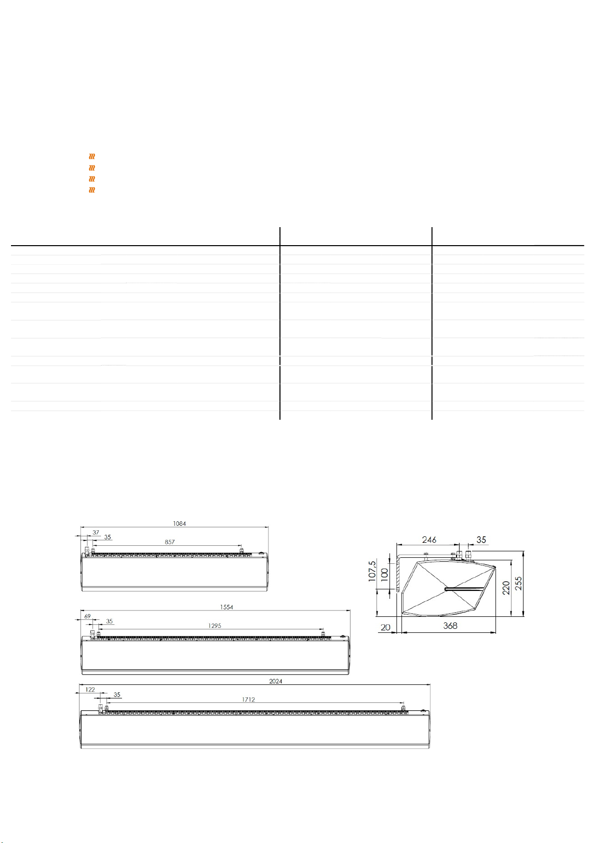
DIMENSIONS OF THE GUARD 100-150-200 W, E, C CURTAINS

Operation and Maintenance Documentation GUARD v202301
GUARD 100-150-200 E Air curtains with electric heater
GUARD E series (with electric heater) is based on a new type of PTC electric coils It is a modern and safe solution, additional
advantages of PTC heaters
Lack of voltage on the surface of the electric coil
Significantly lower coil temperature in comparison to the old type of electric
heaters (e.g. heating wires, spirals)
Large heat exchange surface (surface of contact of the heat exchanger with
heated air)
Fully automatic heat control depending on airflow
Complete elimination of the risk of a system overheating due to self-
regulating heating modules (heat capacity automatically reduces when airflow
goes down)
Low energy consumption
3. HEAT OUTPUT RANGES GUARD W
0 5 10 15 20 0 5 10 15 20 0 5 10 15 20 0 5 10 15 20 0 5 10 15 20
heat output kW 6,6 5,6 4,6 3,6 2,6 9,0 7,9 6,9 5,8 4,8 11,3 10,3 9,2 8,1 7,1 13,7 12,6 11,5 10,5 9,4 16,0 14,9 13,9 12,8 11,7
outlet air temperature
°
C
11,4 14,9 18,3 21,9 25,4 14,9 18,3 21,8 25,2 28,7 18,4 21,8 25,2 28,7 32,1 21,9 25,3 28,7 32,1 35,5 25,4 28,8 32,2 35,6 39,0
water flow m
3
/h 0,2 0,2 0,2 0,1 0,1 0,4 0,3 0,3 0,2 0,2 0,5 0,4 0,4 0,3 0,3 0,6 0,5 0,5 0,4 0,4 0,7 0,6 0,6 0,5 0,5
pressure drop kPa 1,0 1,0 0,6 0,6 0,3 2,0 2,0 1,0 1,0 1,0 4,0 3,0 2,0 2,0 1,0 5,0 5,0 4,0 3,0 2,0 7,0 6,0 5,0 5,0 4,0
heat output kW 5,9 5,0 4,2 3,3 2,4 7,9 7,0 6,1 5,3 4,4 10,0 9,1 8,2 7,2 6,3 12,0 11,1 10,2 9,2 8,3 14,0 13,1 12,2 11,2 10,3
outlet air temperature
°
C
12,5 15,8 19,1 22,4 25,8 16,4 19,6 22,9 26,2 29,5 20,3 23,5 26,8 30,0 33,3 24,2 27,4 30,6 33,9 37,1 28,0 31,3 34,5 37,7 40,9
water flow m
3
/h 0,2 0,2 0,1 0,1 0,1 0,3 0,3 0,2 0,2 0,2 0,4 0,4 0,3 0,3 0,2 0,5 0,4 0,4 0,4 0,3 0,6 0,5 0,5 0,5 0,4
pressure drop kPa 1,0 1,0 0,5 0,5 0,2 2,0 2,0 1,0 1,0 0,0 3,0 2,0 2,0 1,0 1,0 4,0 3,0 3,0 2,0 2,0 6,0 5,0 4,0 4,0 3,0
heat output kW 5,3 4,5 3,8 3,0 2,3 7,0 6,3 5,5 4,7 3,9 8,8 8,0 7,2 6,4 5,6 10,5 9,7 8,9 8,1 7,3 12,2 11,4 10,6 9,8 9,0
outlet air temperature
°
C
13,7 16,8 19,9 23,0 26,2 18,0 21,1 24,1 27,2 30,3 22,3 25,3 28,4 31,5 34,5 26,6 29,6 32,7 35,7 38,8 30,9 33,9 36,9 40,0 43,0
water flow m
3
/h 0,2 0,2 0,1 0,1 0,1 0,3 0,2 0,2 0,2 0,1 0,3 0,3 0,3 0,2 0,2 0,4 0,4 0,4 0,3 0,3 0,5 0,5 0,4 0,4 0,4
pressure drop kPa 1,0 0,8 0,5 0,5 0,2 1,0 1,0 1,0 0,7 0,6 2,0 2,0 1,0 1,0 1,0 3,0 3,0 2,0 2,0 1,0 4,0 4,0 3,0 3,0 2,0
0 5 10 15 20 0 5 10 15 20 0 5 10 15 20 0 5 10 15 20 0 5 10 15 20
heat output kW 13,5 11,7 10,0 8,2 6,4 17,4 15,6 13,8 12,1 10,3 21,3 19,5 17,7 15,9 14,1 25,1 23,3 21,6 19,7 18,0 29,0 27,2 25,4 23,6 21,8
outlet air temperature
°
C
11,9 15,4 18,9 22,5 26,0 15,1 18,6 22,1 25,7 29,2 18,3 21,8 25,3 28,9 32,4 21,5 25,0 28,6 32,0 35,6 24,7 28,2 31,7 35,2 38,7
water flow m
3
/h 0,5 0,4 0,3 0,2 0,2 0,6 0,6 0,5 0,4 0,3 0,8 0,7 0,7 0,6 0,5 1,0 0,9 0,8 0,7 0,7 1,2 1,1 1,0 0,9 0,8
pressure drop kPa 4,0 3,0 2,0 1,0 1,0 8,0 6,0 4,0 3,0 2,0 12,0 10,0 8,0 6,0 5,0 17,0 14,0 12,0 10,0 8,0 22,0 19,0 17,0 14,0 12,0
heat output kW 12,5 10,9 9,3 7,8 6,1 16,1 14,4 12,8 11,2 9,6 19,6 17,9 16,3 14,7 13,1 23,1 21,4 19,8 18,2 16,6 26,5 24,9 23,3 21,6 20,0
outlet air temperature
°
C
12,7 16,1 19,5 22,9 26,3 16,2 19,6 23,0 26,4 29,8 19,7 23,1 26,5 29,9 33,2 23,2 26,5 29,9 33,3 36,7 26,6 30,0 33,4 36,7 40,1
water flow m
3
/h 0,4 0,4 0,3 0,2 0,2 0,6 0,5 0,4 0,4 0,3 0,7 0,7 0,6 0,5 0,5 0,9 0,8 0,8 0,7 0,6 1,1 1,0 0,9 0,8 0,8
pressure drop kPa 4,0 3,0 2,0 1,0 0,6 6,0 5,0 4,0 3,0 2,0 10,0 8,0 6,0 5,0 4,0 14,0 12,0 10,0 8,0 7,0 18,0 16,0 14,0 12,0 10,0
heat output kW 11,0 9,7 8,4 7,0 5,7 14,0 12,6 11,3 9,9 8,6 16,9 15,5 14,2 12,9 11,5 19,8 18,4 17,1 15,7 14,4 22,7 21,3 20,0 18,6 17,3
outlet air temperature
°
C
14,2 17,4 20,6 23,7 26,9 18,2 21,3 24,5 27,7 30,9 22,1 25,3 28,5 31,6 34,8 26,1 29,2 32,4 35,6 38,7 30,0 33,1 36,3 39,5 42,6
water flow m
3
/h 0,4 0,3 0,2 0,2 0,1 0,5 0,4 0,4 0,3 0,3 0,6 0,6 0,5 0,4 0,4 0,8 0,7 0,6 0,6 0,5 0,9 0,8 0,8 0,7 0,6
pressure drop kPa 3,0 2,0 1,0 1,0 0,6 5,0 4,0 3,0 2,0 1,0 7,0 6,0 5,0 4,0 3,0 10,0 8,0 7,0 6,0 5,0 13,0 11,0 10,0 8,0 7,0
0 5 10 15 20 0 5 10 15 20 0 5 10 15 20 0 5 10 15 20 0 5 10 15 20
heat output kW 19,5 17,2 14,8 12,4 9,9 24,7 22,3 19,9 17,5 15,1 29,8 27,4 25,0 22,6 20,2 34,9 32,5 30,1 27,7 25,3 40,0 37,6 35,2 32,8 30,4
outlet air temperature
°
C
12,5 16,0 19,5 23,0 26,5 15,7 19,2 22,7 26,2 29,7 18,9 22,4 25,9 29,4 32,9 22,1 25,6 29,1 32,6 36,1 25,2 28,7 32,2 35,7 39,2
water flow m
3
/h 0,7 0,6 0,5 0,4 0,2 0,9 0,8 0,7 0,6 0,5 1,1 1,0 0,9 0,8 0,7 1,4 1,2 1,1 1,0 0,9 1,6 1,5 1,4 1,3 1,2
pressure drop kPa 9,0 6,0 4,0 3,0 1,0 15,0 12,0 9,0 7,0 5,0 22,0 19,0 15,0 12,0 9,0 32,0 27,0 23,0 19,0 15,0 42,0 37,0 32,0 27,0 23,0
heat output kW 18,2 16,0 13,8 11,7 9,4 22,8 20,7 18,5 16,3 14,1 27,5 25,3 23,1 20,9 18,8 32,1 29,9 27,7 25,5 23,4 36,6 34,5 32,3 30,1 27,9
outlet air temperature
°
C
13,3 16,7 20,1 23,5 26,8 16,8 20,2 23,6 27,0 30,3 20,3 23,7 27,0 30,4 33,8 23,7 27,1 30,5 33,8 37,2 27,1 30,5 33,9 37,3 40,6
water flow m
3
/h 0,6 0,5 0,4 0,3 0,2 0,8 0,7 0,6 0,5 0,4 1,0 0,9 0,8 0,7 0,6 1,2 1,1 1,0 0,9 0,8 1,4 1,3 1,2 1,1 1,0
pressure drop kPa 7,0 5,0 4,0 2,0 1,0 12,0 10,0 7,0 5,0 4,0 19,0 16,0 13,0 10,0 8,0 26,0 22,0 19,0 16,0 13,0 35,0 30,0 26,0 22,0 19,0
heat output kW 15,9 14,1 12,3 10,5 8,7 19,8 18,0 16,2 14,4 12,6 23,6 21,8 20,0 18,2 16,4 27,4 25,6 23,8 22,0 20,2 31,2 29,4 27,6 25,8 24,0
outlet air temperature
°
C
15,0 18,1 21,3 24,4 27,5 18,9 22,1 25,2 28,4 31,5 22,9 26,0 29,2 32,3 35,5 26,8 29,9 33,1 36,2 39,4 30,7 33,8 37,0 40,1 43,3
water flow m
3
/h 0,5 0,4 0,4 0,3 0,2 0,7 0,6 0,5 0,4 0,4 0,8 0,8 0,7 0,6 0,5 1,0 0,9 0,9 0,8 0,7 1,2 1,1 1,0 1,0 0,9
pressure drop kPa 5,0 4,0 3,0 2,0 1,0 9,0 7,0 5,0 4,0 3,0 13,0 11,0 9,0 7,0 5,0 18,0 16,0 13,0 11,0 9,0 24,0 21,0 18,0 16,0 13,0
inlet air temperature
90/70
inlet/outlet water temperature
inlet air temperature
GUARD 200W
inlet/outlet water temperature 50/30 60/40 70/50 80/60
inlet air temperature
GUARD 150W
inlet/outlet water temperature 50/30 60/40 70/50 80/60
GUARD 100W
90/70
90/70
III - max air flow - 3600 m3/h
II - mid air flow - 3000 m3/h
I - low air flow - 2200 m3/h
70/50 80/60
III - max air flow - 4800 m3/h
II - mid air flow - 4000 m3/h
I - low air flow - 2900 m3/h
III - max air flow - 2000 m3/h
II - mid air flow - 1550 m3/h
I - low air flow - 1200 m3/h
50/30 60/40

Operation and Maintenance Documentation GUARD v202301
4. GENERAL AND SAFETY PRINCIPLES
The GUARD air curtains are manufactured in compliance with the rules and standards concerning quality, ecology, utility, and
work comfort. Before starting the device be sure to read the Manual carefully.
The GUARD air curtains are delivered ready-to-use in a cardboard package that is to protect from any mechanical damage. The
package consists of the device, the Manual (Operation and Maintenance Documentation), and the Guarantee. If the optional
automatic control is ordered, it shall be delivered in a separate package. Make sure all the aforementioned elements are in the
package immediately after delivery. In the absence of any element, please fill in the suitable carrier document.
NOTICE!
Do not use the curtain in rooms containing any flammable and/or combustible substances, biological substances, or in
environments with corrosive air components.
Do not use the curtain in rooms with relative humidity above 80%
Do not leave the curtain ON unattended for long periods
Do not use the curtain without proper grounding
Do not turn the curtain on without a protective cover in place
Before conducting any maintenance or cleaning work or during the break-in operation for an extended period, make
sure you unplug the power cable
To connect the air curtain, use a supply cable with a fork that protects against unintended disconnecting from the
power
When the air curtain is connected directly to the cable, please make sure there is a splitter protecting against any
undesired disconnecting
Pay special attention while transporting the device not to damage the casing
When the device is being operated, ensure the safety rules following the labor standards relating to the operation of
any electrical devices
Do not place any objects on the curtain or reduce the airflow to ensure fire safety and if sparks or a damaged supply
cable are noticed, discontinue the operation immediately
The electricity network, to which the curtain is connected, should be protected against overloading and short circuit
CAUTION!
To avoid the serious danger of electric shock, installation must be performed by a qualified electrician
To avoid the danger of electric shock disconnect the power supply before conducting any repair or maintenance work
Any leakage repairs of the heating medium in the device, of which pipes are under pressure, are strictly prohibited
A cut-off/stop valve must be used to supply a heating medium
It is prohibited to connect the grounding-type plug to water pipes, gas tubes, lightning conductors, telephone or
antenna network
Wait for at least 3 hours before connecting the device to the power supply if the temperature while transporting is
below zero
5. INSTALLATION
When deciding on the air curtain position you should take into account such factors as:
Ease of access for servicing,
Access to water and electricity supplies
It is recommended to install the air curtain in position above the entrance opening, on the wall or under the ceiling, on support
pins or horizontal mounting brackets. It is also possible to mount it vertically to a wall or other structure using vertical mounting
brackets.
It’s important to make sure that the unit is properly leveled. In case of positioning in a different way than horizontally or
vertically, during installation, damage to the fan may occur and as a consequence malfunction of the unit.
Inlets and outlets cannot be blocked by any objects. When installing the curtains, keep in mind that you will have free access to
the control panel. With larger door openings, it is possible to mount more curtains of the same type, one by one, to create an
uninterrupted airflow. The curtain is permanently mounted in either a horizontal or vertical position (on the left/right side of the
entrance).
Curtain connection should be done in a serviceable manner, manual shut-off valves should be installed on both nozzles to
enable disconnection. In the case of a solenoid valve (option - automatics), it must be connected to the water outlet of the
device, otherwise, it may be damaged. When tightening the pipeline to the exchanger, the heater connection must be protected
against torque (which may cause leakage in the exchanger).
NOTICE !
Before mounting the device, read the manual carefully and adhere to the rules concerning the mounting
procedures. Not applying to the rules may result in the inappropriate functioning of the device and the loss of
the guarantee rights.
Pay special attention when working with electrical elements of the device.

Operation and Maintenance Documentation GUARD v202301
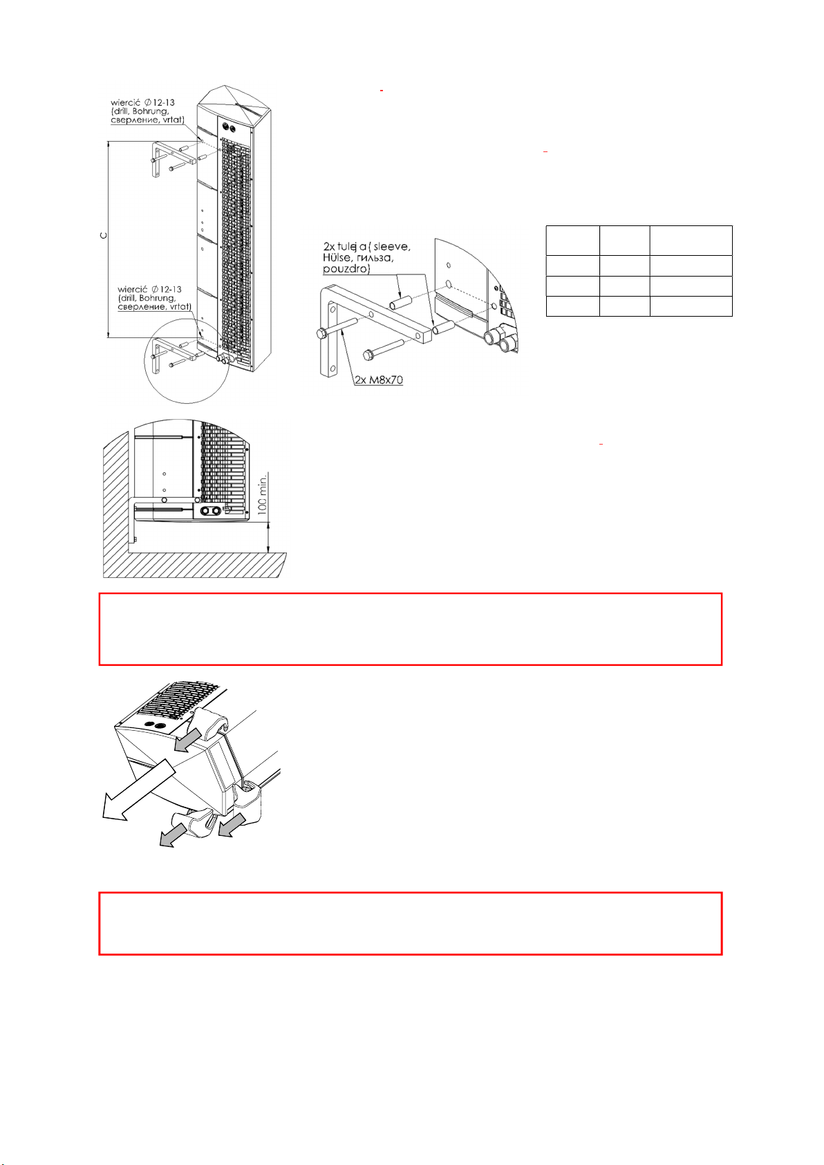
Horizontal installation under the ceiling using mounting pins
Installation under the ceiling is done by using 4 M8 pins. To hang the device on the pins, drill holes Ø 8-9mm in the EPP
housing directly in front of the existing holes in the steel inlet grille. The exact location is indicated by special tags on the EPP
housing. The pins should be screwed into the nippers at a depth of 9 mm.
Drawing below shows the position of the mounting holes for the pins
Curtain size
A(mm)
C(mm)
Nuber of pins M8
100 72 857 4
150 104 1295 4
200 157 1712 4
Wall installation by means of a horizontal brackets
The curtain can be mounted to the wall in a horizontal position using 2 mounting
brackets to the horizontal system. In the brackets there are Ø9mm holes for M8
screws. In the EPP housing, drill holes Ø 12-13mm in front of existing holes in the
steel intake grille. The exact location is indicated by the special tags on the EPP
housing and the figure below. Then insert the spacer sleeves into the holes and fix
the brackets. Screw the remaining screws into the nuts under the steel intake grille
so that both grips are in one plane. Locknuts under the handles are used to secure
the screws from unscrewing.
Operation and Maintenance Documentation GUARD v202301
Installation using brackets for vertical mounting
It is also possible to install the unit vertically with the engine downwards and upwards.
Two vertical mounts are used for this purpose. In the brackets there are Ø9mm holes for
M8 screws. In the EPP housing, drill holes Ø 12-13mm in front of existing holes in the
steel intake grille. The exact location is indicated by special tags on the EPP housing and
the figure below. Then insert the spacer sleeves into the holes and fix the brackets.
Screw the remaining screws into the nuts under the steel intake grille so that both grips
are in one plane. Locknuts under the handles are used to secure the screws from
unscrewing.
Connection of heating medium
The connection of the heating medium to the heat curtain, using G 1/2" threaded
connections should be made based on a design by an authorized designer. If the air
curtain is connected to a district heating network without a mixing unit, a water filter is
required. The direction of connection to the water heater does not affect air curtain
works.
In the case of horizontal and vertical mounting with nozzles at the top, the exchanger is
vented through the nozzles. If the device is mounted vertically with nozzles at the
bottom to vent the exchanger, use a vent that is located on the exchanger collector on
the engine side.
Connecting the power supply and control system of the curtain
To connect the power supply, control and/or bleed the Exchange move out the right
lid, which is fastened with the lock to the lower steel housing and the main housing
EPP. The lid is disassembled in the direction shown by the arrows in the figure below.
The lid should be grasped in the following places indicated in the drawing and should
be gradually "released" from the locks for several millimeters. Cable entries for power
and control cables are located on the inlet grille.
Curtain
size C(mm)
Number of
brackets
100 857 2
150 1295 2
200 1712 2
ATTENTION !
It is necessary to ensure that the unit is properly leveled. When it is mounted in a position other than vertical
or horizontal there is a risk of fan damage and unit malfunction
The minimum distance between device and floor cannot be less than 100 mm
ATTENTION !
Ensure that no connection wire is clamped between the lid and the rest of the curtains before assembling the lid.

Operation and Maintenance Documentation GUARD v202301
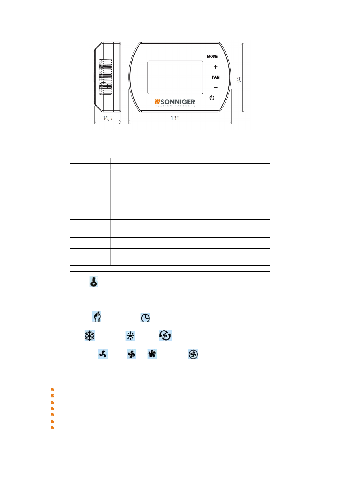
6. CONTROL PANEL
A set of automatic control may be used (powered 230V) that consists of the following:
COMFORT NEW panel – including room thermostat and switch for regulation of 3 speeds of the fan.
One COMFORT panel may regulate up to 2 pcs of GUARD
2-way water valve with actuator; valve should be installed on a return stub of the heater
INTELLIGENT electronic control panel with an automatic speed controller, weekly program, and BMS communication.
One INTELLIGENT panel may regulate up to 2 pcs of GUARD
Splitter MULTI 6 - control up to 6 pcs of GUARD
The system is ready to start once the connections between the thermostat and the valve actuator are done, 230V power is
supplied to the thermostat and the fan’s motor is powered by the revs controlle.
COMFORT NEW panel description
OFF-I-II-III - switch and fan speed regulation
HEAT - the thermostat gives an operation signal to the actuator and fan, the fan turns off when the set
temperature is reached, the valve closes the water supply
FAN - device fan operation according to the thermostat, valves or electric heaters do not work
COOL - the thermostat gives an operation signal to the actuator and fan, the device starts to work
when the set temperature is reached
It is possible to use an additional change of the SR1 to SR1 CONST jumper position, in this case the fan can operate regardless
of the thermostat. Thermostatic operation is only for valves. In this case:
HEAT - fan operation regardless of the thermostat, valves work up to the set temperature
FAN - device fan operation, regardless of the thermostat, valves do not work
COOL - fan operation regardless of the thermostat, valves work from the set temperature
7. GUARD DOOR SWITCH
The GUARD (DC) door switch is an additional element for switching the curtain on/off, depending on the opening of the door.
It is designed for indoor installation. It includes:
Relay cabinet - reed relay switchboard
Reed relay - Reinforcement for door-fitting, hermetic magnetic switch, consisting of a movable and fixed element
Scheme of the relay cabinet – reed relay interface
When installing the GUARD door switch, remove the factory-made jumper:
NC-1 for curtain GUARD W (curtain with a water heater) / GUARD C (curtain without a water heater)
NC-COM for curtain GUARD E (curtain with an electric heater)
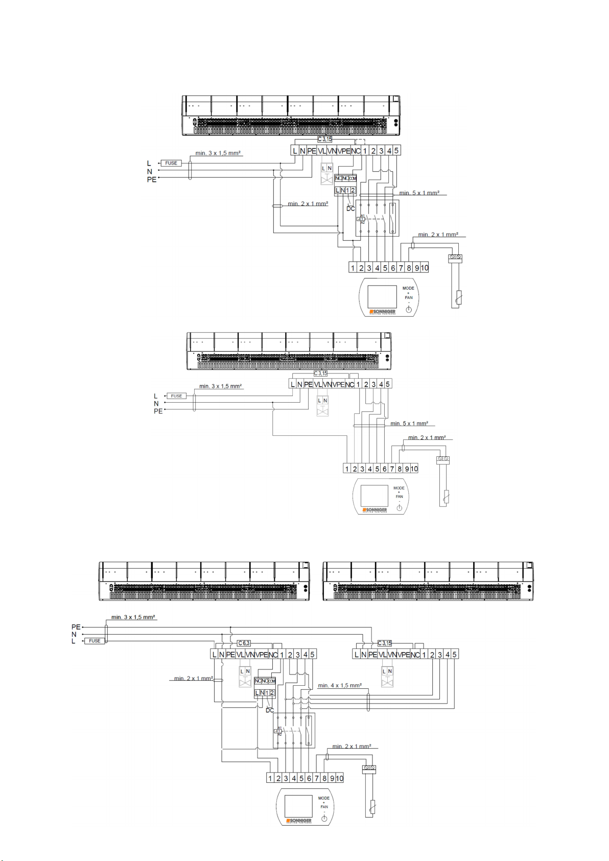
8. DIAGRAMS OF ELECTRICAL CONNECTIONS
The electrical network to which the curtain will be connected should protect against overheating and short-circuiting. It is
necessary to protect the air curtain by grounding. Electrical installation and connection to the air curtain must be following
applicable building codes and regulations, electrical connection should be carried out by a qualified person familiar with the
above instruction. The fan motor has standard internal thermal protection to protect the motor from overheating. The set does
not include: a power cord, or main switch
*diameter and length of the cable should be following local regulations (some deviations are acceptable)
Operation and Maintenance Documentation GUARD v202301
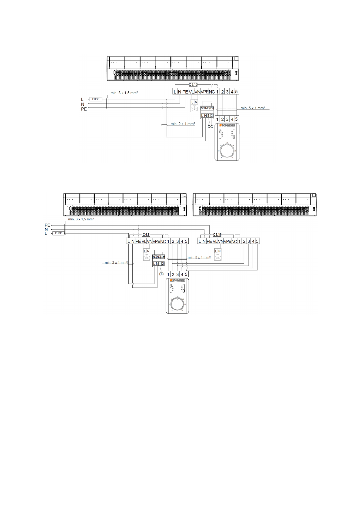
8.1 Diagram of connecting one GUARD 100-150-200 W (water heater) and C (without heater) to the COMFORT panel
*The unit set does not consist of: a master switch, a fuse, a feeding cable
In case of working without DOOR SWITCH the bridge between terminal NC-COM need to be keep.
8.2 Diagram of connecting two GUARD 100-150-200 W (water heater) and C (without heater) to one COMFORT panel
*The unit set does not consist of: a master switch, a fuse, a feeding cable
In case of working without DOOR SWITCH the bridge between terminal NC-COM need to be keep.
In the MASTER curtain between the L-NC terminals, replace the factory-made fuse (C 3.15) with C 6.3 (for work with DOOR
SWITCH remove the bridge between terminal NC-1)
Operation and Maintenance Documentation GUARD v202301
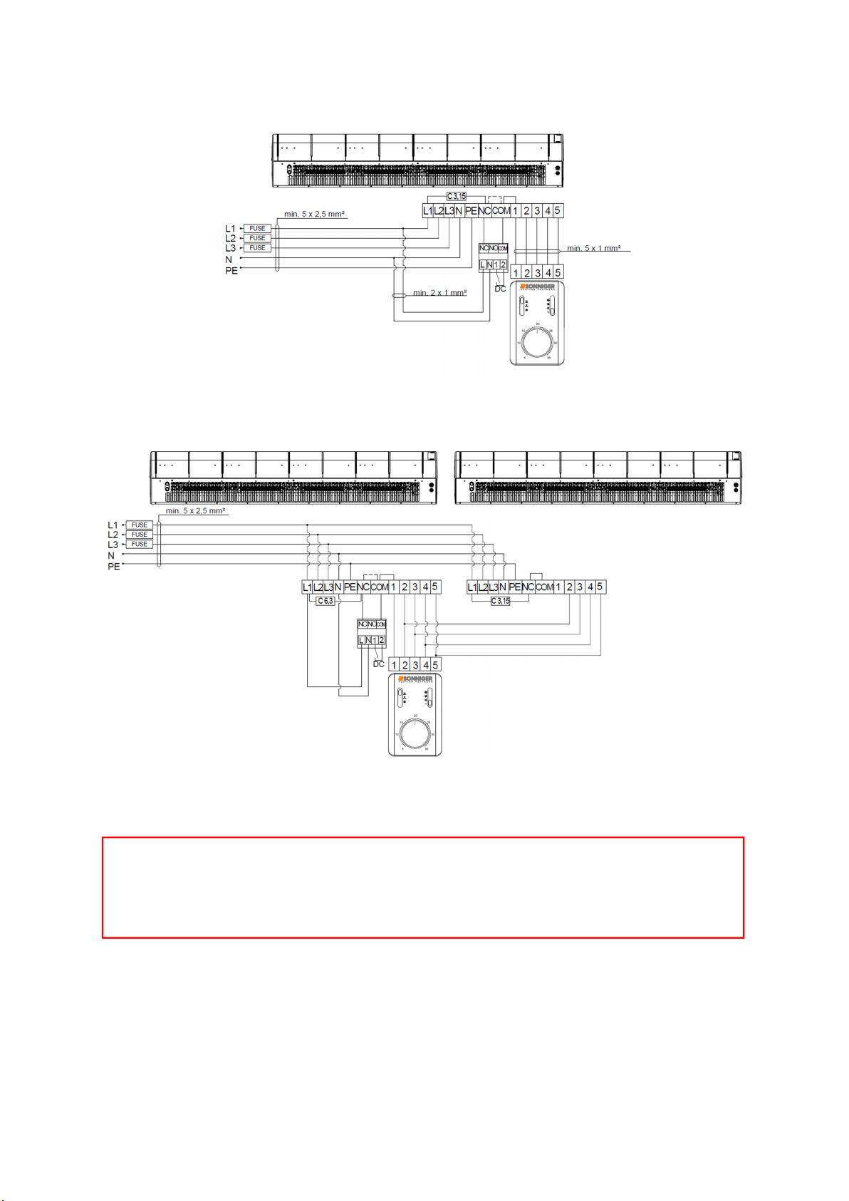
ATTENTION!
PTC heaters power supply 3x400V/50Hz or 3x400V/60Hz
min. 5 x 2,5 mm for G100E; (B16)
min. 5 x 4 mm for G150E; (B20)
min. 5 x 6 mm for G200E; (B25)
8.3 Diagram of connection of one GUARD 100-150-200 E curtain (electric heater) to the COMFORT panel
*The unit set does not consist of: a master switch, a fuse, a feeding cable
In case of working without DOOR SWITCH the bridge between terminal NC-COM need to be keep.
8.4 Diagram of connection of two GUARD 100-150-200 E curtain (electric heater) to one COMFORT panel
*The unit set does not consist of: a master switch, a fuse, a feeding cable
In case of working without DOOR SWITCH the bridge between terminal NC-COM need to be keep.
In the MASTER curtain between the L-NC terminals, replace the factory-made fuse (C 3.15) with C 6.3 (for work with DOOR
SWITCH remove the bridge between terminal NC-COM)
Operation and Maintenance Documentation GUARD v202301
8.5 Connection diagram of GUARD 100-150-200 W and C with INTELLIGENT
8.5.1 With DOOR SWITCH
8.5.2 Without DOOR SWITCH
8.6 Diagram of connecting two GUARD 100-150-200 W and C to the INTELLIGENT panel
8.6.1 With DOOR SWITCH

Operation and Maintenance Documentation GUARD v202301
In the MASTER curtain between the L-NC terminals, replace the factory-made fuse (C 3.15) with C 6.3 (for work with DOOR
SWITCH remove the bridge between terminal NC-COM).
8.6.2 Without DOOR SWITCH
8.7 Diagram of connecting one GUARD 100-150-200 E (electric heater) to the INTELLIGENT panel
8.7.1 With DOOR SWITCH

Operation and Maintenance Documentation GUARD v202301
8.7.2 Without DOOR SWITCH
8.8 Diagram of connecting two GUARD 100-150-200 E (electric heater) to the INTELLIGENT panel
8.8.1 With DOOR SWITCH
In the MASTER curtain between the L-NC terminals, replace the factory-made fuse (C 3.15) with C 6.3 (for work with DOOR
SWITCH remove the bridge between terminal NC-COM).

Operation and Maintenance Documentation GUARD v202301
ATTENTION!
PTC heaters power supply 3x400V/50Hz or 3x400V/60Hz
min. 5 x 2,5 mm for G100E; (B16)
min. 5 x 4 mm for G150E; (B20)
min. 5 x 6 mm for G200E; (B25)
8.8.2 Without DOOR SWITCH
In the MASTER curtain between the L-NC terminals, replace the factory-made fuse (C 3.15) with C 6.3.
9. OPERATION AND MAINTENANCE
The engine and fan of the GUARD air curtains are maintenance-free devices but regular check-ups are advised, especially the
motor and bearing (the fan’s rotor should rotate freely, free from any axial and radial throws/run-outs and undesired
knocks/rattles.
The heat exchanger requires systematical cleaning of all dirt/impurities off. Before the start of the heating period, the heat
exchanger is advised to be cleaned with compressed air directed to the air outlets; there is no need for dismantling the device.
Pay special attention when cleaning the exchanger’s fin due to the high possibility of damaging them. If the fin is bent use a
special tool. If the device has not been used for a longer period, unplug it before the next use.
The heat exchanger is not equipped with any fire protection device. The heat exchanger may be damaged if the room
temperature goes below 0°C; anti-freeze liquid must be added to the water circulation/system. Anti-freeze liquid must be
appropriate for the material the exchanger is made of (copper) as well as other elements of the hydraulic system/circulation.
The liquid must be diluted with water accordingly to the manufacturer’s recommendation.
ATTENTION!
Any repair and maintenance work must be conducted with the power off and the heat input disconnected.
Only suitably qualified staff well acquainted with the safety regulations concerning handling an electrical device
must be employed when the device is being installed, started, and operated
In the event of a coolant leak, when the water system is under pressure, any repairs of the leakage are strictly
prohibited.
Any repairs to the device must be conducted only if the device is disconnected from the power supply.
If the device being operated gives a metallic clatter, or vibration or the level of noise is increasing, check if the
mounting of the fan has not become loose – in case of any problems contact the installer of the device or the
SONNIGER Authorized Service immediately.
Operation and Maintenance Documentation GUARD v202301
10 PANEL INTELLIGENT WIFI – programmable controller manual
Panel Intelligent WIFI controls actuators/valves and automatically regulates the fan’s speed depending on the required room
temperature. The lower temperature in the room the higher the air output is set. Fan speed changes automatically at a lower
rate when the temperature in a room gets closer to the desired one. Intelligent WIFI allows to management work of the device
via the mobile app TUYA SMART.
Functions
Panel INTELLIGENT is designed for the SONNIGER products
Weekly thermostat (5/1/1 days)
Automatic or manual 3-step fan speed adjustment.
Control room temperature (by opening/closing the valve, or by
adjusting air volume automatically).
Antifreeze mode- protection against dropping room
temperature below critical level 5 ~ 15 °C.
Possibility to connect external NTC temperature sensor.
BMS communication by MODBUS protocol
Wireless control via the TUYA SMART app
Dry contact feedback
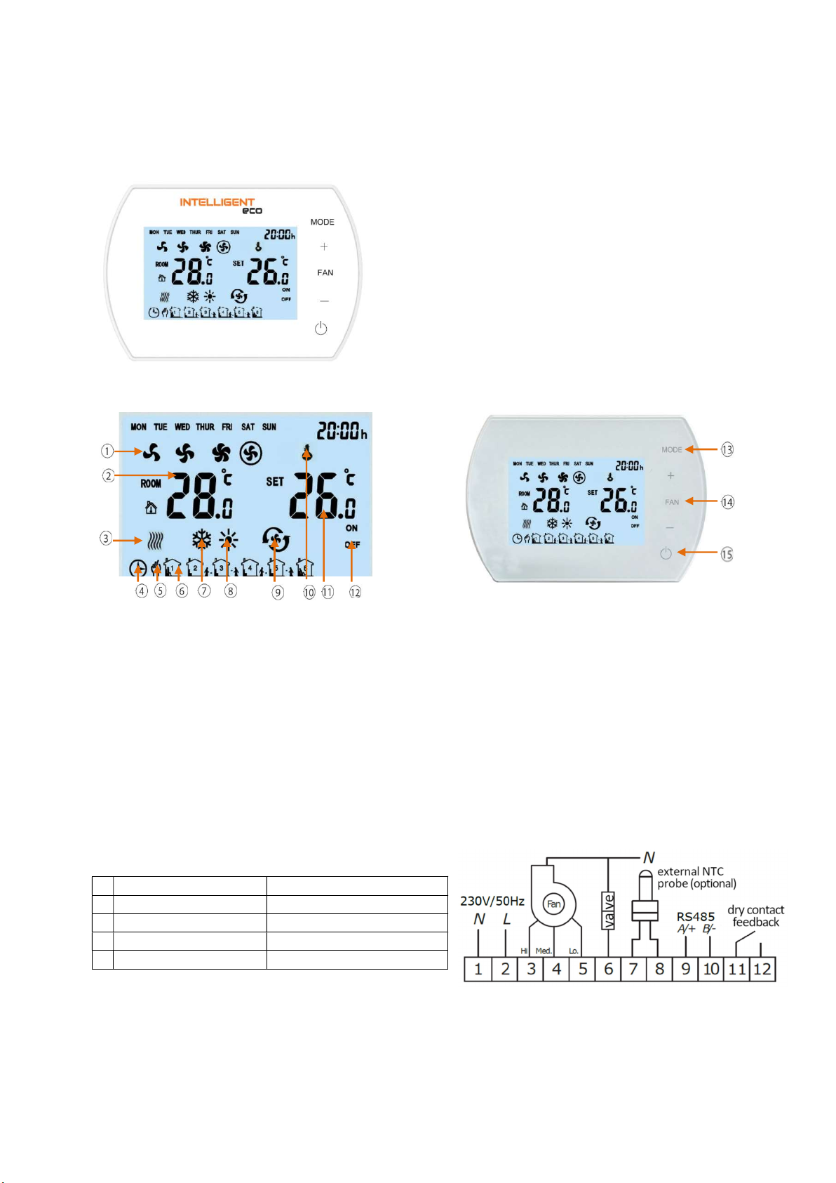
Panel description
1. Fan Speed: LOW, MED, HI and AUTO
2. ROOM TEMP. or NTC EXTERNAL SENSOR TEMP. (measured
temperature)
3. Anti-freeze indication
4. Automatic programable mode
5. Manual mode
6. 6 Time Zones for each day
7. Cooling Mode
8. Heating Mode
9. Ventilation Mode
10. Buttons Lock
11. SET TEMP. (desired room temperature)
12. ON/OFF status of time zones
Technical parameters
1 Power supply 230VAC/50Hz
2 Temperature setting range 5°C 40°C
3 Temperature working range -10°C 60°C
4 IP class 20
5 Temperature sensor Internal / external NTC (optional)
13
MODE
Press shortly to select manual or automatic
mode Press and hold for 3 s and select colling,
heating or ventilation mode
14 FAN Press shortly and select fan speed: Low, Med,
High or Auto
15 ON/OFF INTELLIGENT Panel
Operation and Maintenance Documentation GUARD v202301
Dimensions
Settings menu
When Panel Intelligent is switched off, press and hold MODE for 5 seconds
To change option use MODE button.
To change value use +/- buttons.
Setting menu
Option
Value
1
Temperature calibration
–
9°C ~ +9°C
2 EEPROM
0:
no memory
1: memory
3 Fan status
C1:
Thermostatic mode
C2: Continuous mode
4 Temperature sensor
0: Internal Sensor
1: External Sensor NTC (optional)
5 Antifreeze
0:
Off
1: On
6
Antifreeze range
+5°C ~ +15°C
7 ALARM
0: disable
1: enable
8 Drycontact
0: NO
1: NC
9 MODBUS
0: disable
1: enable
10
BMS speed
0
-
2400 / 1
-
9600 / 2
-
19200
11
Modbus ID
1~247 (01~F7)
Button lock / unlock
To LOCK buttons press and hold + and then – and hold both of them for 5 seconds.
To UNLOCK buttons press and hold + and then – and hold both of them for 5 seconds.
Press MODE
Change on manual mode or automatic mode
Hold MODE for 5 seconds
Change to cool mode , heating mode , ventilation
Press FAN
Change of the fan speed low , medium , high , automatyczna
Hold FAN for 5 seconds
Manual callendar programming Monday – Friday, Saturday, Sunday 6 settings per day
BMS Functions
Setting/Reading work parameters
Work/Stop conditions
Weekly program
Temperature
Fan speed
Heating, ventilation, cool mode
Antifreeze mode
Operation and Maintenance Documentation GUARD v202301
WIFI functions
Setting/Reading work parameters
Work/Stop conditions
Weekly program
Temperature
Fan speed
Heating, ventilation, cool mode
CONNECTION INTELLIGENT WIFI WITH TUYA SMAR APP
1. Download the Tuya Smart app (available at App Store and Google Play)
2. The Control panel connects to the power supply and device, Panel INTELLIGENT should stay off
3. Turn on the Tuya app and follow the instruction in the app
4. For the connection process, please enable the GPS and Bluetooth in the phone
5. To activate the paring mode in the INTELLIGENT Panel tap twice and hold the “+” symbol for 5 seconds until the
“SA” symbol shows on the left side of the screen
6. Choose the „Add device” function, and the app should find the control panel automatically, press the "Add" button,
and after completing the configuration process, press "Next" and "Finished"
7. In the absence of the "Add" function, select the "Small devices" tab and the "Thermostat (Wi-Fi)" function. After that
enter the data to connect to the selected WiFi network and confirm, and then "Blink slowly".
8. A screen will be displayed with information about searching for a device. After detecting the driver, the connection
process is automatic. after completing the configuration process, press "Next" and "Finished"
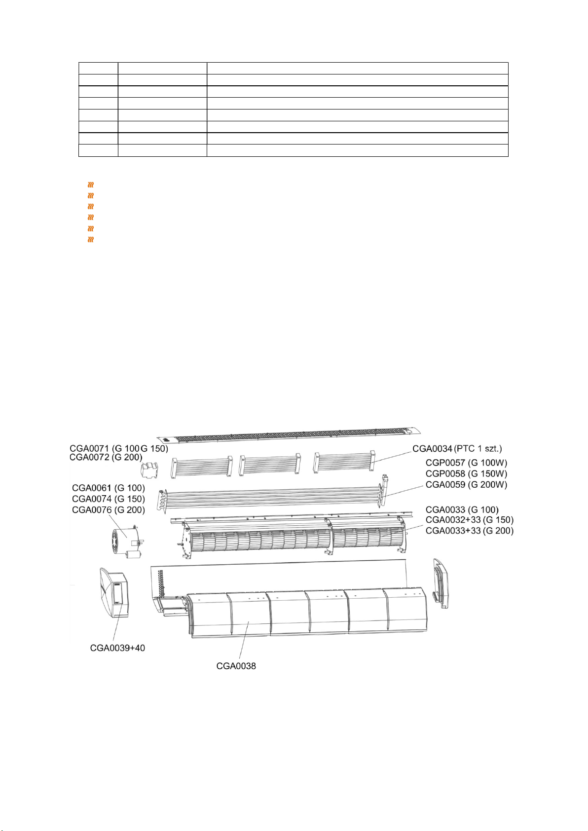
SPARE PARTS
No.
Setting
Paremeters
1
Working
Mode
RS485 Semi
-
duplex; PC or main controller is master; thermostat is slave
2
Interface
A(+),B(
-
), 2 wires
3
Baud Rate
0
-
2400 / 1
-
9600 / 2
-
19200
4
Byte
9 bits in total: 8 data bit + 1 stop bit
5
Modbus
RTU Mode
6
Transmittion
RTU (
Remote Terminal
Unit
) format
(
please refer to MOBUS instruction)
7 Thermostat address 1-247;(0 is broadcast address and stand for all thermostat without response)

Operation and Maintenance Documentation GUARD v202301
COMPLIANCE WITH WEEE 2012/19 / EU
In accordance with applicable legal regulations, at the time of purchasing new electrical or electronic equipment with the
following mark:
REMEMBER IT IS FORBIDDEN TO PLACE THE WORN EQUIPMENT WITH OTHER WASTE
For information on the waste collection system of electrical and electronic equipment, please contact your
distributor
GUARANTEE TERMS AND CONDITIONS
§ 1 Guarantee Scope
1. This Guarantee covers material defects of the device which make its functioning impossible. This Warranty does not
extend to the installation and maintenance works.
2. The Guarantee for the product sold by the Seller covers 24 months. The guarantee period commences upon the delivery of
the device to the Buyer specified in the sales invoice. The warranty covers any parts/components specified in the scope of
the delivery.
3. Products delivered by third persons are not guaranteed by this supplier.
4. Devices may be started and serviced only by qualified persons trained in the areas of maintenance and operation of the
device. Any operations related to starting, maintenance, and repairs must be noted that such operations have occurred in
the Guarantee Card.
5. The precondition for issuing the Guarantee by the manufacturer is the assembly and activation of the device following the
Operation and Maintenance Documentation not later than 6 months after the date of the purchase.
6. The product is guaranteed for a full period of warranty only if service works implied in the Operation and Maintenance
Documentation for the device specified in the ‘Maintenance’ section are carried out. All services related to the maintenance
of the device are carried out at the User’s cost and expense.
7. The provision of warranty services does not cease or suspend the duration of the Warranty. The warranty for replaced or
repaired parts/elements shall end with the expiry of the Guarantee for the device.
§ 2 Warranty Exclusions/Disclaimers
1. The Warranty does not extend to the mechanical damages and damages to electrical parts caused by improper use,
transport, abnormal voltage, or other damages arising from a product defect. For the above reasons, the Warranty is
solely limited to the replacement of parts/components having construction defects that shall be delivered without any
additional costs only if the defective part/component has been returned.
2. The Warranty for devices does not apply when technical mistakes occurred during the procedures concerning installation,
regulation, and control including any of the following:
a) Defects caused by connecting a device to an inappropriately designed ventilation system that allows additional heat
loads that do not meet any standards and decrease the efficiency of the heat exchanger.
b) Defects caused by connecting to the components or parts that are part of the heating system but have not been
delivered by the Seller and whose inappropriate functioning harms the device’s functioning.
c) Defects caused by connecting spare parts to components that are not original parts.
d) Defects incurred by reselling the product by the first buyer/user to another buyer who dismantles/installs the device
that was previously installed and operated in a specific building and its conditions.
e) Defects caused by improper expertise and insufficient knowledge of the installer and technical staff who, improperly
carry out after-sale service of the device
f) Defects caused by special conditions of use that differ from typical/standard applications unless the parties (the Seller
and customer’s technical staff) have previously agreed otherwise in writing.
g) Defects incurred by natural disasters such as fire, explosions, and other incidents that may result in damages to
mechanical, electrical, and protection devices
h) Defects are caused by inappropriate cleaning of the technical facility or place where the device has been installed;
cleaning must take place periodically to suit the specific working conditions and the amount of dust.
i) Defects arised from the absence or improper cleaning of heat exchangers; cleaning must be done periodically to suit
the specific working conditions and the amount of dust.
j) Defects incurred by the inappropriate installation - inadequate for the low outside temperature of working conditions.
k) Defects incurred by the low temperature if no protection device is installed by the installing contractor to avoid:
low temperatures on electrical and mechanical parts such as valves, electric and electronic controlling devices,
water condensation and frost/ice near the device,
thermal shock of the heater and heat exchanger caused by sudden changes of the outside temperature.
§3. SONNIGER Poland is not liable to:
1. Current maintenance works, and inspections follow from Operation and Maintenance Documentation and device
programming.
2. Defects caused by banking of a device while waiting for the warranty service.
3. Any defects caused to the company’s property.

Operation and Maintenance Documentation GUARD v202301
§4. Complaint Procedure
1. In the event of a complaint under the Warranty conditions, the user may complain directly to the Distributor.
2. All repairs covered by the warranty shall be done as part of the activity of an installation company and Factory Service. All
repairs ensuing from the guarantee shall be done in a place where the device is installed.
3. Any services under the Warranty are to be carried out within 14 days from the date of request. In exceptional cases, the
deadline may be extended, especially if the warranty service requires ordering parts or components from subcontractors.
4. The user concerning the service activities is obliged to:
Allow having full access to the rooms where the devices were installed and provide the necessary facilities allowing
direct access to the device (lift, scaffolding, etc.) to do all the servicing covered by the guarantee.
Present the original of the Guarantee Card and VAT invoice recording the purchase,
Ensure safety while doing the servicing,
Allow starting works immediately after the arrival of the Service.
5. In order to make a complaint under the warranty it is necessary to deliver to the Distributor’s address the following
documents:
a) correctly filled-in complaint form that is available at the website of www.sonniger.com
b) copy of the Guarantee Card
c) copy of the proof-of-purchase - the sales invoice
6. The repair service including the replacement of the parts shall be done free of charge only if the representative of the
installing contractor or the Service claims that the defect or malfunctioning of the device is caused by the fault of the
producer.
7. Any costs (cost of repair, travel, and exchanged components) incurred due to the unjustified complaint, especially in the
situation when the representative of the Installing Contractor of the Factory Repair Service claims that defect/damage was
caused as a result of breaching the guidelines provided in the Operation and Maintenance Documentation or notices the
exclusions under §2 (Warranty exclusions) will be requested from the Buyer/Customer who reported the failure.
8. The Claimant is obliged to give a written confirmation of the service provided.
9. Sonniger Poland is entitled to refuse the warranty service if Sonniger Poland has not received full payment for the product
complained about under the Guarantee or any previous servicing activities.

Operation and Maintenance Documentation GUARD v202301
GUARANTEE CARD
INVESTEMENT: ……………………………………………………………………………
Device model:…………………………………………………………………………………………….…
Serial number:……………………………………………………………………………………………...
Date of purchase:……………………………………………………………………………….................
Start date: …………………………………………………………………………………………………..
Details of installation company:
Person activating the device:………………………………………………………………...
Name of company:………………………………………………………………………………………….
…………………………………………………………………………………………………………….….
Address:……………………………………………………………………………………………………..
Telephone:……………………………………………………………………………………………………
Signature of a person who has started the device:………………………………………………………
Installation works, check-ups/inspections, repairs:
Date The scope of installation works, inspections, repairs Signature and installation company stamp

Dokumentacja techniczno-ruchowa kurtyna standardowa GUARD v202301
Dokumentacja techniczno-ruchowa GUARD
SONNIGER S.A.
ul. Śląska 35/37, 81-310 Gdynia, Poland, infolinia 801 055 155, tel. + 48 58 785 34 80, www.sonniger.com
Sąd Rejonowy Gdańsk-Północ, VIII Wydział Gospodarczy Krajowego Rejestru Sądowego, KRS 0000966611, NIP 586 227 35 14
Regon 22154369 kapitał zakładowy: 1.655.000 PLN
Other manuals for GUARD
1
This manual suits for next models
9
Table of contents
Languages:
Other Sonniger Heater manuals

Sonniger
Sonniger GUARD Installation guide

Sonniger
Sonniger GUARDPRO Series Installation guide

Sonniger
Sonniger GUARD PRO Installation guide

Sonniger
Sonniger GUARD PRO Installation guide

Sonniger
Sonniger CR ONE Installation guide

Sonniger
Sonniger HEATER CONDENS Installation guide

Sonniger
Sonniger Heater R2 User manual

Sonniger
Sonniger Heater R1 User manual

Sonniger
Sonniger GUARD 100W Installation guide


