BeingHD E Series User manual
Fixed 4K2K HDMI Matrix Switcher E Series with EDID management
FIX-MANAGER-400-E
Version: V2.0.1
USER MANUAL
For the products color, please refer to the real product!

Safety Reminder
To protect the device and operating personnel from electrostatic discharge, you
need to check and ensure that the device is grounding well before the device is
powered on. Please observe the following when you install, use, maintain this
equipment.
Make sure the device ground connection.
Please use single-phase three wire system AC 220V power supply, and ensure all
transmission system is grounding well.
To protect operating personnel and the device,please turn off all power supplies
and pull the plug before moving the device or doing some specific works which need
to be done when the electricity is turned off . Please turn off the main power switch
on rainy days or when not in use for a long time.
Please do not put anything upon the cables, or tread the cables.
To avoid damaging the device, please turn off power supply before plugging cable
into the device or pulling cable from device. The damage caused by plugging/ pulling
cables without turning off power supply is outside the scope of the warranty.
The power of the device gives out heat when it works, so it’s necessary to keep
the work environment ventilated to protect the device from the damage caused by
over temperature.
Do not place the device in very cold or very hot places. Do not sprinkle any
corrosive chemicals or liquid on or around the device.
To avoid accident or any further damage ,non-professionals please do not
dismantle or maintain the device without permission.

1. Product Introduction
This is a new series of the fixed 4K2K HDMI matrix switcher, with EDID management on front
panel and control software, it can perfectly work with HDMI displays. Every HDMI input and
output supports 1080p Full HD up to 4K30 plus all 3D formats and HDCP compliant on all ports.
It can work with Blu-Ray players, Set-Top boxes, Home Theater PCs, and game consoles which
connect to an HDMI display. Supports RS-232, TCP/IP, 2-key front buttons and remote to
control.
2. Product Index
HDMI V1.4 supports: 4K2K@30Hz, 1080P 3D@60Hz
Deep Color support 48/36/30/24-bit
Supports LPCM 7.1CH, Dolby True HD, Dolby Digital Plus and DTS-HD Master Audio
transmission
Allows any source to be displayed on multiple displays at the same time
Allows any HDMI display to view any HDMI source at any time
Supports 23 formats independent EDID, including 4-output EDID, 15 internal EDID.
Supports RS-232, remote control, on-panel control and TCP/IP Control
Front-panel LCD display for status feedback
3. Operation and connection
1. Connect signal source such as Blu-ray player, game controller, A/V receiver, cables,
satellite receiver etc. to the HDMI input port of the matrix. Please do not hot plug! Please
turn off power supply before plugging /pulling cables and operate carefully. Connecting
signal sources with power-on may cause circuit damage.
2. Connect the HDMI output port of the matrix to HD display or HD projector with HDMI
input port. Notice: It ’s better to use High-Speed HDMI Cable when the transmission
distance is too long.
3. Firstly power on the signal source,then the matrix(with power supply),finally devices
connected to the output port .
4. After power on, every display device should display the specified signal. Make sure the
devices are normal. Testing switching functions by matched IR remote control. If one of the

displays failed to receive signal correctly, enter the menu of display, adjust the resolution
from MIN to MAX until the signal is displayed normally. A 24 Hz refresh rate may work better
than 60 Hz or higher.
4. Specification
Name
FIXED 4K2K HDMI MATRIX SWITCHER
Resolution ratio
Supports:480i, 576i, 480p, 576p, 720p, 1080i,
1080p@24/30/50/60Hz, 4K@30Hz, 1080P3D@60Hz
Input ports
4×HDMI, 1×RS-232(control), 1xRJ-45(control)
Output ports
4×HDMI
ESD Protection
Human-body Model: ±8kV (Air-gap discharge)
±4kV (Air-gap discharge)
ESD Protection
12 V/3 A DC (US/EU standards, CE/FCC/UL certified)
Controlling
Supports remote control, front buttons control, RS232, LAN control
Input voltage
100VAC ~ 260VAC, 50/60 Hz, the adaptive power supply:23 W
(Max)/ 0.5w (stand by)
Dimension(mm)
480 mm (W)×252 mm (D)×44 mm (H)
Weight
3.5Kg
Operating Temperature
0ºC~40 ºC/32 ºF~104 ºF
Storage Temperature
−20 ºC~60 ºC/−4ºF~140 ºF
5. Packing
6. Description of operation and function
No.
Name
Qty
Unit
1
FIX-MANAGER-400-E
1
Pcs.
2
DC12V power adapter
1
Pcs
3
Remote Control
1
Pcs

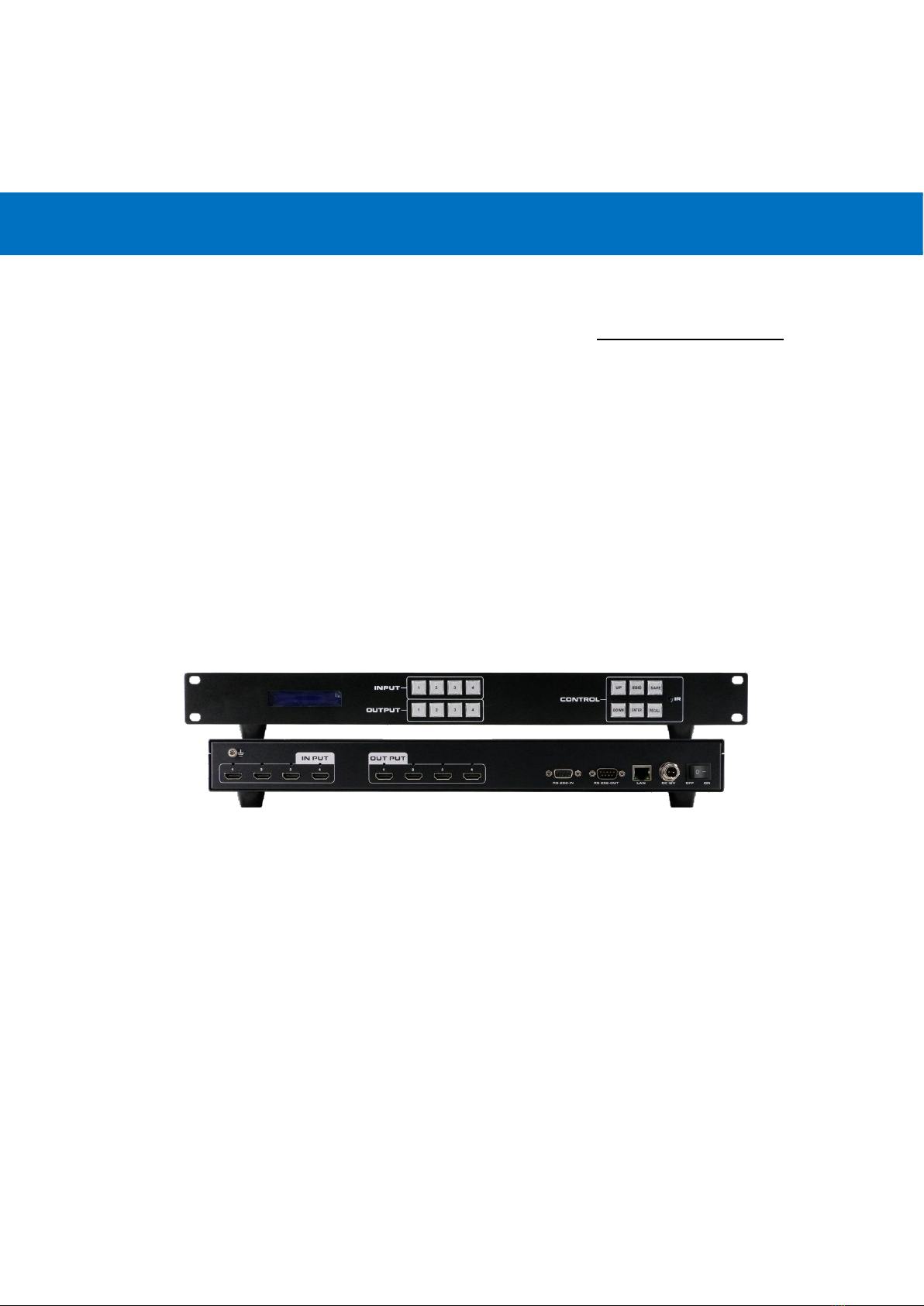
1LCD screen: for the switching, EDID, IP etc information display.
2OUTPUT: 4 HDMI output buttons
3INPUT: 4 HDMI input buttons
4CONTROL:
UP:for upward controlling
EDID:
Press it to enter EDID set mode. EDID Read:
For example,
in order to read the EDID
of output port OUT5 to input port 1, we need to press the EDID button(the indicator of
EDID lights) firstly, press the button 1 on IN side secondly, then press UP or DOWN button
to select OUT5, at the same time button 5 on OUT side lights, finally press ENTER button
(the indicator of ENTER button will flash for one time ).
SAVE: Press to save the switching status.
Down:for upward controlling
ENTER: Press to confirm to save the setting.
RECALL: Press it to recall the presets/scenes.
5IR: IR receiver for the IR remote control
6.2 Description of back panel
1For the ground wiring
2INPUT: 4 female HDMI Input ports
3OUTPUT: 4 female HDMI output ports
4RS232 IN: Female RS232 port for the R232 control
5LAN: for the IP/TCP control, the default IP address is 192.168.1.80
6DC12V: power supply port
7ON/OFF: power off/on switch
6.3 Matrix Switcher control
Matrix controller is a green software. Just copy Client.exe to PC which is used to control the
Matrix by RS232 COM port or TCP/IP.
Preparation
1. Connect PC and Matrix by RS232 cable (headers of cable should be FEMALE / MALE) or
TCP/IP (local area network).
2. Power-up Matrix.
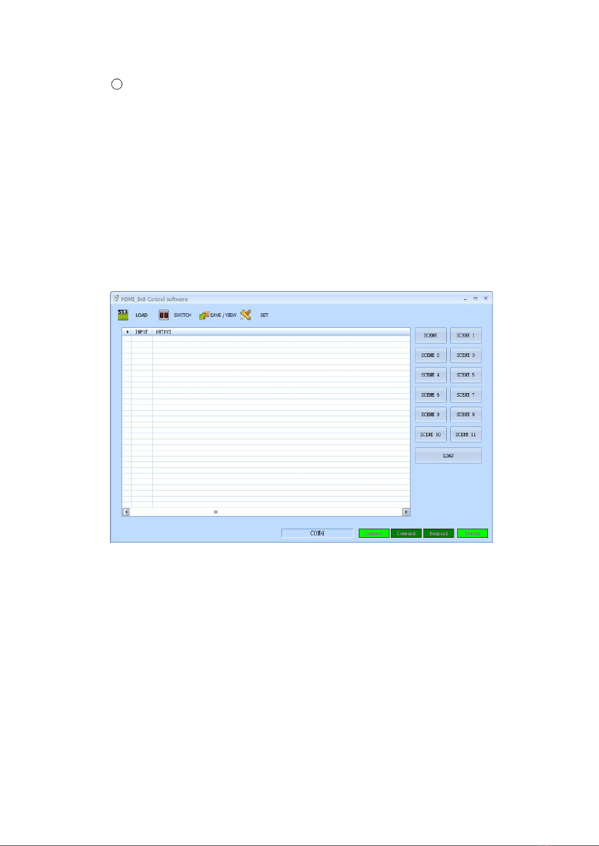
3. Double click Client.exe icon to run it. Figure 6.3-1 pops up.
Figure 6.3-1
A. Operating steps of serial port RS232 controlling matrix
Connect the computer’s RS232 port and the matrix’s RS232 port with the matched RS232
cable. Determine the port number (such as com4), click “Setup”, select “COM”and
“COM4”communication port. If the connection is correct, the right-down “STATUS”will
change to green, then you can click the “LOAD”and read the parameters of the matrix. See
figure 6.3-2.

Figure 6.3-2
B. Operating steps of LAN port controlling matrix
Select “SET ”to set up LAN port parameters. The software will search for devices
automatically. And the IP address of the device will show in the “FIND DEVICE”, see Figure
6.3-3. Double-click the IP address to fill it in.
Figure 6.3-3
Then press “LOAD”. If the connection is correct, parameters of the matrix will appear on

the interface.
Notice:It’s necessary to configure the PC’s IP when we use LAN port control mode. See
Figure 6.3-4.The default IP address of the matrix is 192.168.1.80, and the IP address of the
matrix will be shown on the front panel when powered on.
Figure 6.3-4
6.4 Operating steps of changing the name of the input/output
Click “SWITCH”to enter the switching interface. Select NO.1 input and double click it.
Figure 6.4-1 pops up. Change the name of the NO.1 input signal and then save it.
Figure 6.4-1
Click “SWITCH”to enter the switching interface. Select NO.1 output and double click it.
Figure 6.4-2 pops up. Change the name of the NO.1 output signal and then save it.

Figure 6.4-2
6.5 Switching operation of the matrix
Press “Switch”to enter the switching interface. See Figure 6.5-1. Choose input port first,
then choose the needed output port on the pop-up interface (the selected port turns
yellow). See Figure 6.5-2. Click the number again to cancel the output port, and the port
turns gray. You can choose multiple ports at a time. After all selection, press “OK”to
achieve the switching operation.

Figure 6.5-1
Figure 6.5-2
The INPUT 1 can be switched to OUTPUT 1, 2, 3, 4, 5, 6 by operating as Figure 6.5-1 and
Figure 6.5-2.
6.6 Operating steps of saving scene
Click “SAVE/VIEW”to enter “SAVE/VIEW”interface. See Figure 6.6-1.Press “Previous”
to check the current configuration of the matrix. Choose “Scene1”, press “SAVE”, then
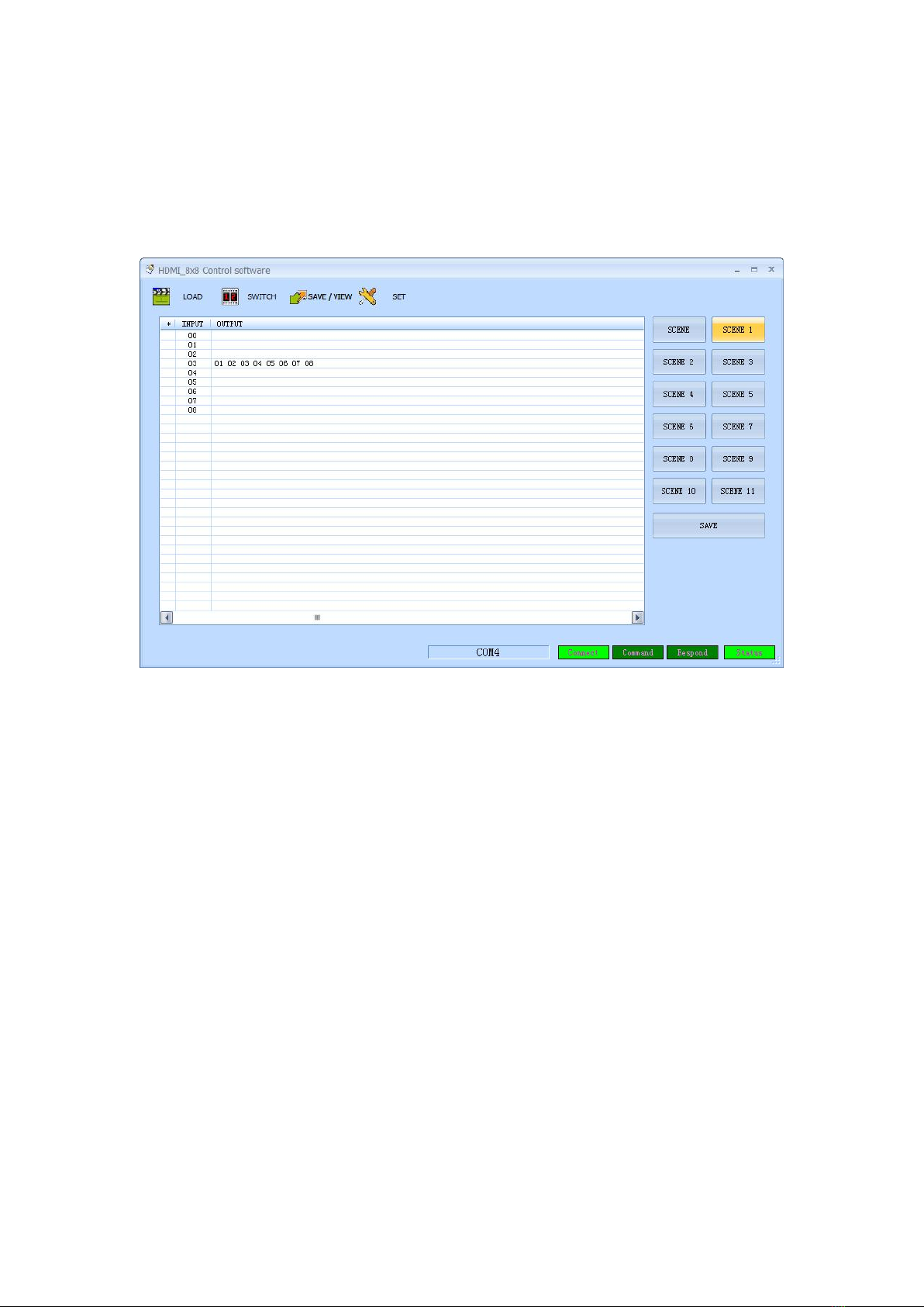
we can save the current scene to“Scene1”permanently. If“Scene1”already saved scene
before, press “Scene1”, then we can view it.
Notice:Scenes saved in “Scene 0”are current configuration, it changes according to the
matrix’s configuration.
Figure 6.6-1
6.7 Operating steps of recalling scene
Click “LOAD”to enter “LOAD”interface. See Figure 6.7-1.Choose
“Scene 1”
and press
“LOAD”to recall the scene saved in “Scene 1”.

Figure 6.7-1
6.8 Operating of EDID switching
Press “SWITCH”to enter switching interface,
choose the needed channel(during 1-8),
enter
“EDID”by right-clicking. See Figure 6.8-1.
Figure 6.8-1
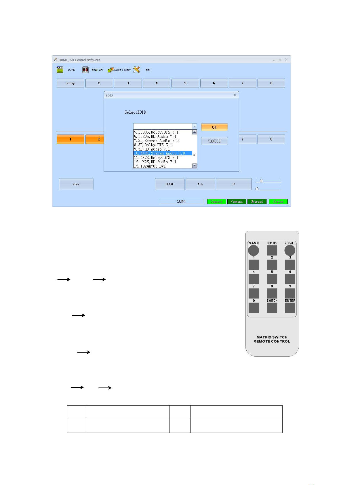
Select needed EDID parameters, click OK. See Figure 6.8-2.
Figure 6.8-2
6.9 Remote Control
Users also can control this matrix switcher with the remote control.
Channel switching:
Press the input from number “1~8”, then press “SWITCH”, then press the
output from number“1~8”, can press the outputs continually.
Eg. Switch input 1 to output 1, 2, 3:
1 SWITCH 1, 2, 3
Scene Save:
Press “SAVE”, then press the scene number from “1~8”.
Eg, Save switching input 1 to output 1,2,3 to scene 2:
"SAVE" “2”
Scene Recall :
Press “RECALL”, then press the scene number from “1~8”.
Eg, Recall scene 2:
"RECALL" “2”
EDID Setting:
Press “EDID” button to enter EDID setting mode, then press number “0” to choose the needed
EDID, then press “ENTER” to confirm, or press number “9” to cancel or return to home page.
"EDID" “0” “ENTER”
6.10 EDID mode table
NO.
EDID description
NO.
EDID description
1
OUT1(OUTPUT PORT 1)
5
1080p, Dolby. DTS 5.1

2
OUT2(OUTPUT PORT 2)
6
1080p, HD Audio 7.1
3
OUT3(OUTPUT PORT 3)
7
3D,Stereo Audio 2.0
4
OUT4(OUTPUT PORT 4)
8
3D, Dolby. DTS 5.1
5
OUT5(OUTPUT PORT 5)
9
3D, HD Audio 7.1
6
OUT6(OUTPUT PORT 6)
10
4k*2k, Stereo Audio 2.0
7
OUT7(OUTPUT PORT 7)
11
4k*2k, Dolby. DTS 5.1
8
OUT8(OUTPUT PORT 8)
12
4k*2k, HD Audio 7.1
1
1080i,Stereo Audio 2.0
13
1024x768 DVI
2
1080i, DOLBY/DTS 5.1
14
1920X1080 DVI
3
1080i, HD Audio 7.1
15
1920X1200 DVI
4
1080p, Stereo AUDIO 2.0
6.11 Control command
LAN
IP address: 192.168.1.80 (default IP)
Protocol: UDP
Port: 4000
Command: send as hex
control instruction
Functional description
EB 90 0C 00 00 80 0B 02 (x-1) (y+7) 00 00
Switch [x] input to [y] output
EB 90 0C 00 00 80 09 02 (0X) 00 00 00
Save current scene to [X], [X] means
number keys from 1 to 9
EB 90 0C 00 00 80 08 02 00 (0Y) 00 00
Load the input/output switching saved in
[Y], [Y] means number keys from 1 to 9
For example, input 1 Switch output 6, send: EB 90 0C 00 00 80 0B 02 00 0D 00 00
(1-1)=0, Hex is 00, (6+7) =13, Hex is 0D.
If input 1 Switch output 6, 7, 8, send EB 90 0C 00 00 80 0B 04 00 0D 0E 0F 00 00
04 00 0D 0E 0F means: 04 there are 4 port for switching (1 input and 3 outputs), the first one 00
is the input port, the remaining 0D 0E 0F are the output ports.
EB 90 0C 00 00 80 09 02 02 00 00 00, save the previous scene to the 02;
EB 90 0C 00 00 80 08 02 00 02 00 00, load 02 scene;
EB 90 0C 00 00 80 0B 02 01 0A 00 00
RS232
Baud rate: 9600, N, 8, 1
Use RS232 direct cable
control instruction
Functional description

[x] X [y].
Switch [x] input to [y] output
Save [X].
Save current scene to [X], [X] means
number keys from 1 to 9
Recall [Y].
Load the input/output switching saved in
[Y], [Y] means number keys from 1 to 9
Buzzer on.
Turn on the beep sound
Buzzer off.
Turn off the beep sound
7. Common Problem Shooting
Q: Serial port operation is out of order, can not control to switch?
A: The serial port is damaged or not started
Solution: Make sure the port uses direct serial port line, check the connection of PC software
serial port.
Power failure: Check the power fuses and connecting lines;
Signal interference: Make sure the cables and plugs are connected well, the cables meet the
requirements, the system is ground connected well, the AC power between devices have the
same grounding system;
Accidental damage:Sent back to the manufacturer for recondition.
8. After-Sales
8.1 Warranty Information
The Company warrants that the process and materials of the product are not defective under
normal use and service for 2 (2) years following the date of purchase from the Company or its
authorized distributors.
If the product does not work within the guaranteed warranty period, the company will choose
and pay for the repair of the defective product or component, the delivery of the equivalent
product or component to the user for replacement of the defective item, or refund the
payment which users have made.
The replaced product will become the property of the Company.
The replacement product could be new or repaired.
Whichever is longer, any replacement or repaired of the product or component is for a period
of ninety (90) days or the remaining period of the initial warranty. The Company shall not be

responsible for any software, firmware, information, or memory data contained in, stored in,
or integrated with the product repaired by the customer's return, whether or not during the
warranty period.
8.2 Warranty limitations and exceptions
Except above limited warranty, if the product is damaged by over usage, incorrectly use, ignore,
accident, unusual physical pressure or voltage, unauthorized modification, alteration or
services rendered by someone other than the Company or its authorized agent, the company
will not have to bear additional obligations. Except using the product properly in the proper
application or normal usage
9. Version Information
Description of version(Document number:DOC-*FIX-MANAGER-400-E)
Date
Version number
Description
Feb 2019
V1.01.01
First version
This manual suits for next models
1
Table of contents
Other BeingHD Matrix Switcher manuals


Popular Matrix Switcher manuals by other brands

Rose electronics
Rose electronics UltraMatrix AV Installation and operation manual

RME Audio
RME Audio MADI Converter user guide

Extron electronics
Extron electronics 64 Series Specifications

Shinybow USA
Shinybow USA SB-4184 instruction manual

CYP
CYP PUV-662PL-4K22 Operation manual

Binary
Binary B-120-HDMATRIX-4x4 Configuration utility manual


