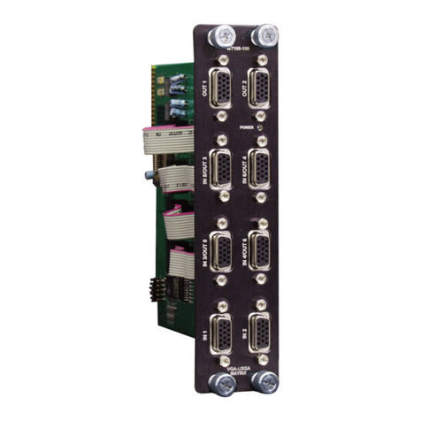
MULTI-TASKER™
7
INSTALLING YOUR MT107-202 6
Step 1. Locate the MT107-103 currently installed
in the Multi-Tasker™. Ensure there are
enough empty slots in the enclosure to
allow for the one or more MT107-202's to
be installed.
Step 2. Route the ribbon cables through the notch
in the add-on boards and connect to the
MT107-103 base assembly using special
cables provided with the Engine. Make
sure that cable connector is secured in
the socket of the input card.
Step 3. Carefully, slide the MT107-202 into an
empty slot in the Multi-Tasker™
Enclosure.
Step 4. Secure each card by tightening the
retainer screws at the top and bottom of
each card.
OPERATION 7
7.1 RS-232 CONTROL
The MT107-202 has many advanced remote
control capabilities when used in the
Multi-Tasker™ Enclosure as part of an
MT107-103 Matrix Switcher. These capabilities
are accessible through standard RS-232
communication. The actual controlling can be
accomplished through a computer control
system or any other device capable of sending
RS-232 commands.
7.2 DESCRIPTION OF COMMANDS
Please, see the MT107-103 User's Guide for a
full listing of commands available for the
MT107-202 as part of a Multi-Tasker™ Matrix
Switcher.
TROUBLESHOOTING GUIDE 8
We have carefully tested and have found no
problems in the supplied MT107-202. However, we
would like to offer suggestions for the following:
8.1 NO SOUND
Cause 1: The source has a problem.
Solution: Check the source and make sure
that there is a signal present and all
source connections are correct. If
the source is working and there is
still no sound, see Cause 2.
Cause 2: The input signal is not detected.
Solution 1: In MTSetup™, or other control
software, send the [SDI] command.
This command is detailed in the
MT107-103's User Guide. Verify a
signal is detected for the input
number in question. If a signal is not
detected, see Solution 2.
Solution 2: Verify the MT107-202 is connected
to the MT107-103 and that the cable
is in good condition. If a signal is
detected, see Cause 3. If there is no
signal detected, please, call Altinex
at (714) 990-2300.
Cause 3: The path is not selected.
Solution: Make sure the input to output path is
correctly selected.
For example, Input 17 is connected
to Output 1 in the matrix engine.
Physically, the source signal is
connected to Input 17 and the
receiving device cable is connected
to Output 1. See RS-232 accessible
commands in Section 7 of the
MT107-103's User Guide for
command details.
If no sound is present, see Cause 4.
