2USA
•Only connect the dshwasher to the
power supply when all nstallaton and
plumbng work s complete.
•If the dshwasher s nstalled n a
locaton that experences freezng
temperatures (e.g. n a vacaton home,
cabn, etc.), you must dran all the
water from the dshwasher’s nteror.
Water system ruptures that occur as
a result of freezng are not covered by
warranty.
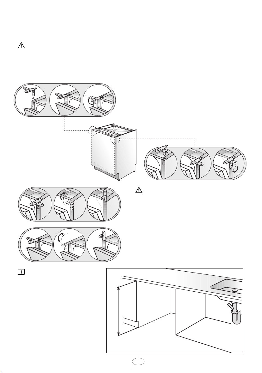
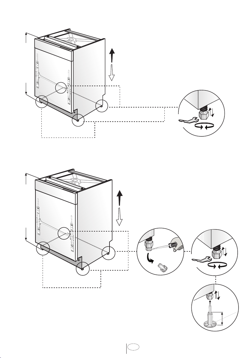
•Dshwasher must be secured to
adjacent cabnetry usng the brackets
provded. Falure to do ths may cause
damage to property or bodly njury.
•Connect to a properly rated, protected
and szed power supply crcut to avod
electrcal overload. The dshwasher
s desgned for an electrcal supply
of 120 V (volts), 60 Hz (hertz), AC,
connected to a dshwasher-dedcated,
properly grounded electrcal crcut
wth a fuse or breakers rated for 15
amperes. Electrcal supply conductors
shall be a mnmum of # 16 AWG
copper wre rated at 75 °C (167 °F) or
hgher. These requrements must be
met to prevent njury and machne
damage. Consult a qualfed electrcan
f n doubt.
•Do not use any extenson cord or
portable outlet devce to connect the
dshwasher to a power supply.
•Ensure that any plastc wrappngs,
bags, small peces etc. are dsposed
of safely and kept out of the reach of
chldren. Danger of suffocaton!
•Remove the door to the washng
compartment when removng an old
dshwasher from servce or dscardng
t. Ensure that the applance presents
no danger to chldren whle beng
stored for dsposal.
•Old applances may contan materals
that can be recycled. Please contact
your local recyclng authorty about
the possblty of recyclng these
materals.
NOTICE :
•The dshwasher dran hose must be
nstalled wth a dran loop at least
28” (710mm) off the cabnet floor;
otherwse the dshwasher may not
dran properly.
•Ths dshwasher s ntended for
resdental use only, and should not be
used n commercal establshments.
•New nstallaton - If the dshwasher s
a new nstallaton, most of the work
must be done before the dshwasher
s moved nto place.
•Replacement - If the dshwasher s
replacng another dshwasher, check
the exstng dshwasher connectons
for compatblty wth the new
dshwasher, and replace parts as
necessary.
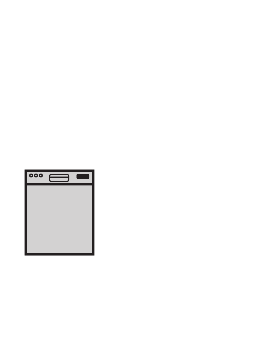
1.1 INSPECT THE DISHWASHER
After unpackng the dshwasher and pror
to nstallaton, thoroughly nspect the
dshwasher for possble freght or cosmetc
damage. Report any damage mmedately.
NOTICE :
•Cosmetc defects must be reported
wthn 10 days of nstallaton.
•Do not dscard any bags or tems that
come wth the orgnal package untl
after the entre nstallaton has been
completed.