Pictograms and symbols
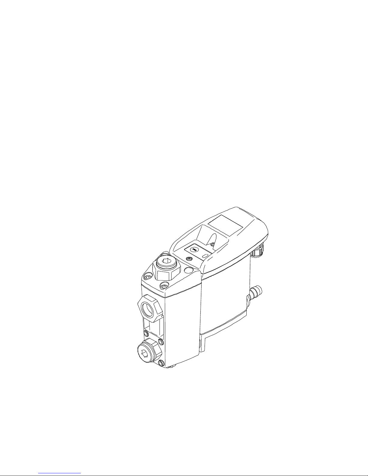
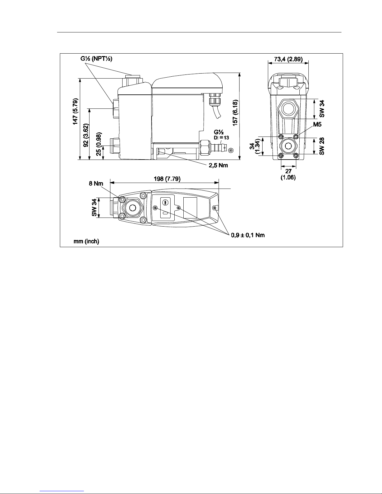
4 BEKOMAT® 33U / 33U CO
Pos: 1 /Beko Technische Dokume ntat ion/Überschriften/ 1/Piktogr amme und Symbole @ 1\ mod_1290773595840_ 2901.docx @ 20524 @ 1 @ 1
1Pictograms and symbols
Pos: 2 / Beko TechnischeDokume ntat ion/Pikt ogramme/ Anleitung beachten blau @ 0\ mod_12132 683002 55_2901. docx @ 8336 @ @ 1
Observe the installation and operating instructions
Pos: 3 /Beko Technische Dokume ntat ion/Piktogramm e/Anle itung beachten s/w Typenschild@ 1\m od_12907 7218014 2_2901.docx @ 20491 @ @ 1
Observe the installation and operating instructions
(on the type plate)
Pos: 4 /Beko Technische Dokume nt at ion/Pikt ogr amm e/ G efahr War nung Vorsicht s/ w @ 0\ m od_121326568517 4_2901.docx @ 8260 @ @ 1
General danger symbol (danger, warning, caution)
Pos: 5 /Beko Technische Dokume nt at ion/Pikt ogr amm e/ G +W+V Netzspannung s/w @ 0\m od_121326619370 1_2901.docx @ 8298 @ @ 1
General danger symbol (danger, warning, caution) for supply voltage and supply voltage-carry-
ing plant components
Pos: 6 /Beko Technische Dokume nt at ion/Überschrift en/ 1/ Sicherhe itshin weise @ 0\m od_118363760926 1_2901.docx @ 5367@ 1 @ 1
2 Safety instructions
Pos: 7 /Beko Technische Dokume ntat ion/G lobale Text e/A llgeme iner Hin weis BM @ 0\ mod_118361573731 3_2901.docx @ 4006 @ @ 1
Pos: 8 /Beko Technische Dokume ntat ion/Sicherhe it/HinweisAn le itung BEKO (männl. Name) @ 0\ mod_1184147787557_2901.docx @ 5760@ @ 1
Please check whether or not these instructions correspond to the device type.
Adhere to all advice given in these operating instructions. They include essential information
which must be observed during the installation, operation and maintenance. Therefore it is im-
perative for the service technician and the responsible operator / technical staff to read these
operating instructions prior to installation, start-up and maintenance.
The operating instructions must be accessible at any time at the place of application of the
BEKOMAT®33U / 33U CO .
In addition to these operating instructions, local or national regulations must be complied with,
if necessary.
Make sure that the BEKOMAT®33U / 33U CO is operated only within the permissible limit val-
ues indicated on the type plate. Any deviation involves a risk for persons and materials, and
may result in malfunction and service failures.
If you have any queries regarding these installation- and operating instructions, please contact
BEKO TECHNOLOGIES GMBH.
Pos: 9 /Beko Technische Dokume nt at ion/Sicher he it/ G ef ahr Druckluft @ 0\ m od_118414814385 4_2901.docx @ 5778@ @ 1
Danger!
Compressed air!
Risk of serious injury or death through contact with quickly or suddenly escaping com-
pressed air or through bursting plant components or plant components which are not
secured.
Pos: 10 /Beko Technische Dok um entat ion/Sich er heit/M aßnahmen Druckl uft BM @ 0\m od_1184148284291_290 1. docx @ 5814@ @ 1
Measures:
• Do not exceed the maximum operating pressure (see type plate).
• Only carry out service measures when the system is pressureless.
•Use pressure-resistant installation material only.
• The feed pipe must be tubed firmly. Discharge pipe: short, fixed pressure hose onto pressure-resistant
pipe.
• Make sure that persons or objects cannot be hit by condensate or escaping compressed air.
Pos: 11 /Beko Technische Dok um entat ion/Sich er heit/G ef ahr Net zspannung 1 s/w @ 0\m od_1184148186948 _2901.docx @ 5796@ @ 1