BEL MTM-1A User manual

1
METALLOGRAPHIC MICROSCOPE
mod. MTM-1A
USER MANUAL
F i l e n a m e : M T M - 1 A . d o c

2
INSTALLATION OF MICROSCOPE
Take out the field diaphragm adjustment screw from the
package and plug each correspond of the hole
Field diaphragm adjustment screw

3
The reflected light metallurgical MTM-1
、
MTM-1A
microscope is suitable to observe the microscopical surfaces of
non-transparent object. It is equipped with large move range stage、
vertical illumination, plan achromatic objectives and wide-field
eyepieces. It provides clear and high-contrast picture, and with polarizer
device. It is the ideal instrument in research work in metallography,
mineralogy, precision engineering, electronics etc. It’s suitable for
scientific research, teaching demonstration in the colleges and factory.
NOTE:
Stage cross travel range: longitudinal 153 mm traverse153 mm. for MTM-1
Stage cross travel range: longitudinal 203 mm traverse 203 mm. for MTM-1A
Ⅰ、SPECIFICATIONS
1.Eyepieces
Type
Magnification
Focus(mm)
Field(mm)
Remark
Wide field
eyepiece
10X
25
φ18
16X
15.6
φ11
Optional
Plan Dividing
10X
25
φ18
Optional
2.Objectives
Type
Magnification
N.A
W.D(mm)
Remark
Plan
Achromatic
(no cover
glass)
5X
0.12
18.3
10X
0.25
8.9
20X
0.40
8.7
40X
0.65
3.7
50X
0.70
2.02
Optional
80X
0.80
0.96
3.Total Magnification
5X
10X
20X
40X
50X
80X
10X
50X
100X
200X
400X
500X
800X
16X
80X
160X
320X
640X
800X
1280X
Objectives
Total
Magnification
Eyepieces

4
4. Vertical illuminator
(1) With light source of 6V/20W halogen lamp and the brightness can be
adjusted;
(2) Power supply: can be operated on AC 220V 50HZ or AC 110V
60HZ;
(3) Turned filter group: yellow、blue、green、ground glass;
(4) With polarizer;
5. Stage cross travel range:
longitudinal 153 mm traverse 153 mm for MTM-1;
longitudinal 203 mm traverse 203 mm for MTM-1A;
6. Fine focusing knob: minimum division 0.0008mm;
7. Interpupillary distance adjustment range: from 53mmto 75mm;
8. Anti-fungus: Yes.

5
Ⅱ、COMPONENTS
1.Filter seat 2.Field diaphragm adjustment screw 3.Polarization
adjustment pole 4.Trinocular 5.Observation/photo lever 6.Polarizer
lever 7.Objective 8.Stage 9.Limit holding knob 10.Coarse focusing
knob 11.Fine focusing knob 12.pole
1
2
3
4
5
6
7
8
9
10
11
12
Fig.1

6
1.Eyepiece 2.Field diaphragm adjustment lever 3.Lamp holding screw
4.Condenser adjustment lever 5.Field diaphragm adjustment screw
6.Aperture diaphragm adjustment lever 7.Power supply plug
8.Electrical outlet 9.Light control 10.Power switch 11.Cross knob
12.Lengthwise knob 13.Adjustable tensional knob 14.Binocular
locking screw
Anti-fungus installed
7
8
1
2
3
4
5
6
9
10
11
12
13
14
Fig.2

7
Ⅲ、OBSERVING OPERATION
1. Press the power switch 10 on the side “I”, which means the circuits
is got through.(Fig.2)
2. Push the observation/photo lever 5 in the trinocular tube to
observation position. (Fig.3)
3. Interchange the objective 10X into optical path, with 10X eyepiece
to observe, turn the coarse/fine adjustment knob 5/6 to make the
image clear, pull the field diaphragm adjustment lever 4 to let the
diaphragm smaller, then adjust the field diaphragm adjustment
screw 1 to make the center of the field diaphragm on the optical
center. Pull the diaphragm lever 4 again to let the image of the
diaphragm slightly larger than diaphragm in the field (Fig.3),
Now it’s ready to use.
4. This microscope is equipped with simple polarization device. Push
the Polarizer lever 3 to make the analyzer into the optical path of
the observation. Push the polarizer 2 into the vertical illuminator
(Fig.3), Rotate the polarizer 2 while watching the brightness in the
field and let the polarizer and analyzer orthogonally, then put the
specimen on the stage and observe with orthogonal polarization
condition.
1. Field diaphragm adjustment screw 2. Polarization adjustment pole
3. Polarizer lever 4. Field diaphragm adjustment lever
5.Observation/photo lever 6. Fine focusing knob 7. Coarse focusing
knob
1
2
3
4
6
7
Fig.3
5

8
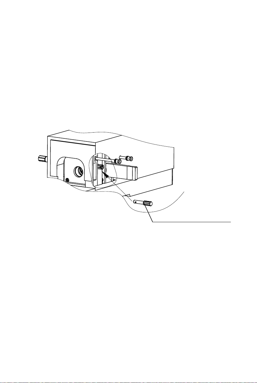
5. Adjustment of interpupillary distance
Put the specimen on the stage and focus to make the image of specimen
clear. Adjust the interpupillary distance of binocular until the right-left
field of view can be composed one (Fig.4).
6. Adjustment of diopter
Turn the 40X objective to working position.
Firstly, observe the right tube with right eye,
adjust coarse-fine focusing knob to make the
image clearly. Secondly, observe the left tube
with left eye, adjust the diopter control 1 to
make the image clearly (Fig.4).
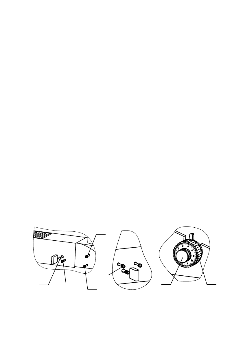
7. Coarse/Fine focusing
The instrument used coaxial coarse/fine focusing mechanism. The
adjustable tensional knob 4 used for adjusting the tension of the coarse
focusing knob 3 to prevent the stage from naturally sliding down. The
limit knob 1 prevents accidental specimen/ objective contact. 2 is fine
focusing knob.(Fig.5)
8. Movement of stage (Fig.5)
The pole 5 could be quickly move the stage, or use the Cross knob
7 and Lengthwise knob 6 to adjust.
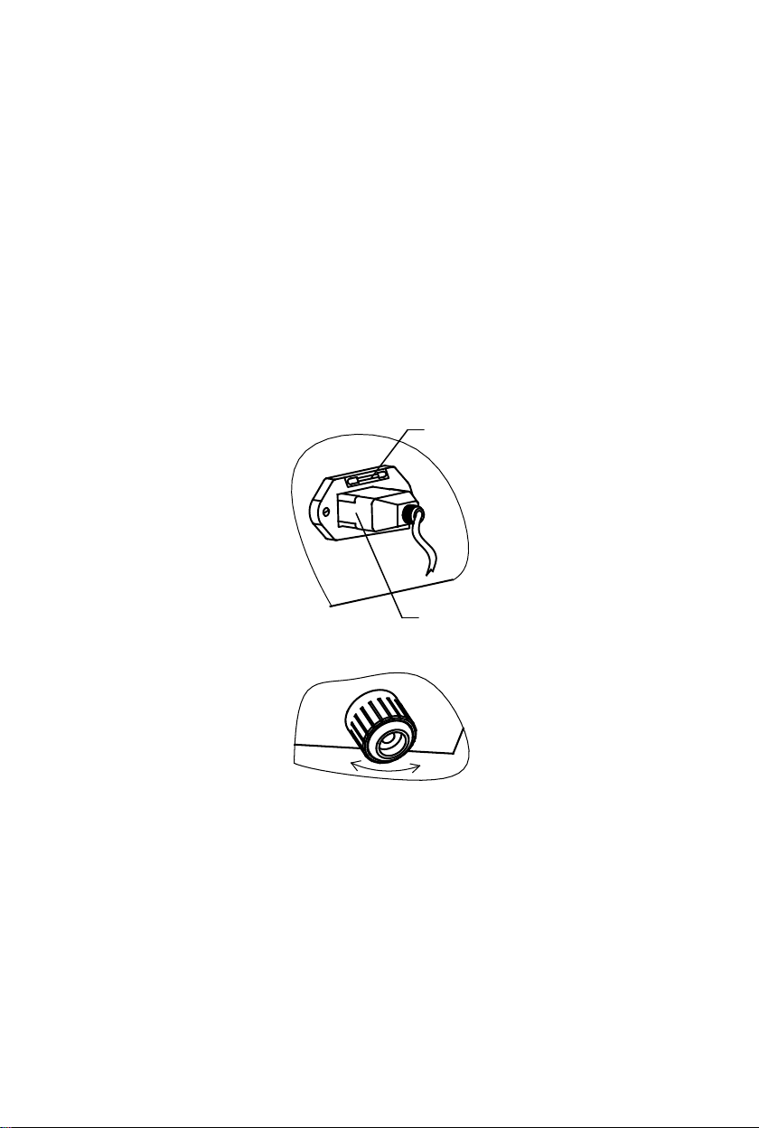
9. Illumination Adjustment(Fig.6)
A. Take away the 10X objective, from the nosepiece turn the
nosepiece to its anchor point;
B. Put a piece of white paper on the stage;
1
Fig.4
Fig.5
2
3
4
6
7
5
1

9
C. Loosen the locking screw and move the location screw forward or
backward to make the image of filament be in the center of paper;
D. If the image of filament not clear, you should adjust the condenser
adjusting handle to make the image clear;
E. If the image of filament offset the center of stage too far, you
should adjust the screw 3 and push it to side a little;
F. Install the 10X objective and put a piece of specimen on the stage
again;
G. Adjust the coarse/fine focusing knob to make the image of
specimen clear;
H. If brightness of field not equality, you can adjust the screw 3 or
move the lamp 2 slightly to make the brightness of field equality;
I. Turn the field diaphragm to minimum, adjust the field diaphragm
adjusting screw to make the center of field diaphragm and field be
superposition, then turn the field diaphragm until you can not see the
image of field diaphragm in the field;(Fig.2)
J. When use other magnification objective, you can adjust the aperture
diaphragm and the brightness of illumination to obtain satisfactory
contrast;
K. In order to obtain an image of good quality, you can use a piece of
brush glass or filters according to your need.
Luminous
hole
Filament
image
Fig.6
1
2
3
4
5

10
10. Exchange the lamp (Fig.6)
A. Switch off the power supply and pull out the plug of electrical wire;
B. Use tool open the screw 4, take off the cover 5;
C. Put out the old lamp 2, and insert a new lamp 2; Clean the lamp
with alcohol;
D. Adjust the lamp according to the“OBSERVING OPERATION 9”.
11. Exchange the fuse(Fig.7)
Pull out power supply plug 2 from socket, take out socket of fuse 1.
Changing the fuse. Install socket of fuse and plug again.
The specification of fuse:
Ф
5, 0.5A
If stage dosen't balance, you can adjust the adjustment nut
of chassis
Ⅳ、MAINTENANCE
1. Sweep the lens
Sweep the lens by lens tissue or soft fabric immersed with mixed
liquid of alcohol/ether or diethyl benzene. Cleaning the oil on the 100X
objective whenever finish operating.
2.Clean the painted parts
The dust on the painted parts can be removed by gauze, for the
grease spots, the gauze immersed slightly with aviation gasoline is
Fig.7
1
2

11
recommended. Do not use organic solvents such as alcohol, ether or
other thinner etc, for cleaning the pointed parts or plastic components.
3. Avoid disassembling the microscope
Being a precise instrument, do not disassemble the microscope
casually that may cause serious damage to its performance.
4. Being not used
Cover the microscope with polymethyl methacrylate or
polyethylene and places where there is dry and modules. Suggest that
storage all objectives and eyepieces in closed container with drying
agent.

12
Ⅴ
、
PROBLEM AND SOLUTION
TYPE OF PROBLEM
PROBLEM
SOLUTION
A.Lamp no light
1
Check the socket
and plug whether
connect well
Connect well
2
Check the lamp
whether broken
exchange the same
specification lamp
3
Pull out the power
plug and check the
fuse whether
broken
exchange the same
specification fuse
B.Illumination light
not equality
See the instruction
“Ⅲ.OBSERVING
OPERATION 9”to adjust
C.Something estop
the field
1
Check the
trinocular pole
whether push to
the locate point
push to the locate point
2
Check the filter
seat whether locate
well
put the filter seat good
location
D.Can not see the
image while
adjusting coarse/fine
focusing
See the instruction
“Ⅳ.OBSERVING
OPERATION 7”to adjust
E.Automatic offset
the focus
See the instruction
“Ⅳ.OBSERVING
OPERATION 7”to adjust
F.The image no
clear on the focus
plane
Check the eyepiece or
objective surface
whether dirty
Solve according to the
instruction
“Ⅴ.MAINTENANCE”; If
the lens has been damaged,
please send it to us for
repairs or buy a new one.

13
CONFORMITY DECLARATION
We, Bel Engineering s.r.l. Via Carlo Carrà 5, Monza (MB), declare under our
exclusive responsability that the Microscope models
MTM-1A
this declaration refers to, are in compliance with the following rules:
EMC std.:
EN 61326-1 (2006)
EN 61000-3-2 (2006)
EN 61000-3-3 (1995) + A1 (2001) + A2 (2005)
Harmonized by the directive 2004/108/EC
SAFETY std.:
EN 61010-1 (2001)
Harmonized by the directive 2006/95/EC
Table of contents
Other BEL Microscope manuals