Belden Grass valley EC 2-100 User manual

User’s Guide
13-00095-000
2021-03-11
EC 2-100
2-INCH OCULAR VIEWFINDER FOR LDX 100 SERIES

ii
Notices
FCC Compliance
This product generates, uses, and can radiate radio frequency energy and if not installed
and used in accordance with the instructions, may cause interference to radio
communications. It has been tested and found to comply with the limits for a class A digital
device pursuant to part 15 of the FCC rules, which are designed to provide reasonable
protection against such interference when operated in a commercial environment.
Operation of this product in a residential area is likely to cause interference in which case
the user at his own expense will be required to take whatever measures may be required to
correct the interference.
Patent Information
This product may be protected by one or more patents. For further information, please visit:
www.grassvalley.com/patents/
Copyright and Trademark Notice
Copyright © 2020, Grass Valley Canada. All rights reserved.
Grass Valley, EC 2-100 are trademarks or registered trademarks of Grass Valley Canada.
Grass Valley Canada, and other parties may also have trademark rights in other terms used
herein.
Terms and Conditions
Please read the following terms and conditions carefully. By using Broadcast Equipment
documentation, you agree to the following terms and conditions.
Grass Valley hereby grants permission and license to owners of Broadcast Equipment to use
their product manuals for their own internal business use. Manuals for Grass Valley
products may not be reproduced or transmitted in any form or by any means, electronic or
mechanical, including photocopying and recording, for any purpose unless specifically
authorized in writing by Grass Valley.
A Grass Valley manual may have been revised to reflect changes made to the product
during its manufacturing life. Thus, different versions of a manual may exist for any given
product. Care should be taken to ensure that one obtains the proper manual version for a
specific product serial number.
Information in this document is subject to change without notice and does not represent a
commitment on the part of Grass Valley.
Warranty information is available from the Legal Terms and Conditions section of Grass
Valley’s website (www.grassvalley.com).
Title EC 2-100 User’s Guide
Part Number 13-00095-000
Revision 2021-03-11, 11:07

iii
EC 2-100
User’s Guide
Cautions for LCD and TFT Displays
Excessive usage may harm your vision. Rest for 10 minutes for every 30 minutes of
usage.
If the LCD or TFT glass is broken, handle glass fragments with care when disposing
of them. If any fluid leaks out of a damaged glass cell, be careful not to get the liquid crystal
fluid in your mouth or skin. If the liquid crystal touches your skin or clothes, wash it off
immediately using soap and water. Never swallow the fluid. The toxicity is extremely low
but caution should be exercised at all times.
Environmental Information
European (CE) WEEE directive.
This symbol on the product(s) means that at the end of life disposal it should not be mixed
with general waste.
Visit www.grassvalley.com for recycling information.
Grass Valley believes this environmental information to be correct but cannot guarantee its
completeness or accuracy since it is based on data received from sources outside our
company. All specifications are subject to change without notice.
If you have questions about Grass Valley environmental and social involvement (WEEE,
RoHS, REACH, etc.), please contact us at environment@grassvalley.com.
Safety and EMC Standards
This equipment complies with the following standards:
Safety Standards

iv
Notices
Information Technology Equipment - Safety Part 1
IEC62368-1:2018
Safety of Information Technology Equipment Including Electrical Business Equipment.
EMC Standards
This unit conforms to the following standards:
EN55032:2012 + C2:2013 (Class A)
Electromagnetic Compatibility of multimedia equipment - Emission requirements
EN55103-2:2009 (Environment E2)
Electromagnetic Compatibility, Product family standard for audio, video, audio-visual and
entertainment lighting control apparatus for professional use. Part 2. Immunity
FCC / CFR 47:Part 15 (Class A)
WARNING
This equipment is compliant with Class A of CISPR 32. In a residential environment this
equipment may cause radio interference.
Federal Communications Commission Rules Part 15, Subpart B
Caution to the user that changes or modifications not expressly approved by the party
responsible for compliance could void the user's authority to operate the equipment.
following the provisions of:
• the Low Voltage directive 2014/35/EU
• the EMC directive 2014/30/EU
☞Note
☞Note
This equipment has been tested and found to comply with the limits for a Class A digital
device, pursuant to part 15 of the FCC Rules. These limits are designed to provide
reasonable protection against harmful interference when the equipment is operated in a
commercial environment.
This equipment generates, uses, and can radiate radio frequency energy and, if not
installed and used in accordance with the instruction manual, may cause harmful
interference to radio communications.
Operation of this equipment in a residential area is likely to cause harmful interference in
which case the user will be required to correct the interference at his own expense.

v
Table of Contents
1Introduction . . . . . . . . . . . . . . . . . . . . . . . . . . . . . . . . . . . . . . . . . . . 1
Overview. . . . . . . . . . . . . . . . . . . . . . . . . . . . . . . . . . . . . . . . . . . . . . . . . . . . . . . . . . . . . . . . . . . . . . . . . . 1
Key features. . . . . . . . . . . . . . . . . . . . . . . . . . . . . . . . . . . . . . . . . . . . . . . . . . . . . . . . . . . . . . . . . . . 1
2Installation. . . . . . . . . . . . . . . . . . . . . . . . . . . . . . . . . . . . . . . . . . . . . 3
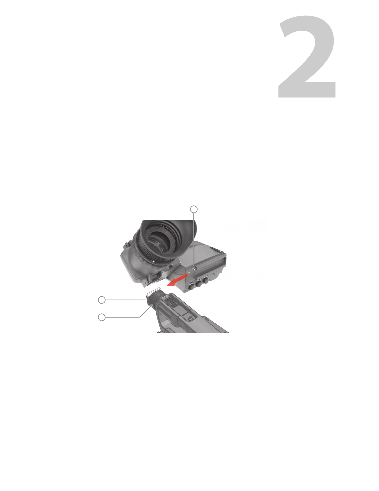
Mounting the viewfinder . . . . . . . . . . . . . . . . . . . . . . . . . . . . . . . . . . . . . . . . . . . . . . . . . . . . . . . . . . 3
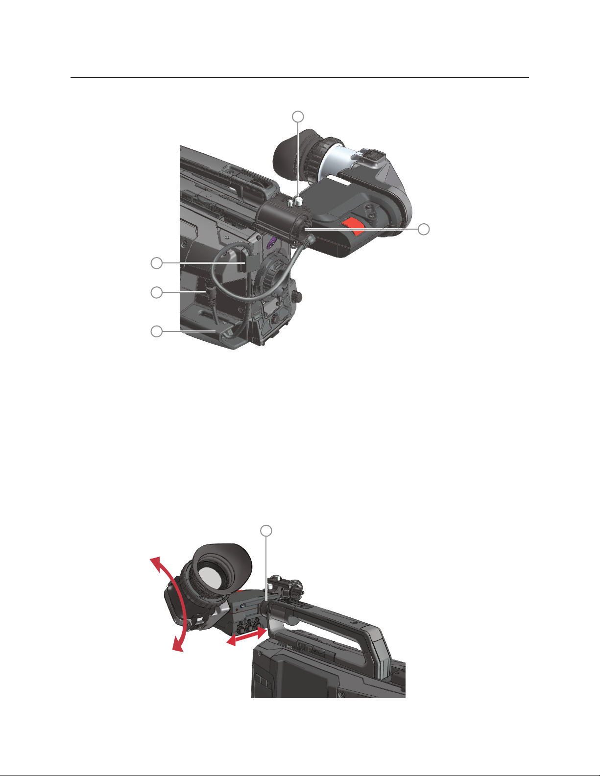
Positioning the viewfinder . . . . . . . . . . . . . . . . . . . . . . . . . . . . . . . . . . . . . . . . . . . . . . . . . . . . . . . . . 4
Horizontal. . . . . . . . . . . . . . . . . . . . . . . . . . . . . . . . . . . . . . . . . . . . . . . . . . . . . . . . . . . . . . . . . . . . . 4
Angular . . . . . . . . . . . . . . . . . . . . . . . . . . . . . . . . . . . . . . . . . . . . . . . . . . . . . . . . . . . . . . . . . . . . . . . 5
Lateral . . . . . . . . . . . . . . . . . . . . . . . . . . . . . . . . . . . . . . . . . . . . . . . . . . . . . . . . . . . . . . . . . . . . . . . . 5
Distance viewing . . . . . . . . . . . . . . . . . . . . . . . . . . . . . . . . . . . . . . . . . . . . . . . . . . . . . . . . . . . . . . . . . . 5
3Operation. . . . . . . . . . . . . . . . . . . . . . . . . . . . . . . . . . . . . . . . . . . . . . 7
Controls. . . . . . . . . . . . . . . . . . . . . . . . . . . . . . . . . . . . . . . . . . . . . . . . . . . . . . . . . . . . . . . . . . . . . . . . . . . 7
Rear panel . . . . . . . . . . . . . . . . . . . . . . . . . . . . . . . . . . . . . . . . . . . . . . . . . . . . . . . . . . . . . . . . . . . . 7
Front panel . . . . . . . . . . . . . . . . . . . . . . . . . . . . . . . . . . . . . . . . . . . . . . . . . . . . . . . . . . . . . . . . . . . 9
Indicators . . . . . . . . . . . . . . . . . . . . . . . . . . . . . . . . . . . . . . . . . . . . . . . . . . . . . . . . . . . . . . . . . . . . . . . .10
LED indicators. . . . . . . . . . . . . . . . . . . . . . . . . . . . . . . . . . . . . . . . . . . . . . . . . . . . . . . . . . . . . . . .10
On screen indicators. . . . . . . . . . . . . . . . . . . . . . . . . . . . . . . . . . . . . . . . . . . . . . . . . . . . . . . . . .12
On screen markers . . . . . . . . . . . . . . . . . . . . . . . . . . . . . . . . . . . . . . . . . . . . . . . . . . . . . . . . . . .13
On screen (framing) boxes . . . . . . . . . . . . . . . . . . . . . . . . . . . . . . . . . . . . . . . . . . . . . . . . . . . .13
Operational functions . . . . . . . . . . . . . . . . . . . . . . . . . . . . . . . . . . . . . . . . . . . . . . . . . . . . . . . . . . . .14
Mono . . . . . . . . . . . . . . . . . . . . . . . . . . . . . . . . . . . . . . . . . . . . . . . . . . . . . . . . . . . . . . . . . . . . . . . .14
Ext1. . . . . . . . . . . . . . . . . . . . . . . . . . . . . . . . . . . . . . . . . . . . . . . . . . . . . . . . . . . . . . . . . . . . . . . . . .14
Ext2. . . . . . . . . . . . . . . . . . . . . . . . . . . . . . . . . . . . . . . . . . . . . . . . . . . . . . . . . . . . . . . . . . . . . . . . . .14
VF Zoom . . . . . . . . . . . . . . . . . . . . . . . . . . . . . . . . . . . . . . . . . . . . . . . . . . . . . . . . . . . . . . . . . . . . .14
Text. . . . . . . . . . . . . . . . . . . . . . . . . . . . . . . . . . . . . . . . . . . . . . . . . . . . . . . . . . . . . . . . . . . . . . . . . .14
Call . . . . . . . . . . . . . . . . . . . . . . . . . . . . . . . . . . . . . . . . . . . . . . . . . . . . . . . . . . . . . . . . . . . . . . . . . .14
Viewfinder detail . . . . . . . . . . . . . . . . . . . . . . . . . . . . . . . . . . . . . . . . . . . . . . . . . . . . . . . . . . . . .14
Focus Assist . . . . . . . . . . . . . . . . . . . . . . . . . . . . . . . . . . . . . . . . . . . . . . . . . . . . . . . . . . . . . . . . . .15
Zebra . . . . . . . . . . . . . . . . . . . . . . . . . . . . . . . . . . . . . . . . . . . . . . . . . . . . . . . . . . . . . . . . . . . . . . . .15
4Viewfinder setup . . . . . . . . . . . . . . . . . . . . . . . . . . . . . . . . . . . . . . 17
Menu contents . . . . . . . . . . . . . . . . . . . . . . . . . . . . . . . . . . . . . . . . . . . . . . . . . . . . . . . . . . . . . . . . . . .17
Entering the menu . . . . . . . . . . . . . . . . . . . . . . . . . . . . . . . . . . . . . . . . . . . . . . . . . . . . . . . . . . .17
Diagnostics menu (DIAG) . . . . . . . . . . . . . . . . . . . . . . . . . . . . . . . . . . . . . . . . . . . . . . . . . . . . .18
Configuration menu (CONFIG) . . . . . . . . . . . . . . . . . . . . . . . . . . . . . . . . . . . . . . . . . . . . . . . .18
Indicator adjustment submenu (INDADJ). . . . . . . . . . . . . . . . . . . . . . . . . . . . . . . . . . . . . .18
Color menu (COLOR) . . . . . . . . . . . . . . . . . . . . . . . . . . . . . . . . . . . . . . . . . . . . . . . . . . . . . . . . .19

vi
Table of Contents
Viewfinder status information. . . . . . . . . . . . . . . . . . . . . . . . . . . . . . . . . . . . . . . . . . . . . . . . . . . . .19
Appendix A Specifications . . . . . . . . . . . . . . . . . . . . . . . . . . . . . . . . 21
General . . . . . . . . . . . . . . . . . . . . . . . . . . . . . . . . . . . . . . . . . . . . . . . . . . . . . . . . . . . . . . . . . . . . . . . . . .21
Screen . . . . . . . . . . . . . . . . . . . . . . . . . . . . . . . . . . . . . . . . . . . . . . . . . . . . . . . . . . . . . . . . . . . . . . . . . . .21
Dimensions . . . . . . . . . . . . . . . . . . . . . . . . . . . . . . . . . . . . . . . . . . . . . . . . . . . . . . . . . . . . . . . . . . . . . .22
Accessories. . . . . . . . . . . . . . . . . . . . . . . . . . . . . . . . . . . . . . . . . . . . . . . . . . . . . . . . . . . . . . . . . . . . . . .22
Connector. . . . . . . . . . . . . . . . . . . . . . . . . . . . . . . . . . . . . . . . . . . . . . . . . . . . . . . . . . . . . . . . . . . . . . . .23
Contact Us . . . . . . . . . . . . . . . . . . . . . . . . . . . . . . . . . . . . . . . . . . . . . . . 25

1
Introduction
Overview
The EC 2-100 is a high performance color ocular viewfinder specially designed for Grass
Valley’s LDX 100 Series cameras. It is part of a line of state-of-the-art color viewfinders and is
very feature-rich with an intuitive user interface. The viewfinder has a stylish look and
compact design.
The EC 2-100 offers the best possible image performance, high-speed response time, QHD
resolution of 960 x 540 pixels and a diagonal display size of 2.0 in (5.1 cm). The controls are
easy and flexible, similar to the larger 7-inch viewfinder. It comes with two assignable user
buttons and a -2.7 to +1.3 dioptres compensation range.
Key features
• Stylish look and compact design
• High brightness and contrast ratio
• Easy and flexible to use
• Brightness, contrast and peaking adjustment with rotary controls
• Color/monochrome picture switchable
• Tally on-low-off switch
• Operator-only tally indicator
• Underscan mode for full picture visibility off-shoulder
• Two assignable buttons
• Diopter compensation range

2
Introduction
Key features

3
Installation
Mounting the viewfinder
To mount the viewfinder on top of the camera adapter proceed as follows:
• Loosen locking ring (2) of viewfinder support bracket (1) at the front of the camera
handgrip. (As seen from the rear of the camera, turning the locking ring
counterclockwise moves it towards the handgrip.)
• Push the locking pin (3) in and slide the viewfinder onto the viewfinder support
bracket (1).
• Tighten the locking ring (2) by turning it clockwise (as seen from rear) so that the
viewfinder is mounted securely to the support.
• Connect the viewfinder cable to the viewfinder connector socket (4) under the recess
at the right side of the camera.
• Guide the cable through the upper cable clip (4a) and down along the cable holder
(4b).
• Attach the microphone holder (5) onto the viewfinder and secure it with the knurled
screw (6) on top.
3
1
2

4
Installation
Positioning the viewfinder
Horizontal
The horizontal position of the viewfinder can be adjusted as follows to suit your
preferences:
• Loosen the locking ring (1). As seen from the rear of the camera, turning the locking
ring counterclockwise moves it towards the handgrip.
• Slide the viewfinder horizontally along the rail to the desired position.
• Tighten the locking ring (1) again by turning clockwise.
6
5
4a
4
4b
1
viewfinder
eyepiece

5
EC 2-100
User’s Guide
Angular
Grab the viewfinder eyepiece with your hand and rotate it to the desired angle.
Lateral
The viewfinder can be positioned backwards and forwards along the camera axis (lateral):
• Loosen the locking disc (1) by turning it counterclockwise using your thumb and index
finger.
• Press both sides of the handgrip clip (2) using your thumb and index finger and with
the lever pressed in, move the handgrip (with viewfinder) back or forth.
• When the desired position is reached release the clip. Note: the rail on the camera body
has indents so make sure to place the handgrip is placed at a fixed position.
• Tighten the locking disc (1) by turning it clockwise.
☞Note
☞Note
Moving the handgrip also changes the weight balance of the camera. Make sure to balance
the camera with the lens mounted and the cables attached.
Distance viewing
The viewfinder display can also be viewed from a distance :
• Push down the bottom clip (4) below the eyepiece and swing it free of the associated
clip. The eyepiece can also be swung downwards; push down the top clip to release the
eyepiece and swing it downwards.
12

6
Installation
Distance viewing
☞Note
☞Note
Handle the eyepiece with care when folded back—its position is not secured.
4

7
Operation
Controls
Rear panel
Mode switch
This switch determines the function of the Menu-Peak rotary control below. Set the Mode
switch to the right (Peak) to adjust peaking level. Set the Mode switch to the left (Menu) to
use the rotary for menu navigation.
Tally switch
This switch is used to control the tally indicators at the front of the viewfinder and the rear
of the handgrip. The toggle switch has three settings: Off, Low (middle position) and Hi.
When the switch is set to the Off position, the tally indicator does not light even when the
camera is On Air.
Switch C (underscan)
Set this toggle switch to On to see an underscan or scaled down (to approximately 85% of
the area) picture in the viewfinder. This allows for a greater viewing distance from the
Menu- Peak On Off
TallyMode SW C
Off Hi
321 87
4 5 6
1
2
3

8
Operation
Rear panel
eyepiece. A blue border around the picture and the message “underscan” appear. Set the
switch to Off to return to the original picture.
Menu-Peak control
When the Mode switch (1) is set to Peak, this rotary control adjusts the peaking level
(sharpness) of the viewfinder picture.
☞Note
☞Note
It may be necessary to reduce peaking when camera gain is set to high values.
When the Mode switch (1) is set to Menu, the rotary is used for navigating the viewfinder
menu. Refer to Viewfinder setup, on page 17 for more information about the menu and to
navigate it.
Contrast control
Turn this rotary control clockwise to adjust the contrast of the viewfinder picture according
to your preferences. The range runs from 0 (low contrast) to 99 (high contrast).
Brightness control
Turn this rotary control clockwise to adjust the brightness of the viewfinder picture
according to your preferences. The range runs from 0 (very dark) to 99 (very bright).
Dioptre adjustment ring
The dioptre of the viewfinder can be adjusted to suit your eyesight by turning the dioptre
adjustment ring. Turn to the right for negative dioptre values, turn to the left for positive
values.
Rear tally indicator
This indicator lights to indicate that the camera is On Air. This indicator has the same
function as the front tally indicator.
4
5
6
7
8

9
EC 2-100
User’s Guide
Front panel
User button A
This user button can be assigned to many different functions. Refer to the section below for
more details about assigning.
User button B
This user button can be assigned to many different functions. Refer to the section below for
more details about assigning.
Assigning user buttons
In the camera menu, go to the Operator Toolbox > User buttons > Viewfinder menu and use
Btn A or BtnBA to assign a function one of the buttons. Use Btn A Mode and Btn B Mode to
toggle between momentary (Mom) and alternating (Alt) switching mode for each button.
☞Note
☞Note
When a user button is assigned to Call, its switching mode is automatically set to
momentary.
Front tally indicator
This indicator (and one at the rear of the handgrip of the camera) lights to indicate that the
camera is On Air.
A
B
1 2 3
1
2
3

10
Operation
Indicators
Indicators
LED indicators
Return indicator
Lights when a return video channel is switched on in the camera.
Battery power indicator
Lights if the camera input voltage is too low (when using a battery).
Call indicator
The green LED lights to attract attention when a Call signal is activated.
ISO indicator
The yellow LED lights to indicate that the camera is currently in ISO mode (yellow On Air or
Isolate)
On Air indicator
The red LED lights to indicate that the camera is currently On Air.
PickMe indicator
This yellow LED lights when a PickMe signal is activated.
ZoomPickMe
PickMe
Call
On AirISO
Call
On AirISO
REND
Foc+
Gain
Bat tRet
[!]
7 8
119 10 12 13
1 2 3 4 5 6
1
2
3
4
5
6

11
EC 2-100
User’s Guide
Zoom indicator
Lights when the viewfinder Zoom function is on.
Focus Assist indicator
Lights when the focus assist function is on (turn on in the camera menu).
Range Extender indicator
Lights when a range extender is selected.
ND filter indicator
Lights when an ND (neutral density) optical filter is selected.
Studio signalling indicators
Mirrored indicators from the top row (Call, ISO, On Air and PickMe) for improved viewing
range.
Gain indicator
Lights when gain is lower than 0 dB or higher than +3 dB
Non-standard indicator
The non-standard video settings indicator lights when one of the following conditions
occur:
• Exposure time is not set to the nominal value.
•BlackStretchison.
• Extended Auto Iris is on.
• AWC (continuous automatic white balance) or FL (fluorescent) color temperature is on.
7
8
9
10
11
12
13

12
Operation
On screen indicators
In the camera menu, go to the Indicators submenu to select the indicators you want to see
in the viewfinder screen:
Zoom indicator
Indicates the percentage to which the lens has been zoomed out or in, ranging from 0
(wide) to 99 (tele). It shows 50 if the lens does not support this feature.
Iris indicator
Shows the iris opening (or F-value) of the lens. Typical range is F1.4 to F25. The indicator
shows Closed when the lens is closed or capped.
Focus indicator
Shows the percentage of the lens focus distance. Typical range is from 0 (close-up) to 99
(infinity).
Precision Focus (PF) indicator
Shows the Precision Focus indicator (if supported by the lens).
Filter indicator
Shows the selected optical filters (ND and FX).
Depth of Field (DOF) indicator
Shows Depth of Field of the current lens position. F = Far limit in meters, N = near limit in
meters.
16 Sf N:0.68m
F:1.3 5 m
+
F 5.6 6 0
12a 2b
4a 4b3
55
1
2a
2b
3
4a
4b

13
EC 2-100
User’s Guide
On screen markers
In the camera menu, go to the Indicators > Markers submenu to select the indicators you
want to see in the viewfinder screen:
Cadre
A dotted white line or a shaded area that shows the limits of a 4:3 (15:9 or 14:9) picture.
Safe area
Encloses an area that represents 80% of the whole viewfinder picture area. This is the
minimum screen area.
Centre cross
Marks the centre of the picture.
On screen (framing) boxes
You can use up to two boxens. They are a useful feature to help focussing and framing while
shooting. Three box types are available:
In the camera menu, go to the Indicators > Box submenu to set up the boxes.
ZoomPickMe
PickMe
Call
On AirISO
Call
On AirISO
REND
Foc+
Gain
Bat tRet
[!]
1 2 3
1
2
3
box type line type full type

14
Operation
Operational functions
Many viewfinder functions are set up in the camera system menu and then be assigned to
one of the two buttons at the front of the viewfinder. Refer to your camera user’s guide for
more information on how to use the camera system menu. T
Mono
Switches the viewfinder to monochrome mode. Select the source (Y, R, G, B or -G) in the
viewfinder setup menu. When the camera color bar is switched on, the viewfinder returns
to color mode.
Ext1
Displays external video channel 1 in the viewfinder.
Ext2
Displays external video channel 2 in the viewfinder.
VF Zoom
Zooms in to the center of the image for an uncropped (100%) view. The actual zoom factor
depends on the selected camera video mode. When the Zoom function is in use, many of
the viewfinder markers are switched off to improve the clarity of the display.
The Zoom indicator in the viewfinder lights when the zoom function is active.
Text
Removes all text items from the viewfinder image. This includes menu and message texts
and camera indicators. Markers and cadres are not removed from the image. Press again to
restore text.
Call
Press the button to activate the studio Call signal. The green Call indicators on the
viewfinder light.
Viewfinder detail
The viewfinder detail function emphasizes edges in the viewfinder image, resulting in
sharpness perception. Go to the camera system menu to select the VF detail mode and the
detail level.
Table of contents
Other Belden Camera Accessories manuals
Popular Camera Accessories manuals by other brands

Thunderbolt Magnum Solar
Thunderbolt Magnum Solar 64102 Owner's manual & safety instructions

dji
dji RONIN-M quick start guide

SimpliPhi
SimpliPhi PHI 3.8 Series installation manual

Antigravity Batteries
Antigravity Batteries DC-100-V1 user manual

Huawei
Huawei LUNA2000 Series user manual

ACECO
ACECO FC3001 quick start guide