Belden Grass Valley EyeCatcher EC 200 User manual

3922 496 32461 July 2016 v1.0
EyeCatcher EC 200
User’s Guide
2-inch Color LCD Ocular Viewfinder

Declaration of Conformity
We, Grass Valley Nederland B.V., Bergschot 69, 4817 PA Breda, The Netherlands,
declare under our sole responsibility that this product is in compliance with the
following standards:
- EN62368-1:2014 + AC:2015 — Safety
- EN 55032:2012 + C2:2013 — EMC (Emission)
- EN55103-2:2009 — EMC (Immunity)
following the provisions of:
a. the Low Voltage directive 2014/35/EU
b. the EMC directive 2014/30/EU
c. the RoHS directive 2011/65/EU
FCC Class A Statement
This product generates, uses, and can radiate radio frequency energy and if not
installed and used in accordance with the instructions, may cause interference to
radio communications.
It has been tested and found to comply with the limits for a class A digital device
pursuant to part 15 of the FCC rules, which are designed to provide reasonable
protection against such interference when operated in a commercial environment.
Operation of this product in a residential area is likely to cause interference in which
case the user at his own expense will be required to take whatever measures may
be required to correct the interference.
Copyright
Copyright Grass Valley Nederland B.V. 2016. Copying of this document and giving it
to others, and the use or communication of the contents thereof, are forbidden
without express authority. Offenders are liable to the payment of damages. All rights
are reserved in the event of the grant of a patent or the registration of a utility model
or design. Liable to technical alterations in the course of further development.
Trademarks
Grass Valley, LDX Series and derivatives are trademarks of Belden Inc. or Grass
Valley. All other tradenames referenced are service marks, trademarks, or registered
trademarks of their respective companies.

EyeCatcher EC 200 2-inch Color LCD Ocular Viewfinder User’s Guide (v1.0) 3
Table of contents
Chapter 1 – Installation
1.1 Mounting the viewfinder . . . . . . . . . . . . . . . . . . . . . . . . . . . . 9
1.2 Positioning the viewfinder . . . . . . . . . . . . . . . . . . . . . . . . . . 11
Chapter 2 – Operation
2.1 Controls . . . . . . . . . . . . . . . . . . . . . . . . . . . . . . . . . . . . . . . . . 13
2.1.1 Rear panel . . . . . . . . . . . . . . . . . . . . . . . . . . . . . . . . . . 13
2.1.2 Front panel . . . . . . . . . . . . . . . . . . . . . . . . . . . . . . . . . 15
2.2 Indicators . . . . . . . . . . . . . . . . . . . . . . . . . . . . . . . . . . . . . . . . 16
2.2.1 LED indicators . . . . . . . . . . . . . . . . . . . . . . . . . . . . . . . 16
2.2.2 On screen indicators . . . . . . . . . . . . . . . . . . . . . . . . . . 18
2.2.3 On screen markers . . . . . . . . . . . . . . . . . . . . . . . . . . . 19
2.3 Viewfinder menu . . . . . . . . . . . . . . . . . . . . . . . . . . . . . . . . . . 20
2.3.1 Entering the menu. . . . . . . . . . . . . . . . . . . . . . . . . . . . 20
2.3.2 Assigning user buttons . . . . . . . . . . . . . . . . . . . . . . . . 21
2.4 Operational functions . . . . . . . . . . . . . . . . . . . . . . . . . . . . . . 22
2.4.1 Box . . . . . . . . . . . . . . . . . . . . . . . . . . . . . . . . . . . . . . . 22
2.4.2 Mono . . . . . . . . . . . . . . . . . . . . . . . . . . . . . . . . . . . . . . 22
2.4.3 Ext1 . . . . . . . . . . . . . . . . . . . . . . . . . . . . . . . . . . . . . . . 22
2.4.4 Ext2 . . . . . . . . . . . . . . . . . . . . . . . . . . . . . . . . . . . . . . . 22
2.4.5 Zoom . . . . . . . . . . . . . . . . . . . . . . . . . . . . . . . . . . . . . . 23
2.4.6 Text . . . . . . . . . . . . . . . . . . . . . . . . . . . . . . . . . . . . . . . 23
2.4.7 Call. . . . . . . . . . . . . . . . . . . . . . . . . . . . . . . . . . . . . . . . 23
2.5 Camera VF functions . . . . . . . . . . . . . . . . . . . . . . . . . . . . . . . 23
2.5.1 Viewfinder detail . . . . . . . . . . . . . . . . . . . . . . . . . . . . . 23
2.5.2 Focus Assist . . . . . . . . . . . . . . . . . . . . . . . . . . . . . . . . 23
2.5.3 Zebra . . . . . . . . . . . . . . . . . . . . . . . . . . . . . . . . . . . . . . 23

4 EyeCatcher EC 200 2-inch Color LCD Ocular Viewfinder User’s Guide (v1.0)
Chapter 3 – Menu reference
3.1 Menu contents . . . . . . . . . . . . . . . . . . . . . . . . . . . . . . . . . . . . 25
3.1.1 Diag . . . . . . . . . . . . . . . . . . . . . . . . . . . . . . . . . . . . . . . 25
3.1.2 Buttons . . . . . . . . . . . . . . . . . . . . . . . . . . . . . . . . . . . . 26
3.1.3 Config1. . . . . . . . . . . . . . . . . . . . . . . . . . . . . . . . . . . . . 26
3.1.4 Config2. . . . . . . . . . . . . . . . . . . . . . . . . . . . . . . . . . . . . 27
3.1.5 Color. . . . . . . . . . . . . . . . . . . . . . . . . . . . . . . . . . . . . . . 28
3.1.6 Mono . . . . . . . . . . . . . . . . . . . . . . . . . . . . . . . . . . . . . . 28
3.1.7 Box. . . . . . . . . . . . . . . . . . . . . . . . . . . . . . . . . . . . . . . . 29
3.2 Status information . . . . . . . . . . . . . . . . . . . . . . . . . . . . . . . . . 30
Chapter 4 – Specifications
4.1 Technical specifications. . . . . . . . . . . . . . . . . . . . . . . . . . . . . 31
4.1.1 General. . . . . . . . . . . . . . . . . . . . . . . . . . . . . . . . . . . . . 31
4.1.2 Screen . . . . . . . . . . . . . . . . . . . . . . . . . . . . . . . . . . . . . 31
4.1.3 Dimensions . . . . . . . . . . . . . . . . . . . . . . . . . . . . . . . . . 32
4.1.4 Accessories . . . . . . . . . . . . . . . . . . . . . . . . . . . . . . . . . 32
4.2 Connectors . . . . . . . . . . . . . . . . . . . . . . . . . . . . . . . . . . . . . . . 33
4.2.1 Viewfinder lead connector . . . . . . . . . . . . . . . . . . . . . . 33

EyeCatcher EC 200 2-inch Color LCD Ocular Viewfinder User’s Guide (v1.0) 5
Recycling
Visit www.grassvalley.com for recycling information.
Packing for return
If a unit is being returned to Grass Valley for servicing, try to use the containers and
materials of the original packaging. Attach a tag indicating the type of service
required, return address, model number, full serial number and the return number
which will be supplied by your Grass Valley service centre.
If the original packing is not available or can no longer be used contact your regional
Grass Valley service representative to have a return package provided.
Website
Visit the Grass Valley public website to download the latest user’s guide updates and
additional information about your broadcast product: www.grassvalley.com

6 EyeCatcher EC 200 2-inch Color LCD Ocular Viewfinder User’s Guide (v1.0)
Important information
Read this information carefully before installing this equipment and retain them for
future reference. Read and comply with the warning and caution notices that appear
in the manual. Any changes or modifications not expressly approved in this manual
could void your authority to operate this equipment.
Safety Summary
This information is intended as a guide for trained and qualified personnel who are
aware of the dangers involved in handling potentially hazardous electrical/electronic
equipment. It is not intended to contain a complete list of all safety precautions
which should be observed by personnel in using this or other electronic equipment.
Whenever it is likely that safe operation is impaired, the apparatus must be made
inoperative and secured against any unintended operation. The appropriate servicing
authority must then be informed. For example, safety is likely to be impaired if the
apparatus fails to perform the intended function or shows visible damage.
The unit is protected according to IEC 60529 IP54 (dust-protected and resistant to
splashing water).
Warnings
Warnings indicate danger that requires correct procedures or practices to prevent
death or injury to personnel.
• Do not modify this equipment;
• Do not use any accessories other than those recommended by the
manufacturer;
• There are no user serviceable parts inside. Refer servicing to qualified
personnel only or contact your local Grass Valley representative;
Cautions
Cautions indicate procedures or practices that should be followed to prevent
damage or destruction to equipment or property.
• Do not subject the unit to severe shocks or vibration;
• Do not expose the unit to extremes of temperature;
• Do not allow sunlight to shine into the viewfinder.

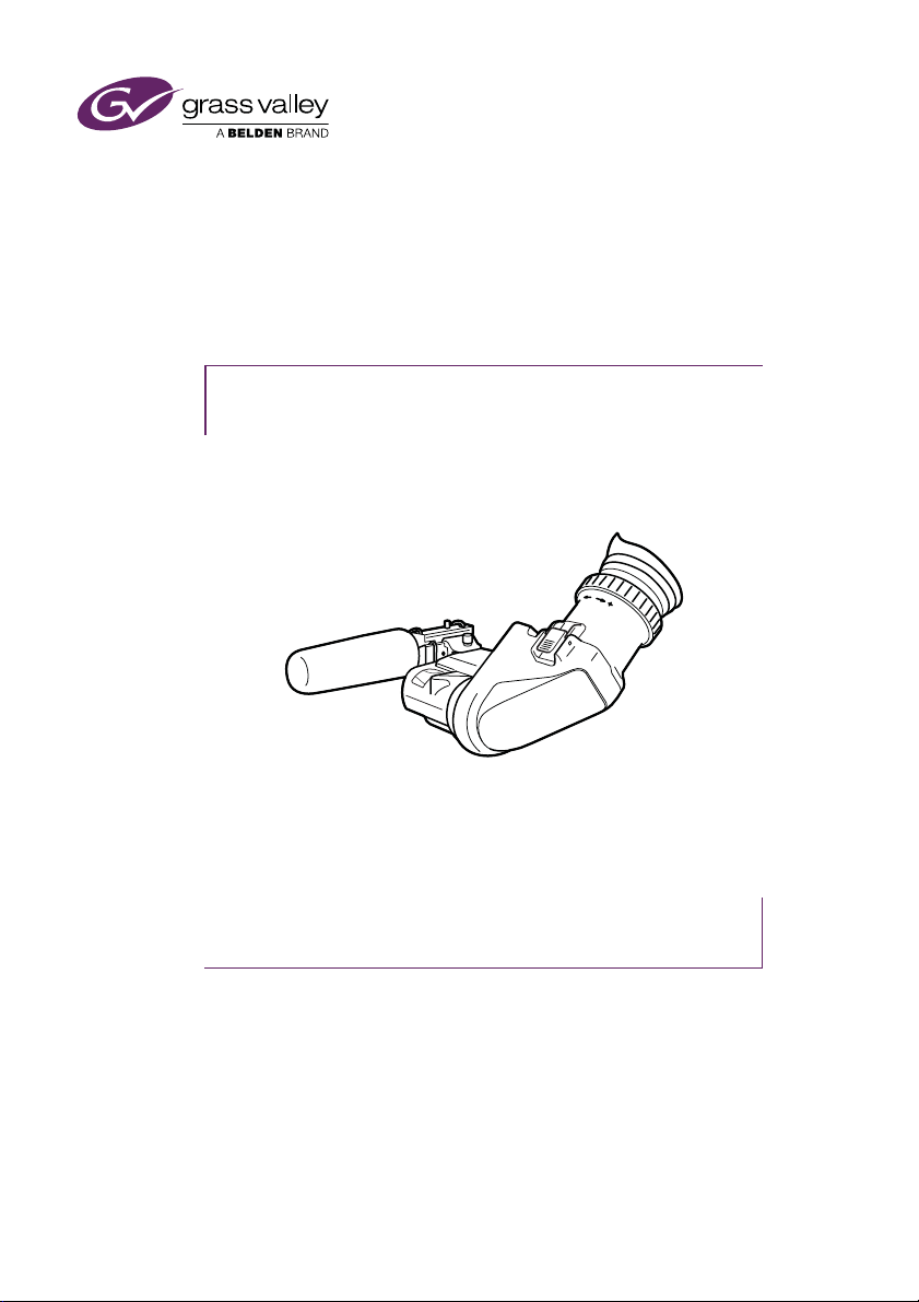
EyeCatcher EC 200 2-inch Color LCD Ocular Viewfinder User’s Guide (v1.0) 7
Wichtige Hinweise
Lesen Sie bitte diese Hinweise genau bevor Sie diese Apparatur installieren und
erhalten Sie Sie für künftiges Nachslagen. Beachten und Lesen Sie alle mit
“Achtung” und “Vorsicht” gekennzeichneten Warnhinweise. Änderungen haben zur
Folge, dass die Garantie ungültig wird und der Benutzer für etwaige durch die
veränderte Ausrüstung verursachte Störungen haftbar gemacht werden könnte.
Sicherheit (Zusammenfassung)
Diese Informationen sind als Leitfaden für qualifiziertes Fachpersonal gedacht, das
die Gefahren beim Umgang mit potenziell gefährlicher elektrischer/elektronischer
Ausrüstung kennt. Es handelt sich dabei nicht um eine vollständige
Zusammenstellung aller Sicherheitsvorkehrungen, die beim Gebrauch dieser oder
anderer elektronischer Geräte zu beachten sind.
Wenn eine Beeinträchtigung des sicheren Betriebs wahrscheinlich ist, muss das
Gerät außer Betrieb gesetzt und gegen ungewollten Betrieb gesichert werden. Dann
muss der zuständige Kundendienst benachrichtigt werden. Eine Beeinträchtigung
der Sicherheit ist zum Beispiel dann wahrscheinlich, wenn das Gerät nicht wie
vorgesehen funktioniert oder einen sichtbaren Schaden aufweist.
Dieser Ausrüstung ist gemäß IE 60529 IP54 geschützt (Staub- und
Spritwassergeschützt).
Vorsicht
Mit “Vorsicht” wird auf eine Gefahr hingewiesen, die korrekte Arbeits- oder
Verfahrensweisen erfordert, um Tod oder Verletzung zu verhindern.
• An dieser Ausrüstung dürfen keine Änderungen vorgenommen werden;
• Es sollen nur von den Hersteller empfohlene Zubehöre verwendet werden;
• Dieses Produkt enthält keine Anwenderteile. Reparatur und Wartung nur von
qualifiziertem Fachpersonal vornehmen lassen oder nehmen Sie Kontakt auf
mit Ihrem Grass Valley Vertretene;
Achtung
Mit “Achtung” werden Arbeitsanweisungen gekennzeichnet, die zu befolgen sind,
um eine Beschädigung oder Zerstörung der Ausrüstung bzw. von Eigentum zu
verhindern.
• Dieses Produkt darf nicht an extremen stöße oder Zittern ausgesetzt werden;
• Dieses Produkt darf nicht an extremen Temperaturen ausgesetzt werden.

8 EyeCatcher EC 200 2-inch Color LCD Ocular Viewfinder User’s Guide (v1.0)

EyeCatcher EC 200 2-inch Color LCD Ocular Viewfinder User’s Guide (v1.0) 9
Chapter 1 - Installation
Chapter 1
Installation
1.1 Mounting the viewfinder
To mount the viewfinder onto the camera proceed as follows:
• Loosen locking ring (2) of viewfinder support bracket (1) at the front of the
camera handgrip. (As seen from the rear of the camera, turning the locking ring
counterclockwise moves it towards the handgrip.)
• Push the locking pin (3) in and slide the viewfinder onto the viewfinder support
bracket (1).
• Tighten the locking ring (2) by turning it clockwise (as seen from rear) so that
the viewfinder is mounted securely to the support.
Tip
To improve the comfort of the skin contact when using the viewfinder, fit the eye
piece cover to the rubber eyepiece. Spare eye piece covers are available via your
Grass Valley representative.
3
1
2

10 EyeCatcher EC 200 2-inch Color LCD Ocular Viewfinder User’s Guide (v1.0)
Chapter 1 - Installation
• Connect the viewfinder cable to the viewfinder connector socket (1) at the top
right of the camera.
• Attach the microphone holder (2) onto the viewfinder and secure with the
knurled screw (3).
Tip
Guide the viewfinder cable along the front of the camera and attach it to one of the
cable clips.
1
3
2

EyeCatcher EC 200 2-inch Color LCD Ocular Viewfinder User’s Guide (v1.0) 11
Chapter 1 - Installation
1.2 Positioning the viewfinder
The horizontal position of the viewfinder can be adjusted as follows to suit your
requirements:
• Loosen the locking ring (1). As seen from the rear of the camera, turning the
locking ring counterclockwise moves it towards the handgrip.
• Slide the viewfinder horizontally along the rail to the desired position.
• Tighten the locking ring (1) by turning clockwise.
The viewfinder can be positioned backwards and forwards along the camera axis:
• Loosen the support bracket round bar retaining lever (3).
• Slide the round bar (2) forwards or backwards.
• When the desired position is reached tighten the round bar retaining lever (3)
again.
1
2 3

12 EyeCatcher EC 200 2-inch Color LCD Ocular Viewfinder User’s Guide (v1.0)
Chapter 1 - Installation
Distance viewing
The viewfinder display can also be viewed from a distance :
• Push down the bottom clip (4) below the eyepiece and swing it free of the
associated clip.
• The eyepiece can also be swung downwards; push down the top clip to
release the eyepiece and swing it downwards.
Note
Handle the eyepiece with care when folded back—its position is not secured.
4

EyeCatcher EC 200 2-inch Color LCD Ocular Viewfinder User’s Guide (v1.0) 13
Chapter 2 - Operation
Chapter 2
Operation
2.1 Controls
2.1.1 Rear panel
Mode switch
This switch determines the function of the Menu-Peak rotary control below. Set the
Mode switch to the right (Peak) to adjust peaking level. Set the Mode switch to the
left (Menu) to use the rotary for menu navigation.
Menu- Peak On Off
TallyMode SW C
Off Hi
321
87
4 5 6
1

14 EyeCatcher EC 200 2-inch Color LCD Ocular Viewfinder User’s Guide (v1.0)
Chapter 2 - Operation
Tally switch
This switch is used to control the tally indicators at the front of the viewfinder and
the rear of the handgrip. The toggle switch has three settings: Off, Low (middle
position) and Hi.
When the switch is set to the Off position, the tally indicator does not light even
when the camera is On Air.
Switch C (underscan)
Set this toggle switch to On to see an underscan or scaled down (to approximately
85% of the area) picture in the viewfinder. This allows for a greater viewing distance
from the eyepiece. A blue border around the picture and the message “underscan”
appear. Set the switch to Off to return to the original picture.
Menu-Peak control
When the Mode switch (1) is set to Peak, this rotary control adjusts the peaking
level (sharpness) of the viewfinder picture.
Tip
It may be necessary to reduce peaking when the camera gain is set to high values.
When the Mode switch (1) is set to Menu, the rotary is used for navigating the
viewfinder menu. Refer to Section 2.3 on page 20 for more information about the
menu and to navigate it.
Contrast control
Turn this rotary control clockwise to adjust the contrast of the viewfinder picture
according to your preferences. The range runs from 0 (low contrast) to 99 (high
contrast).
Brightness control
Turn this rotary control clockwise to adjust the brightness of the viewfinder picture
according to your preferences. The range runs from 0 (very dark) to 99 (very bright).
Dioptre adjustment ring
The dioptre of the viewfinder can be adjusted to suit your eyesight by turning the
dioptre adjustment ring. Turn to the right for negative dioptre values, turn to the left
for positive values.
Rear tally indicator
This indicator lights to indicate that the camera is On Air. This indicator has the same
function as the front tally indicator.
2
3
4
5
6
7
8

EyeCatcher EC 200 2-inch Color LCD Ocular Viewfinder User’s Guide (v1.0) 15
Chapter 2 - Operation
2.1.2 Front panel
User button A
This user button can be assigned in the viewfinder menu.
User button B
This user button can be assigned in the viewfinder menu.
Front tally indicator
This indicator (and one at the rear of the handgrip of the camera) lights to indicate
that the camera is On Air.
A
B
1 2 3
1
2
3

16 EyeCatcher EC 200 2-inch Color LCD Ocular Viewfinder User’s Guide (v1.0)
Chapter 2 - Operation
2.2 Indicators
2.2.1 LED indicators
Return indicator
Lights when a return video channel is switched on in the camera.
Battery power indicator
Lights if the camera input voltage is too low (when using a battery).
Call indicator
The green LED lights to attract attention when a Call signal is activated.
ISO indicator
The yellow LED lights to indicate that the camera is currently in ISO mode (yellow
On Air or Isolate)
On Air indicator
The red LED lights to indicate that the camera is currently On Air.
ZoomPickMe
PickMe
Call
On AirISO
Call
On AirISO
REND
Foc+
Gain
Bat tRet
[!]
7 8
119 10 12 13
1 2 3 4 5 6
1
2
3
4
5

EyeCatcher EC 200 2-inch Color LCD Ocular Viewfinder User’s Guide (v1.0) 17
Chapter 2 - Operation
PickMe indicator
This yellow LED lights when a PickMe signal is activated.
Zoom indicator
Lights when the viewfinder Zoom function is on.
Focus Assist indicator
Lights when the focus assist function is on (turn on in the camera menu).
Range Extender indicator
Lights when a range extender is selected.
ND filter indicator
Lights when an ND (neutral density) optical filter is selected.
Studio signalling indicators
Mirrored indicators from the top row (Call, ISO, On Air and PickMe) for improved
viewing range.
Gain indicator
Lights when gain is lower than 0 dB or higher than +3 dB
Non-standard indicator
The non-standard video settings indicator lights when one of the following
conditions occur:
– Exposure time is not set to the nominal value.
– Black Stretch is on.
– Extended Auto Iris is on.
– AWC (continuous automatic white balance) or FL (fluorescent) color
temperature is on.
6
7
8
9
10
11
12
13

18 EyeCatcher EC 200 2-inch Color LCD Ocular Viewfinder User’s Guide (v1.0)
Chapter 2 - Operation
2.2.2 On screen indicators
Go to the camera menu to select the indicators you wish to see in the viewfinder
screen.
Zoom indicator
Indicates the percentage to which the lens has been zoomed out or in, ranging from
0 (wide) to 99 (tele). It shows 50 if the lens does not support this feature.
Iris indicator
Shows the iris opening (or F-value) of the lens. Typical range is F1.4 to F25. The
indicator shows ‘Closed’ when the lens is closed or capped.
Focus indicator
Shows the percentage of the lens focus distance. Typical range is from 0 (close-up)
to 99 (infinity).
Precision Focus (PF) indicator
Shows the Precision Focus indicator (if supported by the lens).
Filter indicator
Shows the selected optical filters (ND and FX).
Depth of Field (DOF) indicator
Shows Depth of Field of the current lens position. F = Far limit in meters, N = near
limit in meters. Ntoe: not all cameras support this feature.
55
16 Sf N:0.68m
F:1.3 5 m
+
F
5.6
60
12a 2b
4a 4b3
1
2a
2b
3
4a
4b

EyeCatcher EC 200 2-inch Color LCD Ocular Viewfinder User’s Guide (v1.0) 19
Chapter 2 - Operation
2.2.3 On screen markers
Go to the camera system menu to select the markers you wish to see in the
viewfinder screen.
Cadre
A dotted white line or a shaded area that shows the limits of a 4:3 (15:9 or 14:9)
picture.
Safe area
Encloses an area that represents 80% of the whole viewfinder picture area. This is
the minimum area seen on a TV-set.
Centre cross
Marks the centre of the picture.
ZoomPickMe
PickMe
Call
On AirISO
Call
On AirISO
REND
Foc+
Gain
Bat tRet
[!]
1 2 3
1
2
3

20 EyeCatcher EC 200 2-inch Color LCD Ocular Viewfinder User’s Guide (v1.0)
Chapter 2 - Operation
2.3 Viewfinder menu
2.3.1 Entering the menu
Many viewfinder functions can be set up in the viewfinder menu. Enter the menu as
follows:
• Make sure the mode switch on the rear panel is set to Menu (left position).
• Press the menu rotary to open the menu. A black bar with menu items
appears at the bottom of the viewfinder screen.
• Use the menu rotary to navigate to the PREV/NEXT item at the right side of
the screen.
• Press the rotary to open a list of submenus. The PREV/NEXT item is blinking.
• Turn the menu rotary to loop through the submenus. The submenus are
shown on the bottom bar.
• Press the menu rotary to leave the list and enter the selected submenu.
• Turn the menu rotary to loop through the items in the menu.
• Press to change the value of the selected item. Items with toggle values are
changed immediately. Items with select values start blinking and their value
can be changed by turning the rotary. Pressing stores the current value.
• When you are done making changes, navigate to the EXIT MENU item at the
left side of the screen. Press to leave the viewfinder menu. The black bar
disappears.
Buttons
Config1
Diag
Config2
Color
Mono
Box
CONFIG2
EXIT
<Off>
Text
<Whit>
PkCol INDADJ
NEXT
PREV
Table of contents
Other Belden Camera Accessories manuals
Popular Camera Accessories manuals by other brands

PDMOVIE
PDMOVIE LIVE AIR 3 SMART Product user manual

ORION TELESCOPES & BINOCULARS
ORION TELESCOPES & BINOCULARS Solar StarSeeker 10382 instruction manual

Dynex
Dynex DX-TRPFLX Guide d'installation rapide

Choo Choo Vision
Choo Choo Vision PAN-CAM user manual

Energizer
Energizer Eveready 246 datasheet

PROAIM
PROAIM P-PRT-D Assembly manual