BELFOR SOLUS-500 Operating instructions

SOLUS-500
EXTRACTOR
120V
INFORMATION
&
OPERATING
INSTRUCTIONS
DO NOT OPERATE MACHINE UNTIL YOU HAVE READ
ALL SECTIONS OF THIS INSTRUCTIONS
IMPROPER USE OF THE MACHINE WILL VOID THE WARRANTY
1. Always use a defoamer when foaming occurs to prevent vacuum motor damage.
2. Keep machine from rain and snow, extremes in temperatures, and store in a heated
location. DO NOT let the machine or the wand freeze. Do not use outdoors.
3. Do not let the pump run dry.
4. Use approved chemicals only. NO SOLVENTS.
5. Wear gloves or use rags when removing quick disconnects to prevent burns.
6. Never use water above 130 ºF/54 ºC in the solution tank.
revised 5/11 Form No. 56041867
MODEL: SOLUS-500-B

FORM NO. 56041867 - SOLUS 500 B - 3
IMPORTANT SAFETY INSTRUCTIONS
This machine is only suitable for commercial use, for example in hotels, schools, hospitals, factories, shops and offices other
than normal residential housekeeping purposes.
When using any electrical appliance, basic precautions should always be followed, including the following:
NOTE: Read all instructions before using this machine.
WARNING!
To reduce the risk of fire, electric shock, or injury:
•Do not leave the machine unattended when it is plugged in. Unplug the unit from the outlet when not in use and before
servicing.
•To avoid electric shock, do not expose to rain or snow. Store and use, indoors.
•Do not allow to be used as a toy. Close attention is necessary when used near children.
•Use only as described in this manual. Use only the manufacturer’s recommended attachments.
•Never add water over 130º F/54º C to the solution tank.
•Do not use with damaged cord or plug. If the machine is not working as it should, has been dropped, damaged, left
outdoors or dropped into water, return it to a service center.
•Do not pull by the cord, use the cord as a handle, close a door on the cord, or pull the cord around sharp edges or corners.
Do not run the machine over the cord. Keep the cord away from heated surfaces. To unplug, grasp the plug, not the
cord.
•Do not handle the plug, the cord or the machine with wet hands.
•Extension cords must be 12/3 and no longer than 50 feet. Replace the cord or unplug immediately if the ground prong
becomes damaged.
•Do not put any object into openings. Do not use with any opening blocked; keep free of dust, lint, hair, and anything that
may reduce air flow.
•Keep loose clothing, hair, fingers, and all parts of body away from openings and moving parts.
•Do not pick up anything that is burning or smoking, such as cigarettes, matches, or hot ashes, or any health endangering
dusts. Do not use to pick up flammable or combustible liquids such as gasoline or use in areas where they may be
present.
•Turn off all controls before unplugging.
•Use extra care when cleaning on stairs.
•Connect to a properly grounded outlet only.
•Liquid ejected at the spray nozzle could be dangerous as a result of its temperature, pressure, or chemical content.

4- FORM NO. 56041867 - SOLUS 500 B
INSPECTION:
Carefully unpack and inspect your SOLUS-500 for shipping damage. Each machine is tested and inspected before shipping.
Any shipping damage incurred is the responsibility of the carrier. You should notify the carrier immediately if you notice dam-
age to the box or to the machine or parts.
CLEANING SOLUTIONS:
We recommend liquid cleaning chemicals. Powder chemicals may be used, but unless mixed very thoroughly they could
cause a build-up in the pump, lines, heat exchanger and/or quick disconnects. Any problem caused by a chemical build-up is
not covered by warranty. Use a neutral cleaner with a pH between 5 and 10 to avoid premature wear of the pump, seals, and/
or other components. Damage caused by the use of strong chemicals is not covered by the warranty.
MAINTENANCE:
For optimum performance flush the machine with clear water at the end of each working day. Once a month, minimum, run
a flushing compound through the machine to break up any mineral or chemical build-up that may have formed. The vacuum
motor, pump motor, and the pump do not require any scheduled maintenance; however, the motors may require replacement
brushes after 1000 - 1500 hours, and the pump and bypass valve may require rebuild kits after 1000 - 1500 hours, typically
(refer to machine part list for numbers). Clean the body with an all-purpose detergent, and protect it with an automobile inte-
rior polish. Lubricate the wheels, castors, and quick disconnects with an all purpose silicone spray.
PARTS AND SERVICE:
Repairs, when required, should be performed by your authorized distributor who maintains an inventory of original replace-
ment parts and accessories. Call the distributor from whom you purchased this machine if you need parts and service. Be
sure to specify the machine model. Have your serial number handy.
SERIAL NUMBER: __________________
MODEL: SOLUS-500-B
PURCHASE DATE: __________________
NAME AND PHONE NUMBER OF YOUR DISTRIBUTOR:
____________________________________________
____________________________________________
(Be sure to register your purchase to activate your warranty)
MODIFICATIONS
Modifications and additions to the cleaning machine which affect capacity and safe operation shall not be performed by the
customer or user without prior written approval from the manufacturer. Unapproved modifications will void the machine warranty
and make the customer liable for any resulting accidents.
FORM NO. 56041867 - SOLUS 500 B - 5
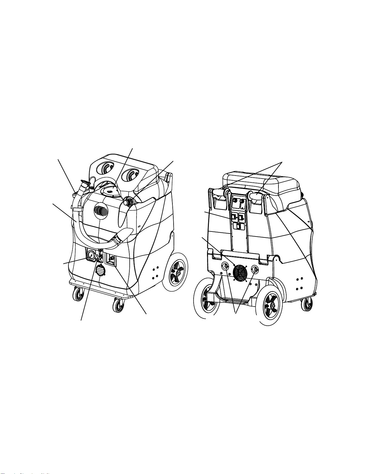
DRAIN
HOSE
HANDLES
VACUUM HOSE
BARB
FAN
VACUUM
LID
12” WHEEL
LATCH
SOLUTION HOSE
QUICK COUPLING
SWITCH
PLATE
CASTOR
SOLUTION
TANK FILL
HOLE
PSI
GAUGE
POWER CORD
RECEPTICLES
KNOW YOUR MACHINE
VACUUM LID - This lid provides access into your recovery tank so that you can clean the tank. The lid must be closed
before you try to clean.
SOLUTION TANK FILL HOLE - This is where you fill the tank with water and cleaning solution.
VACUUM HOSE BARB - This is where you connect your vacuum hose to the machine. A tight connection is necessary
to prevent a vacuum leak which would reduce the amount of suction.
DRAIN HOSE - This is how you empty the dirty water from your recovery tank. Place the hose over a drain, and open
the cap. When cleaning out the tank at the end of a job, simply place this hose into a drain and use clean water to
rinse out the dirt and debris from the tank. NOTE: be sure to close the cap tightly before using the machine again.
HANDLES - The handles are used to move the machine. These handles allow you to tilt the machine back onto its
12” wheels for easy maneuvering, and/or for moving on stairways.
SWITCH PLATE - The switches are located on the rear of the machine, out of the way of water.
FAN - Removes warm air from the component compartment.
PSI GAUGE - indicates the pump pressure. Look at the pressure while you spray.
LATCH - The latch holds together the tank and the base compartment.
SOLUTION HOSE QUICK COUPLING- This is where you connect the solution line that runs from the machine to the
carpet wand or hand tool.
POWER CORD RECEPTACLES - The receptacles are where the two power cords connect to the machine.
CASTOR - Swivel castor provides easy maneuverability.
WHEEL - The rear wheels are 12 inches in diameter to provide superior ease of transportation and stair climbing.
6- FORM NO. 56041867 - SOLUS 500 B
13
4
6
2
5
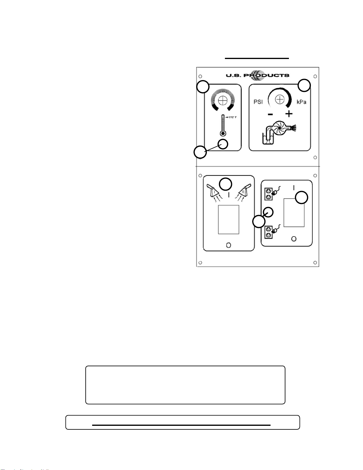
SWITCH PLATE
HEAT CONTROL (1):
This dial controls the water temperature. Turn it clockwise
to increase water temperature and counterclockwise to
decrease temperature. The heater will operate only if the
circuit locator light (#5) or the bypass switch (#6) is on.
HEAT MODE LIGHT (2):
This light will only illuminate when the heater is heating and
will turn off when it reaches operating temperature. During
normal operation, the “MODE” light will be on most of the
time.
PUMP CONTROL (3):
This dial controls motor speed and pump pressure. Adjust
the dial clockwise to increase pressure and counterclockwise
to decrease pressure or turn off pump. The pump runs off of
cord #1. The pump spraying pressure will be observable at
the pressure gauge.
VACUUM SWITCH (4):
This switch will illuminate when the vacuum motors are on.
The vacuum motors run off of cord #1.
CIRCUIT LOCATOR (5):
When this light is on, it indicates that cord #2 (Identified by
the red “H” on the back of the extractor.) is on a separate
line from cord #1. Cord #2 supplies voltage to the heater
allowing it to heat to the temperature range indicated by the
Heat Control dial (#1) on the switch plate.
BYPASS SWITCH (6):
The bypass switch will illuminate when it is activated and
will completely bypass the circuit locator system. Use this
system only when the circuit locator light will not turn on and
you know each cord is on a separate circuit.
CAUTION: THE CIRCUIT BREAKER CAN TRIP IF BOTH CORDS
ARE ON THE SAME CIRCUIT AND THE BYPASS (heat) SWITCH IS
TURNED ON.
NEVER LET YOUR MACHINE OR YOUR WAND FREEZE
SOLUS-500
SWITCH PLATE

FORM NO. 56041867 - SOLUS 500 B - 7
SET-UP AND OPERATION:
1. Fill the holding tank with clear water and pre-spray with the detergent of your choice (we recommend a CRI approved chemical). Mix
well. Although this machine is designed to supply instant hot water, the addition of warm water to the holding tank would increase heater
efficiency.
Never use water above 130º F/54º C in the solution tank.
2. Turn off all the switches. Plug in cord #1. (This cord runs the pump and vacuum).
3. Attach the priming hose to the machine and place the open end into the tank.
4. Turn on the pump (turn pump pressure dial all the way clockwise) and let it run until the pump is fully primed (approximately 30
seconds to 1 minute). Once the pump is primed, turn off the pump and disconnect the priming hose. Attach the cleaning hose and tool.
IF YOU WANT HEATED SOLUTION:
5. Plug in the heater cord (identified by “H” on the back of the machine). NOTE: If the green circuit indicator light does not
illuminate when the heater cord is plugged in, then both cords are on the same circuit. Try other outlets until the light comes on.
See Bypass Switch section (below) if you are unable to get a green light.
6. Turn the heat knob clockwise to the desired temperature.
7. Turn on the pump and spray through your tool a few times to fill the lines with solution. Begin cleaning.
8. Refill and empty the tanks as necessary.
9. When finished with the job, vacuum all unused solution into the recovery tank, and dump the tank. Clean the tanks and filters. Clean
the tool and hoses. Store the machine in a heated location.
ELECTRIC CIRCUIT LOCATOR:
This unique, patented “smart system,” operated by a solid state circuit, will inform the operator when the two cords are plugged into
separate lines by illuminating the green, indicator light. This helps prevent tripping circuit breakers.
BYPASS SWITCH:
The bypass switch (#6) completely bypasses the circuit locator system. Use this feature when you cannot get the green Locator
light (#5) to come on and you believe that the two cords are on separate circuits.
CAUTION: If the bypass switch is on when the two cords are plugged into the same circuit, the breaker in the
wall panel may trip.
AUTO VACUUM SHUTOFF:
When the recovery tank is full, the float system will shut off the vacuum motor to prevent the machine from overflowing. The float
may not work in foam. Always use a defoamer to prevent overflow. Once the vacuum motor shuts off, the vac switch (#7) must be
turned off, the recovery tank emptied, and then the vacuum switch turned back on (up position) to get the vacuum motor started
again.
CAUTION: Always make sure the float is clean and travels freely before turning on the machine. A float that is
stuck will cause the vacuum motor to suck in water, resulting in vac motor damage.
PUMP PRESSURE:
Make sure the cleaning tool is spraying when adjusting the pressure, otherwise the pressure reading will be inaccurate.
8- FORM NO. 56041867 - SOLUS 500 B revised 11/10
SOLUS-500-B
21
33
8
25 18
26
28
31
45
36
37
40
38
46
55
57
56 58
62
60
64 66
67
68
53
52
73
70
72
51
50
49
1
5
3
3A
7
6
5A
6A
29
28A
31
24
12
16
18
15
14
19
20
22
19
13
17
11
10
75
74
71
77
PUMP
9
26
34
63
54
44 42 41
43
65
15A
{
9A
13A
23
Pump inlet
hose
Pump bypass
hose
69
78
81
82
83

FORM NO. 56041867 - SOLUS 500 B - 9
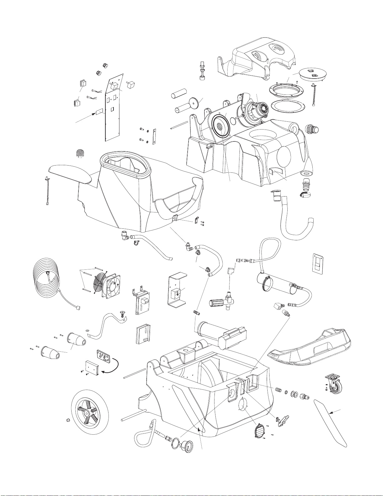
SOLUS-500-B
Item Ref. No. Qty Description
1 FP578 2 Switch, DPDT, with cover
[ ] 1 Switch Rocker DPST W/Light 120
[ ] 1 Sheet, Instruction, Switch
3 78B 1 Light, red
3A 78 1 Light, green
5 248 1 Knob, red
5A FP544 1 Potentiometer, heat, w/wires & knob
[ ] 1 Potentiometer, 10K for Heat
[ ] 1 Knob, with Red Top for 1/4
[ ] 39in Wire, Yellow, 18 Gauge 500
[ ] 37in Wire, Red 18 Gauge
6 249 1 Knob, blue
6A FP543 1 Potentiometer, pump, w/wires & knob
7 2093A 1 Switch plate
8 4404D 1 Mating bar
9 2106 2 Handle
9A 1590 2 Grip, handle
10 2105 2 Wheel, handle
11 FP478 1 Float, electric, water level
12 801E 2 Hinge pin 7”
13 VUPE-B 1 Tank, Vacuum
13A VC-BLK1 1 Cover, for vacuum motors
14 2013A 2 Gasket, vacuum
15 408E 2 Vacuum motor, 120V
15A 1589 2 Screen, 1/8 S/S mesh
16 2086A 1 Lid & ring, vacuum
[ ] 1 O-Ring for 2086A Lid
[ ] 1 Lid
[ ] 1 Mounting Plate
17 1074 1 Gasket, vacuum lid
18 FP436 1 Chain, 8”
19 907 1 Hose barb, 1-1/2”
20 1130 2 Strap, Velcro, 9”
21#56113071 1 Plug-Hose
22 1518 1 Hose Clamp
23 1060B 1 Hose, drain
24 HUPE-B 1 Tank, Holding
25 LUPE-B 1 Lid, Holding Tank
26 909A 1 Latch strike
28 1113 1 Hose barb, 90°, 1/2” hose
28A 1115 1 Hose barb, 90°, 3/8” hose
29 925 1 Hose, 3/8” ID X 17”
31 166 4 Hose clamp
33 946 1 Hose, 1/2” ID X 20”
34 207A 1 Filter, pump inlet
36 See Miscellaneous **
37 918 1 Heat Sink plate
38 FP361 1 Motor Speed Control PCB, pump
[ ] 1 Motor Speed Control
[ ] 1 Resistor-Horsepower .05 Ohm
[ ] 1 Instruction Sheet
40 FP225 1 Vacuum Motor Control PCB
41 2014 1 Fan, 120V
42 2015 1 Guard, fan
43 2B1 4 Screw, 6-32 X 2-1/4”
44 1057B 2 Power Cord, 12/3, 25 ft
45 1062 2 Receptacle, AC power in
46 1476 1 Strap, 17”
49 FP336 1 PCB mounting track, 4”
50 923B 1 Dual Cord Sensor PCB
51 198 1 Hose clamp
52 948B 1 Motor, DC, for pump
Item Ref. No. Qty Description
53 FP592 1 Pump complete, no mtr
[ ] 1 Pump, Piston Style, 300-500 Psi
[ ] 1 Bearing & Cam Assembly
[ ] 2 Quick Connect, Plug, Brass
[ ] 1 Nipple, 1/4 Pipe, Brass
[ ] 1 Hose Barb 1/4 Pipe X 1/2 Hose
[ ] 1 Hose Barb, 90, Brass, 3/8”
[ ] 1 Elbow, 90 Degree 3/8” Brass
[ ] 1 Reducer, 3/8 Pipe Female
[ ] 2 Bushing 3/8 X 1/4 Pipe, Brass
[ ] 1 Elbow, 90 Deg 1/4” Mpt X 1/4”
[ ] 1 Plug, Brass Pipe, 1/4 Pipe
[ ] 1 Unloader Valve For 500 PSI
54 FP542 1 Hose assembly, pump to gauge
[ ] 1 Hose Pulsation Dampening 28”
[ ] 1 Quick Connect, Brass, 1/4 FPT
[ ] 1 Nipple, 1/4 Pipe, Brass
55 801D 2 Hinge pin 4.75”
56 27A 2 Axle Cap
57 2092 2 Wheel, 12”
58 910-2375 1 Axle rod
60#1 Base NOTE 1
62 905 2 Castor, 4”
63 2165 1 Gauge, Pump pressure, with QD
64 928 1 Louver, 3”, gray
65 FP585 1 Castor Plate
[ ] 1 Castor Plate Molded W/Handle Blk
[ ] 1 Instruction sheet
66#56471194 1 Latch Assembly
67 45 1 Quick Disconnect, male. 1/4 p.t.
68 115 3 Washer, fiber
69 116A 1 Bushing, Teflon
70 92A 2 Nipple, 1/4 p.t. S/S
71 216 1 Elbow Brass
72 FP540 1 Heat Exchanger, complete
73 455 1 Mount bracket, heater
74 223 1 Quick Disconnect, male
75 945D 1 Unloader valve
77 FP547 1 Hose assembly, heater inlet
[ ] 1 Hose Assy, Swivel 48F to 4-6
[ ] 1 Elbow 90 Deg 1/8 x 1/8 P. Brass
78 2183 1 Hose, S/S, braided, heater outlet
81 56380994 1 Label-Belfor-Solus-Left
82 56380993 1 Label-Belfor-Solus-Right
83 56380692 1 Label, Danger Electric Shock
[ ] 4344 1 Label Gauge Priming Warning
[ ] 4325C 1 Label Heat Designation Power
[ ] 4339 1 Label Caution / Extension Cord
MISCELLANEOUS PARTS
Item Ref. No. Qty Description
** FP194E 1 Heat repair kit includes thermistor
control, thermistor probe & cutout
** 950CP 1 Pump rebuild kit, valves & o-rings
** 250 1 Pump rebuild kit, piston & seals
** FP538 1 Pump & motor complete w/unloader
[ ] 1 Plug Brass Pipe 1/4 Pipe H
[ ] 1 Elbow 90 Deg 1/4 Mpt X 1/4
[ ] 1 Elbow 90 Degree 3/8 Brass
[ ] 2 Bushing 3/8 X 1/4 Pipe Brass
[ ] 2 Reducer 3/8 Pipe Female To 1
[ ] 1 Tee Brass 1/4 Pipe
[ ] 4 Capscrew 1/4-20 X 2 X 1
[ ] 2 Quick Connect Plug Brass 1/
[ ] 1 Hose Barb 90 Brass 3/8 Ba
[ ] 1 Hose Barb 1/4 Pipe X 1/2 Hose.
[ ] 1 Nipple Pipe Stainless Steel 1/
[ ] 1 Unloader Valve For 500 Psi Pum
[ ] 1 Motor Dc Volt100v 300/500 P
[ ] 1 Bearing & Cam Assembly Size.0
[ ] 1 Pump Piston Style 300-500 Ps
[ ] 1 Thermostat Probe 120v. Tempert
** FP619 1 Bag, Pre-filter for recovery inlet
Parts in kits are not sold separately.
#= Revised or new since last update
[ ] = Not Shown
** = Optional, Not Included
revised 5/11
#NOTE 1: Order part number 56381643 “Solus-500 Base Drill Complete”.
10 - FORM NO. 56041867 - SOLUS 500 B
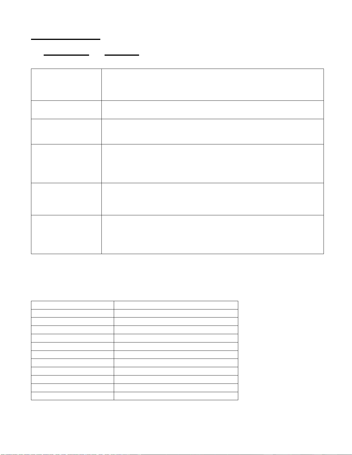
If you can not solve the problem from this chart, contact the distributor from whom you purcahsed your machine
TROUBLESHOOTING:
IF THIS OCCURS CHECK THIS
NO SPRAY
Solution tank is empty.
Clogged spray tip.
Pump not running or not primed.
Valve on wand not operating.
PUMP DOES NOT RUN
Check the brushes in the pump motor. Replace if necessary.
No power to pump. Test the Motor Speed Control Circuit Board and potentiometer.
LOW SUCTION
Debris is plugging cleaning tool or vacuum hose.
Drain gate is not completely closed, or seals are damaged.
Vacuum dome is not seated or is damaged.
NO SUCTION
No power to motor.
Test the Electronic Float.
Test the switch.
Test the vacuum motor.
Test the Vacuum Circuit Board.
LOW HEAT
Spraying too long. Try spraying for 12-15 seconds, or about three strokes.
Heat exchanger needs to be flushed.
Wrong tool being used. Too much water passing through. Longer hose or larger diameter hose, than
standard.
NO HEAT
Heat is not turned on. Either the green light must be on or the bypass switch must be turned on.
No power in the wall outlet - check to see if the breaker has tripped.
No power to the bypass switch - check wiring for ‘opens.”
No power out of bypass switch, follow troubleshooting steps to isolate the problem.
Call your distributor for additional help.
TECHNICAL SPECIFICATIONS (as installed and tested on the unit)
Model Solus 500 Belfor
Model No. SOLUS-500-B
Roto-molded Body Lifetime Warranty
Vacuum Two 5.7”, 3-stage
VAC Shutoff Electronic
Pump Positive displacement, fully adjustable 0-500 psi
Waterlift 100” -- 170 CFM
Heat Adjustable to 212º F
Heater 2000 Watts
Wand Stainless steel, double bend, twin tip
Weight 110 lbs.
Dimensions 24W x 28L x 41H (inches)

NOTES:
SOLUS-500
EXTRACTOR
120V
This manual suits for next models
1
Table of contents


