BELIMED WD 290 User manual

Technical Manual &
Installation Instructions
WD 290
Material number: 10521-581/010-EN
Version: 003-04/17

2/177 WD 290
10521 © Belimed
Table of contents
1 Introduction . . . . . . . . . . . . . . . . . . . . . . . . . . . . . . . . . . . . . . . . . . . . 8
1.1 Read the instructions . . . . . . . . . . . . . . . . . . . . . . . . . . . . . . . . . . . . . 8
1.2 Target group . . . . . . . . . . . . . . . . . . . . . . . . . . . . . . . . . . . . . . . . . . . . 8
1.3 Changes . . . . . . . . . . . . . . . . . . . . . . . . . . . . . . . . . . . . . . . . . . . . . . . 8
1.4 Symbols and references used. . . . . . . . . . . . . . . . . . . . . . . . . . . . . . . 8
2 Basic safety instructions . . . . . . . . . . . . . . . . . . . . . . . . . . . . . . . . . 9
2.1 Intended use . . . . . . . . . . . . . . . . . . . . . . . . . . . . . . . . . . . . . . . . . . . . 9
2.2 Exercise duty of care. . . . . . . . . . . . . . . . . . . . . . . . . . . . . . . . . . . . . . 9
2.3 Operation only by authorized personnel . . . . . . . . . . . . . . . . . . . . . . . 9
2.4 Safety instructions on the machine . . . . . . . . . . . . . . . . . . . . . . . . . . . 9
2.5 Observe fields of application. . . . . . . . . . . . . . . . . . . . . . . . . . . . . . . 10
2.6 Safety through process validation. . . . . . . . . . . . . . . . . . . . . . . . . . . 10
3 Machine specifications. . . . . . . . . . . . . . . . . . . . . . . . . . . . . . . . . . 11
3.1 Machine dimensions . . . . . . . . . . . . . . . . . . . . . . . . . . . . . . . . . . . . . 11
3.2 Machine dimensions with condenser or PW tank (optional) . . . . . . . 12
3.3 Optional additional components . . . . . . . . . . . . . . . . . . . . . . . . . . . . 13
3.3.1 Options (only available ex-factory) . . . . . . . . . . . . . . . . . . . . . . . . . . 13
3.3.2 Options that can be upgraded in the field . . . . . . . . . . . . . . . . . . . . . 13
3.3.3 Paneling . . . . . . . . . . . . . . . . . . . . . . . . . . . . . . . . . . . . . . . . . . . . . . 13
3.3.4 Further accessories. . . . . . . . . . . . . . . . . . . . . . . . . . . . . . . . . . . . . . 14
3.4 Technical data . . . . . . . . . . . . . . . . . . . . . . . . . . . . . . . . . . . . . . . . . . 15
3.5 Surrounding conditions . . . . . . . . . . . . . . . . . . . . . . . . . . . . . . . . . . . 16
3.5.1 Storage . . . . . . . . . . . . . . . . . . . . . . . . . . . . . . . . . . . . . . . . . . . . . . . 16
3.5.2 Transport. . . . . . . . . . . . . . . . . . . . . . . . . . . . . . . . . . . . . . . . . . . . . . 16
3.5.3 Location. . . . . . . . . . . . . . . . . . . . . . . . . . . . . . . . . . . . . . . . . . . . . . . 16
3.6 Connection modules . . . . . . . . . . . . . . . . . . . . . . . . . . . . . . . . . . . . . 17
3.6.1 General electrical power supply conditions. . . . . . . . . . . . . . . . . . . . 17
3.6.2 Electrical connections . . . . . . . . . . . . . . . . . . . . . . . . . . . . . . . . . . . . 17
3.6.3 Water connections. . . . . . . . . . . . . . . . . . . . . . . . . . . . . . . . . . . . . . . 18
3.6.4 Steam . . . . . . . . . . . . . . . . . . . . . . . . . . . . . . . . . . . . . . . . . . . . . . . . 19
3.6.5 Exhaust air . . . . . . . . . . . . . . . . . . . . . . . . . . . . . . . . . . . . . . . . . . . . 19
3.6.6 RS232, RS485 … interfaces. . . . . . . . . . . . . . . . . . . . . . . . . . . . . . . 19
3.6.7 Connection requirements for installation . . . . . . . . . . . . . . . . . . . . . 20
3.6.8 Connections in general . . . . . . . . . . . . . . . . . . . . . . . . . . . . . . . . . . . 21
3.6.9 Top connection type (ceiling). . . . . . . . . . . . . . . . . . . . . . . . . . . . . . . 22
3.6.10 Bottom connection type (floor) . . . . . . . . . . . . . . . . . . . . . . . . . . . . . 23
3.6.11 Electrical function diagram . . . . . . . . . . . . . . . . . . . . . . . . . . . . . . . . 24
3.6.12 Function diagram of steam heating with steam drying . . . . . . . . . . . 25
3.6.13 Flow diagram. . . . . . . . . . . . . . . . . . . . . . . . . . . . . . . . . . . . . . . . . . . 26
3.6.14 Type plate . . . . . . . . . . . . . . . . . . . . . . . . . . . . . . . . . . . . . . . . . . . . . 27
4 Setting up the machine. . . . . . . . . . . . . . . . . . . . . . . . . . . . . . . . . . 28
4.1 Placement of the machine (only concerns the single-door machine). 28
4.2 Unloading the machine . . . . . . . . . . . . . . . . . . . . . . . . . . . . . . . . . . . 29
4.3 Setting up the machine . . . . . . . . . . . . . . . . . . . . . . . . . . . . . . . . . . . 30

WD 290 3/177
© Belimed 10521
4.4 Machine paneling . . . . . . . . . . . . . . . . . . . . . . . . . . . . . . . . . . . . . . . 31
4.5 Protective earth connection. . . . . . . . . . . . . . . . . . . . . . . . . . . . . . . . 32
5 Installation . . . . . . . . . . . . . . . . . . . . . . . . . . . . . . . . . . . . . . . . . . . . 33
5.1 Process validation IQ (installation qualification) . . . . . . . . . . . . . . . . 33
5.2 Electrical connections . . . . . . . . . . . . . . . . . . . . . . . . . . . . . . . . . . . . 33
5.3 Sanitary connections. . . . . . . . . . . . . . . . . . . . . . . . . . . . . . . . . . . . . 34
5.4 Exhaust air system . . . . . . . . . . . . . . . . . . . . . . . . . . . . . . . . . . . . . . 35
5.5 Steam connection (optional) . . . . . . . . . . . . . . . . . . . . . . . . . . . . . . . 36
5.6 Dosing suction line . . . . . . . . . . . . . . . . . . . . . . . . . . . . . . . . . . . . . . 36
5.7 Additional dosing pumps and empty-level indicators (optional) . . . . 37
5.7.1 Installing additional dosing pumps 3 and 4 . . . . . . . . . . . . . . . . . . . . 37
5.8 Drainage pump set (optional) . . . . . . . . . . . . . . . . . . . . . . . . . . . . . . 39
5.9 Floor pan (optional). . . . . . . . . . . . . . . . . . . . . . . . . . . . . . . . . . . . . . 39
5.9 PW tank and condensers . . . . . . . . . . . . . . . . . . . . . . . . . . . . . . . . . 39
6 Commissioning . . . . . . . . . . . . . . . . . . . . . . . . . . . . . . . . . . . . . . . . 40
7 Machine description . . . . . . . . . . . . . . . . . . . . . . . . . . . . . . . . . . . . 41
7.1 Machine loading side (LS). . . . . . . . . . . . . . . . . . . . . . . . . . . . . . . . . 41
7.2 Machine unloading side (US) (2-door version) . . . . . . . . . . . . . . . . . 42
7.3 Operating unit on loading side (LS) . . . . . . . . . . . . . . . . . . . . . . . . . 43
7.3.1 Description of loading side operating unit . . . . . . . . . . . . . . . . . . . . . 43
7.4 Unloading side (US) operating unit (2-door version). . . . . . . . . . . . . 45
7.4.1 Description of unloading side operating unit . . . . . . . . . . . . . . . . . . . 45
7.5 Process status indicator . . . . . . . . . . . . . . . . . . . . . . . . . . . . . . . . . . 46
7.5.1 Description of process status indicator . . . . . . . . . . . . . . . . . . . . . . . 46
7.6 Alphanumeric input . . . . . . . . . . . . . . . . . . . . . . . . . . . . . . . . . . . . . . 47
7.6.1 Alphanumeric input procedure . . . . . . . . . . . . . . . . . . . . . . . . . . . . . 47
7.6.2 Operating buttons . . . . . . . . . . . . . . . . . . . . . . . . . . . . . . . . . . . . . . . 48
7.7 Machine with sensors . . . . . . . . . . . . . . . . . . . . . . . . . . . . . . . . . . . . 49
8 Service modules, software configuration. . . . . . . . . . . . . . . . . . . 50
8.1 Access authorization / user levels. . . . . . . . . . . . . . . . . . . . . . . . . . . 50
8.2 Log on / off . . . . . . . . . . . . . . . . . . . . . . . . . . . . . . . . . . . . . . . . . . . . 50
8.3 Menu . . . . . . . . . . . . . . . . . . . . . . . . . . . . . . . . . . . . . . . . . . . . . . . . . 52
8.4 Automatic mode / Automatic shut-off / Self-disinfection . . . . . . . . . . 53
8.4.1 Automatic shut-off . . . . . . . . . . . . . . . . . . . . . . . . . . . . . . . . . . . . . . . 53
8.4.2 Automatic start . . . . . . . . . . . . . . . . . . . . . . . . . . . . . . . . . . . . . . . . . 54
8.4.3 Automatic self-disinfection. . . . . . . . . . . . . . . . . . . . . . . . . . . . . . . . . 55
8.5 Machine information . . . . . . . . . . . . . . . . . . . . . . . . . . . . . . . . . . . . . 56
8.6 Messages, errors . . . . . . . . . . . . . . . . . . . . . . . . . . . . . . . . . . . . . . . 57
8.7 Settings . . . . . . . . . . . . . . . . . . . . . . . . . . . . . . . . . . . . . . . . . . . . . . . 58
8.8 Cleaning screen . . . . . . . . . . . . . . . . . . . . . . . . . . . . . . . . . . . . . . . . 60
8.9 User administration . . . . . . . . . . . . . . . . . . . . . . . . . . . . . . . . . . . . . . 61
8.10 Readings. . . . . . . . . . . . . . . . . . . . . . . . . . . . . . . . . . . . . . . . . . . . . . 62
9 System Configuration. . . . . . . . . . . . . . . . . . . . . . . . . . . . . . . . . . . 63
9.1 System Configuration . . . . . . . . . . . . . . . . . . . . . . . . . . . . . . . . . . . . 63
9.2 General settings . . . . . . . . . . . . . . . . . . . . . . . . . . . . . . . . . . . . . . . . 64

4/177 WD 290
10521 © Belimed
9.3 User login . . . . . . . . . . . . . . . . . . . . . . . . . . . . . . . . . . . . . . . . . . . . . 66
9.3.1 User login . . . . . . . . . . . . . . . . . . . . . . . . . . . . . . . . . . . . . . . . . . . . . 66
9.3.2 Rack identification. . . . . . . . . . . . . . . . . . . . . . . . . . . . . . . . . . . . . . . 66
9.3.3 Cycle content identification . . . . . . . . . . . . . . . . . . . . . . . . . . . . . . . . 66
9.3.4 RS485 communication address (ICS). . . . . . . . . . . . . . . . . . . . . . . . 66
9.4 Machine parameters . . . . . . . . . . . . . . . . . . . . . . . . . . . . . . . . . . . . . 67
9.4.1 Periodic servicing . . . . . . . . . . . . . . . . . . . . . . . . . . . . . . . . . . . . . . . 73
9.4.2 Hours of operation of the air filter . . . . . . . . . . . . . . . . . . . . . . . . . . . 73
9.4.3 Door Interlock . . . . . . . . . . . . . . . . . . . . . . . . . . . . . . . . . . . . . . . . . . 73
9.4.4 Program recognition . . . . . . . . . . . . . . . . . . . . . . . . . . . . . . . . . . . . . 74
9.4.5 Drainage in the event of program termination. . . . . . . . . . . . . . . . . . 75
9.4.6 Step repetition (foam control) . . . . . . . . . . . . . . . . . . . . . . . . . . . . . . 75
9.4.7 PW tank preheating temperature / preheating time . . . . . . . . . . . . . 75
9.4.8 PW tank disinfection temperature / disinfection time. . . . . . . . . . . . . 75
9.4.9 Drainage time . . . . . . . . . . . . . . . . . . . . . . . . . . . . . . . . . . . . . . . . . . 76
9.4.10 Heating interlock tank/washing chamber. . . . . . . . . . . . . . . . . . . . . . 76
9.4.11 Delay time for water heating . . . . . . . . . . . . . . . . . . . . . . . . . . . . . . . 76
9.4.12 Drying lag time . . . . . . . . . . . . . . . . . . . . . . . . . . . . . . . . . . . . . . . . . 76
9.4.13 Steam drying . . . . . . . . . . . . . . . . . . . . . . . . . . . . . . . . . . . . . . . . . . . 76
9.4.14 Potential-free outputs K28, K57 and K58 . . . . . . . . . . . . . . . . . . . . . 77
9.4.15 Rack position delay for loading and unloading . . . . . . . . . . . . . . . . . 78
9.4.16 Adjust cycle counter . . . . . . . . . . . . . . . . . . . . . . . . . . . . . . . . . . . . . 78
9.4.17 Modification of the threshold values . . . . . . . . . . . . . . . . . . . . . . . . . 78
9.5 Program parameters . . . . . . . . . . . . . . . . . . . . . . . . . . . . . . . . . . . . . 79
9.5.1 Parameter entry overview . . . . . . . . . . . . . . . . . . . . . . . . . . . . . . . . . 80
9.5.2 Filling process M1, M2, M3, M4, M9 . . . . . . . . . . . . . . . . . . . . . . . . . 81
9.5.3 Utility M5 Drying . . . . . . . . . . . . . . . . . . . . . . . . . . . . . . . . . . . . . . . . 83
9.5.4 Condenser M6 functions . . . . . . . . . . . . . . . . . . . . . . . . . . . . . . . . . . 83
9.5.5 Preheated PW water, M9 (Final Rinse). . . . . . . . . . . . . . . . . . . . . . . 83
9.5.6 Utility MA (1 step with 4 or more phases) . . . . . . . . . . . . . . . . . . . . . 83
9.5.6 Utility MB Air controlled. . . . . . . . . . . . . . . . . . . . . . . . . . . . . . . . . . . 83
9.5.6 Utility MC Air non-vented. . . . . . . . . . . . . . . . . . . . . . . . . . . . . . . . . . 83
9.5.9 Function F0 - inactive step . . . . . . . . . . . . . . . . . . . . . . . . . . . . . . . . 86
9.5.10 Function F1 - pre-rinse . . . . . . . . . . . . . . . . . . . . . . . . . . . . . . . . . . . 86
9.5.11 Functions F2-F5, F8, FD, FE. . . . . . . . . . . . . . . . . . . . . . . . . . . . . . . 86
9.5.12 Function F9 - clean rinsing (optional IPD). . . . . . . . . . . . . . . . . . . . . 86
9.5.13 Functions F6+F7 - thermal or chemical disinfection . . . . . . . . . . . . . 86
9.5.14 Function FA - thermal disinfection A0=3000 . . . . . . . . . . . . . . . . . . . 87
9.5.15 Function FB - thermal disinfection A0=600. . . . . . . . . . . . . . . . . . . . 87
9.5.16 Function FC - thermal disinfection A0=60. . . . . . . . . . . . . . . . . . . . . 87
9.5.17 Functions FD, FE and FF . . . . . . . . . . . . . . . . . . . . . . . . . . . . . . . . . 87
9.6 Adjustment . . . . . . . . . . . . . . . . . . . . . . . . . . . . . . . . . . . . . . . . . . . . 87
9.6.1 Adjustment of the temperature sensor using reference sensor. . . . . 92
9.6.2 Adjustment of the temperature sensor in the calibrating bath. . . . . . 93
9.6.3 Mix-Dosing . . . . . . . . . . . . . . . . . . . . . . . . . . . . . . . . . . . . . . . . . . . . 93
9.6.4 Calibrating the dosing pumps (time) . . . . . . . . . . . . . . . . . . . . . . . . . 94
9.6.5 Calibrating the flow meters (impulses) . . . . . . . . . . . . . . . . . . . . . . . 96
9.6.6 Setting door contact pressure (potentiometer value) LS. . . . . . . . . . 97

WD 290 5/177
© Belimed 10521
9.6.7 Setting door contact pressure (potentiometer value) US (2-door
version) . . . . . . . . . . . . . . . . . . . . . . . . . . . . . . . . . . . . . . . . . . . . . . . 97
9.7 Manual function. . . . . . . . . . . . . . . . . . . . . . . . . . . . . . . . . . . . . . . . . 98
10 Configuration of connections . . . . . . . . . . . . . . . . . . . . . . . . . . . . 99
10.1 Inputs. . . . . . . . . . . . . . . . . . . . . . . . . . . . . . . . . . . . . . . . . . . . . . . . . 99
10.2 Outputs . . . . . . . . . . . . . . . . . . . . . . . . . . . . . . . . . . . . . . . . . . . . . . 100
10.3 Inputs X4. . . . . . . . . . . . . . . . . . . . . . . . . . . . . . . . . . . . . . . . . . . . . 101
10.3.1 SA - Peak load shut-off (building) . . . . . . . . . . . . . . . . . . . . . . . . . . 101
10.3.2 SB - Floor pan leakage . . . . . . . . . . . . . . . . . . . . . . . . . . . . . . . . . . 101
10.3.3 SC - PW tank code . . . . . . . . . . . . . . . . . . . . . . . . . . . . . . . . . . . . . 101
10.3.4 SD - PW tank float switch . . . . . . . . . . . . . . . . . . . . . . . . . . . . . . . . 101
10.3.5 SE - Open LS door . . . . . . . . . . . . . . . . . . . . . . . . . . . . . . . . . . . . . 101
10.3.6 SF - Close door. . . . . . . . . . . . . . . . . . . . . . . . . . . . . . . . . . . . . . . . 101
10.4 Temperature sensors . . . . . . . . . . . . . . . . . . . . . . . . . . . . . . . . . . . 101
10.4.1 Temperature sensors . . . . . . . . . . . . . . . . . . . . . . . . . . . . . . . . . . . 101
10.5 Interfaces . . . . . . . . . . . . . . . . . . . . . . . . . . . . . . . . . . . . . . . . . . . . 102
10.5.1 Cycle documentation system ICS 8535 / 8565 . . . . . . . . . . . . . . . . 102
10.5.2 Telegram allocation for cycle documentation system . . . . . . . . . . . 102
10.5.3 Overview of printer, barcode reader and modem interfaces . . . . . . 104
11 Downloading the controller software . . . . . . . . . . . . . . . . . . . . . 105
11.1 Software selection and download . . . . . . . . . . . . . . . . . . . . . . . . . . 105
12 Error with process abort and its resolution . . . . . . . . . . . . . . . . 106
12.1 Procedure in the event of errors with process abort . . . . . . . . . . . . 106
12.2 Low voltage color code . . . . . . . . . . . . . . . . . . . . . . . . . . . . . . . . . . 106
12.3 Error message, cause and remedy. . . . . . . . . . . . . . . . . . . . . . . . . 107
13 Process data of ex-factory programs . . . . . . . . . . . . . . . . . . . . . 122
13.1 Process time . . . . . . . . . . . . . . . . . . . . . . . . . . . . . . . . . . . . . . . . . . 122
13.2 Water and electric power consumption. . . . . . . . . . . . . . . . . . . . . . 122
13.3 Why self-disinfection? . . . . . . . . . . . . . . . . . . . . . . . . . . . . . . . . . . . 122
13.4 Validated process parameters P1-P9 . . . . . . . . . . . . . . . . . . . . . . . 123
13.5 Deleting programs. . . . . . . . . . . . . . . . . . . . . . . . . . . . . . . . . . . . . . 123
13.6 Allocation of the utilities. . . . . . . . . . . . . . . . . . . . . . . . . . . . . . . . . . 123
13.6.1 PW water preheating (optional). . . . . . . . . . . . . . . . . . . . . . . . . . . . 123
13.6.2 With condenser . . . . . . . . . . . . . . . . . . . . . . . . . . . . . . . . . . . . . . . . 124
13.6.3 Deactivating program steps. . . . . . . . . . . . . . . . . . . . . . . . . . . . . . . 124
13.7 Overview of ex-factory programs . . . . . . . . . . . . . . . . . . . . . . . . . . 124
13.8 Ex-factory programs . . . . . . . . . . . . . . . . . . . . . . . . . . . . . . . . . . . . 125
13.8.1 Optimizing the cleaning performance . . . . . . . . . . . . . . . . . . . . . . . 126
13.9 Resource consumption factory programs . . . . . . . . . . . . . . . . . . . . 127
13.10 Water consumption of the different racks . . . . . . . . . . . . . . . . . . . . 128
13.11 P1 OR, short . . . . . . . . . . . . . . . . . . . . . . . . . . . . . . . . . . . . . . . . . . 129
13.12 P2 OR / MIS. . . . . . . . . . . . . . . . . . . . . . . . . . . . . . . . . . . . . . . . . . 131
13.13 P3 OR / MIS intensive. . . . . . . . . . . . . . . . . . . . . . . . . . . . . . . . . . . 132
13.14 P4 AN. . . . . . . . . . . . . . . . . . . . . . . . . . . . . . . . . . . . . . . . . . . . . . . 133
13.15 P5 OR shoes . . . . . . . . . . . . . . . . . . . . . . . . . . . . . . . . . . . . . . . . . 134
13.16 P6 Glassware / baby bottles . . . . . . . . . . . . . . . . . . . . . . . . . . . . . 135

6/177 WD 290
10521 © Belimed
13.17 P7 Container enzymatic . . . . . . . . . . . . . . . . . . . . . . . . . . . . . . . . 136
13.18 P8 OR-MIS enzymatic. . . . . . . . . . . . . . . . . . . . . . . . . . . . . . . . . . . 137
13.19 P9 Enzymatic Intensive. . . . . . . . . . . . . . . . . . . . . . . . . . . . . . . . . . 138
14 Maintenance . . . . . . . . . . . . . . . . . . . . . . . . . . . . . . . . . . . . . . . . . 139
14.1 Maintenance in general. . . . . . . . . . . . . . . . . . . . . . . . . . . . . . . . . . 139
14.2 Replacing the controller . . . . . . . . . . . . . . . . . . . . . . . . . . . . . . . . . 139
14.3 Error code and cycle number statistics . . . . . . . . . . . . . . . . . . . . . . 140
14.4 Skip step . . . . . . . . . . . . . . . . . . . . . . . . . . . . . . . . . . . . . . . . . . . . . 141
14.5 Overview of maintenance intervals . . . . . . . . . . . . . . . . . . . . . . . . . 142
14.6 Spare parts for maintenance. . . . . . . . . . . . . . . . . . . . . . . . . . . . . . 144
14.7 Maintenance of the lower wash arm . . . . . . . . . . . . . . . . . . . . . . . . 145
14.8 Maintenance of the upper wash arm. . . . . . . . . . . . . . . . . . . . . . . . 146
14.9 Cleaning fine screen and coarse screen. . . . . . . . . . . . . . . . . . . . . 147
14.10 Cleaning the water inlet pre-filter. . . . . . . . . . . . . . . . . . . . . . . . . . . 148
14.11 Tube clamps . . . . . . . . . . . . . . . . . . . . . . . . . . . . . . . . . . . . . . . . . . 148
14.12 Heating elements / drying system. . . . . . . . . . . . . . . . . . . . . . . . . . 149
14.13 Steam heating . . . . . . . . . . . . . . . . . . . . . . . . . . . . . . . . . . . . . . . . . 149
14.14 Dosing system. . . . . . . . . . . . . . . . . . . . . . . . . . . . . . . . . . . . . . . . . 150
14.14.1 Peristaltic tubes for peristaltic pumps . . . . . . . . . . . . . . . . . . . . . . . 150
14.14.2 Tube replacement without dismantling of the rotor . . . . . . . . . . . . . 151
14.15 Drying system . . . . . . . . . . . . . . . . . . . . . . . . . . . . . . . . . . . . . . . . . 156
14.15.1 Air tubes . . . . . . . . . . . . . . . . . . . . . . . . . . . . . . . . . . . . . . . . . . . . . 156
14.15.2 Pre-filter and fine filter (HEPA) . . . . . . . . . . . . . . . . . . . . . . . . . . . . 156
14.15.3 Non-return valve . . . . . . . . . . . . . . . . . . . . . . . . . . . . . . . . . . . . . . . 157
14.15.4 Differential pressure (optional) . . . . . . . . . . . . . . . . . . . . . . . . . . . . 157
14.16 Door system . . . . . . . . . . . . . . . . . . . . . . . . . . . . . . . . . . . . . . . . . . 158
14.16.1 Safety switch actuator. . . . . . . . . . . . . . . . . . . . . . . . . . . . . . . . . . . 158
14.16.2 Replacing the door seal . . . . . . . . . . . . . . . . . . . . . . . . . . . . . . . . . 159
14.16.3 Retightening door belt. . . . . . . . . . . . . . . . . . . . . . . . . . . . . . . . . . . 159
14.16.4 Vertical door movement . . . . . . . . . . . . . . . . . . . . . . . . . . . . . . . . . 160
14.16.5 Readjusting door clearance . . . . . . . . . . . . . . . . . . . . . . . . . . . . . . 161
14.16.6 Calibrating the door setting . . . . . . . . . . . . . . . . . . . . . . . . . . . . . . . 161
14.17 Electro drawer with PCBs . . . . . . . . . . . . . . . . . . . . . . . . . . . . . . . . 162
14.18 Maintenance of the electro drawer . . . . . . . . . . . . . . . . . . . . . . . . . 163
14.19 Dismantling the door system (LS). . . . . . . . . . . . . . . . . . . . . . . . . . 165
14.20 Dismantling the door system (US) (2-door version) . . . . . . . . . . . . 169
14.21 Dismantling the linear drive. . . . . . . . . . . . . . . . . . . . . . . . . . . . . . . 170
14.22 Washing chamber lighting maintenance . . . . . . . . . . . . . . . . . . . . . 172
14.23 Adjustment of the temperature sensors . . . . . . . . . . . . . . . . . . . . . 173
14.24 Automatic loading and unloading (optional) . . . . . . . . . . . . . . . . . . 173
15 Disposal . . . . . . . . . . . . . . . . . . . . . . . . . . . . . . . . . . . . . . . . . . . . . 174
15.1 Disposing of packaging material . . . . . . . . . . . . . . . . . . . . . . . . . . . 174

WD 290 7/177
© Belimed 10521
15.2 Disposal of the machine . . . . . . . . . . . . . . . . . . . . . . . . . . . . . . . . . 174
15.3 Disposal of the dosage media. . . . . . . . . . . . . . . . . . . . . . . . . . . . . 174
16 Declaration of conformity. . . . . . . . . . . . . . . . . . . . . . . . . . . . . . . 175
17 Manufacturer . . . . . . . . . . . . . . . . . . . . . . . . . . . . . . . . . . . . . . . . . 176
18 Notes . . . . . . . . . . . . . . . . . . . . . . . . . . . . . . . . . . . . . . . . . . . . . . . 177
8/177 WD 290
10521 © Belimed
Introduction
1Introduction
1.1 Read the instructions
Your product meets high standards and is easy to operate. Nevertheless, please
take time to read these instructions carefully. You will become familiarized with
your product and be able to use it to its best.
1.2 Target group
These instructions are a component of the product and are intended for the fol-
lowing personnel:
They must be accessible for this group of persons!
1.3 Changes
The text, graphics and data contained here represent the technical status of the
product at the time of printing. Changes due to further development may occur.
The original version of this document is in German (DE).
1.4 Symbols and references used
The following symbols and references to occupational safety used throughout
the documentation are important to avoid harm to health and life.
DANGER!
Indicates a hazard with high risk which, if not avoided, causes death or se-
rious injury.
WARNING!
Indicates a hazard with medium risk which, if not avoided, can cause death
or serious injury.
CAUTION!
Indicates a hazard with low risk which, if not avoided, can cause minor or
moderate injury.
Installation Instructions Installer, Operating company, Technical service
User Manual Operator, Operating company, Technical service
Technical Manual Operating company, Technical service
NOTICE
Operating tips and useful information on the best possible utilization.

Basic safety instructions
WD 290 9/177
© Belimed 10521
2 Basic safety instructions
With the EC Declaration of Conformity and the CE mark, we affirm that this prod-
uct complies with the basic health and safety requirements in accordance with
Directive 93/42/EEC Annex II (see Chap. 16 "Declaration of conformity").
Hazards may still arise from the product if it is used incorrectly by inadequately
trained personnel or not as intended.
2.1 Intended use
This product is exclusively approved for the applications stated in the instruc-
tions. Namely for central sterilization, substerilization in the OR area, in hospitals,
clinics, laboratories and specialist medical practices. All other applications are
considered to be non-intended use.
2.2 Exercise duty of care
• Only use original racks, spare parts and accessories
•Load the rack as intended (see Chap. 7 "Machine description")
•Daily maintenance work on the machine must be carried out regularly and
in accordance with regulations (see Chap. 14 "Maintenance")
•Validate the program parameters regularly (see Chap. 2.6 "Safety through
process validation")
•Installation, deinstallation, maintenance or modification must only be
performed by persons authorized by Belimed
2.3 Operation only by authorized personnel
This product must only be used, maintained and repaired by authorized, trained
and briefed personnel. This assumes that these instructions are read and under-
stood. Responsibilities and competencies in connection with operation, servicing
and maintenance must be clearly defined and observed.
2.4 Safety instructions on the machine
Warning"Dangerous voltage"
Warning "Hot surface"
Warning"Caustic substances"
Follow safety instructions of the dosage media manufacturer!
10/177 WD 290
10521 © Belimed
Basic safety instructions
2.5 Observe fields of application
Cleaning and disinfection of:
• surgical instruments
• minimally invasive instruments
• instruments for anesthesia and intensive care
• baby bottles and teats
• OR shoes
• laboratory equipment used in research and production
• rigid endoscopes
• eye instruments
• neurosurgical equipment
WARNING!
Disposable products must not be reprocessed! Always observe the in-
structions of the medical device manufacturer!
2.6 Safety through process validation
The objective of process validation is to create a high level of safety in the repro-
cessing of medical devices in order to afford operators and patients the highest
possible level of protection. Process validation consists of:
a) Type test / factory test
b) Process validation, comprising:
• IQ (Installation Qualification)
• OQ (Operational Qualification)
• PQ (Performance Qualification)
c) Routine testing / annual requalification
CAUTION!
Validation must only be carried out by authorized persons! Machines must
only be operated with processes validated in accordance with regulations!
Only use components (items to be washed, racks, programs and dosage
media) which have been validated together.
The safety of operators and patients may be compromised if the machines used
are not validated in accordance with regulations.
NOTICE
Further information about process validation may be obtained from Belimed
Customer Service.
Machine specifications
WD 290 11/177
© Belimed 10521
3 Machine specifications
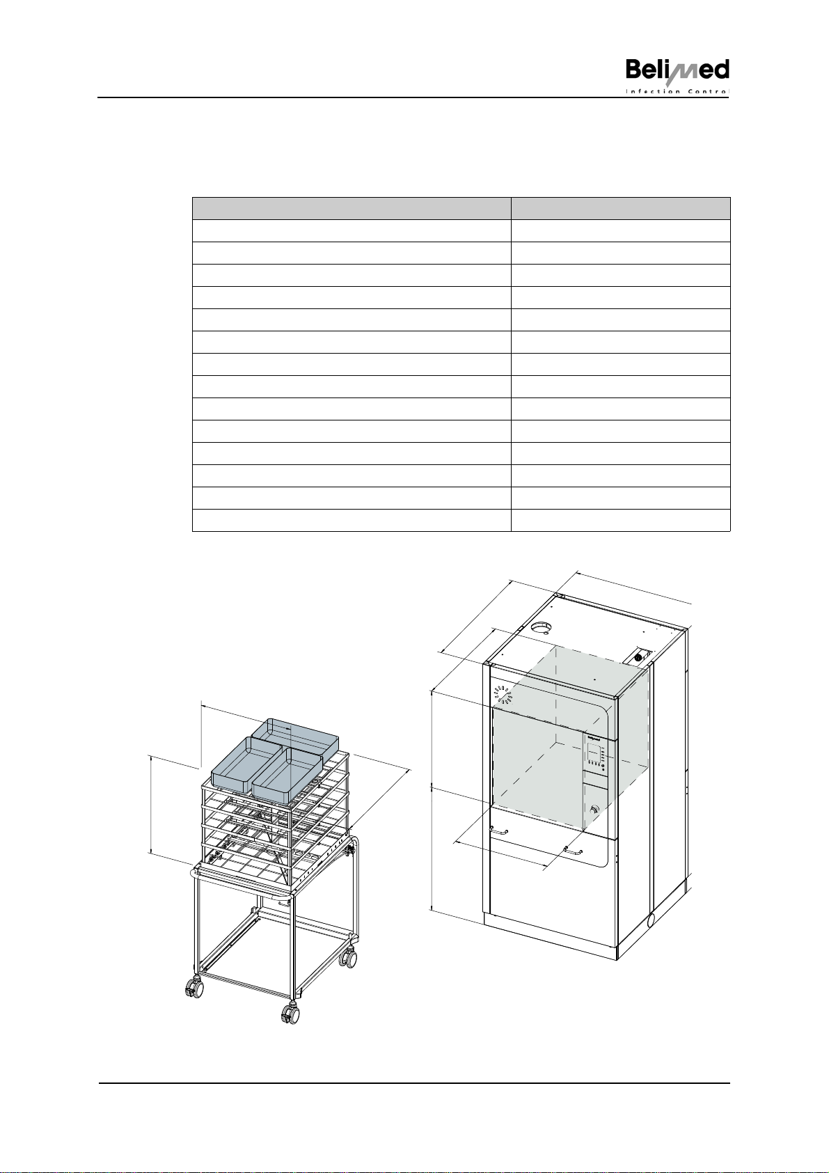
3.1 Machine dimensions
Dimension Measurement
Height 1840 mm
Width 900 mm
Depth 940 mm
Height of base 100 mm
Loading height 870 mm
Clearance height of washing chamber 690 mm
Clearance width of washing chamber 630 mm
Clearance depth of washing chamber 800 mm
Height of rack 670 mm
Width of rack 610 mm
Depth of rack 750 mm
Unloaded weight 310 kg
Total weight 380 kg
Washing chamber volume, min./max. 310 / 350 L
Fig
690mm870mm
800mm
940mm
900mm
630mm
100mm
max. 670mm
610mm
750mm

12/177 WD 290
10521 © Belimed
Machine specifications
3.2 Machine dimensions with condenser or PW tank (optional)
Dimension Measurement
Height 2210 mm
Width 900 mm
Depth 940 mm
Height of base 100 mm
Loading height 870 mm
Clearance height of washing chamber 690 mm
Clearance width of washing chamber 630 mm
Clearance depth of washing chamber 800 mm
Height of rack 670 mm
Width of rack 610 mm
Depth of rack 750 mm
Unloaded weight 453 kg
Total weight 593 kg
Washing chamber volume, min./max. 310 / 350 L
Fig 494
690mm870mm
800mm
630mm
100mm
2210 mm
940mm
900mm
max. 670mm
610mm
750mm

Machine specifications
WD 290 13/177
© Belimed 10521
3.3 Optional additional components
3.3.1 Options (only available ex-factory)
• Steam heating for washing chamber and dryer
• Switchable between steam operation and electric operation (washing cham-
ber only)
• Independent process data monitoring system IPD
• Conductivity monitoring system
• Two additional outputs
•Rackdrive
• Docking device for SISO
• Docking device for Rotary (fully automated)
• Wash arm rotation control
3.3.2 Options that can be upgraded in the field
• Dosing pumps with empty-level indicators (up to 5 units)
• Pre-shutoff valve activation
• PW tank, exhaust air condenser
• Sterile-filter monitoring function
(Dosers (up to 5 units))
• Empty-level monitoring system for dosage media, small / large
• Flow monitoring system for dosage media (up to 4 units)
• Drainage pump
• Built-in printer
• Barcode scanner
• Ethernet COM server
• Tabletop printer
•Floorpan
• Y-piece for dual IPD pressure sensor
3.3.3 Paneling
• Paneling for condenser or PW tank
• Side paneling
• Intermediate paneling
• Base paneling

14/177 WD 290
10521 © Belimed
Machine specifications
3.3.4 Further accessories
•Racks
– Single- or multi-level rack (1 level, 2 levels, 3 levels, 4 levels)
– Nozzle rack
– Shoe rack
– Anesthesia material rack
–ENTrack
–MISrack
• Screens and inserts
– Needle inserts
– Screen cover
– Special inserts
– Standard sieve trays
– Luer-Lock connector sets
– OR shoe inserts
– Attachment clamps
– Partition frame
• Paper rolls for built-in printer
• Paper rolls for tabletop printer
• Ink ribbon for tabletop printer

Machine specifications
WD 290 15/177
© Belimed 10521
3.4 Technical data
*see sep. manual
Performance characteristics / components Data/performance/specifica-
tions
Nominal delivery rate (delivery height) of circulation pump 900 L/min (2.5 m)
Effective delivery rate (delivery height) of circulation pump Depends on load and
water temperature
Power rating of circulation pump 2.2 kW
Material of pump impeller Chromium steel 1.4301
Electrical heating capacity of washing chamber (380-400V) 22.5 kW
Electrical heating capacity of washing chamber (200-220V) 18.0 kW
Overheating protection for washing chamber heating system Safety temperature limiter
Steam heating capacity of washing chamber (450 kPa) 30 kW
Length of wash arm in the machine 600 mm
Drainage valve Chromium steel 1.4301
Max. delivery height of drainage pump 10 m
Dosing pumps 24 VAC / 10L/h
Material of peristaltic tube Pharmed
Max. suction height (at 1mPa s; 20°C) 1.7 m
Max. delivery height (at 1mPa s; 20°C) 2 m
Number of dosing pumps in standard model 3 units
Number of flow meters in standard model 3 units
Electric heating capacity of dryer 10.5 kW
Overheating protection for dryer Safety temperature limiter
Steam heating capacity of dryer (300 kPa) 16 kW
Delivery rate of dryer fan 650 m3/h
Power rating of dryer fan 2.4 kW
Heat radiation (standing free with full paneling) 500 (+/-200) W
Noise emission (during washing) 65 dB (A)
Noise emission (short-term, during drying) 72 dB (A)
Dead water volume 0.1-0.2 L
Washing chamber seal Silicone
Operation of the washing chamber door Automatic
Material of washing chamber 1.4404
Material of paneling and frame 1.4301
Thickness of washing chamber wall 1.5 mm
Washing chamber door material Glass
Options Data/performance/specifications
PW tank heating capacity* 9000 W
Overheating protection for PW tank heater Glass fuse/ safety temperature
limiter

16/177 WD 290
10521 © Belimed
Machine specifications
3.5 Surrounding conditions
3.5.1 Storage
CAUTION!
Avoid direct sunlight and one-sided air currents (close to window).
3.5.2 Transport
3.5.3 Location
CAUTION!
Avoid direct sunlight and one-sided air currents (close to window).
Criterion Requirement
Ambient or room temperature 0°C - +50°C
Relative humidity, non-condensing 10 - 90%
Max. storage time 1 year
Atmosphere Non-corrosive
Criterion Requirement
Room temperature -25°C - +55°C
Room temperature, short-term (24 h) -25°C - +70°C
Relative humidity, non-condensing 10 - 90%
Max. duration of transport 1 month
Criterion Requirement
Max. altitude of setup location 1600 m above sea level
Max. relative humidity 80%
Ambient or room temperature +5°C - +30°C
Degree of contamination 2 (P2)
Space required per machine 5 m2
Min. load capacity of floor 500 kg/m2
Floor characteristics fire proof
Minimum distance between machines 50 mm
Evenness of floor - difference in levels < 10 mm

Machine specifications
WD 290 17/177
© Belimed 10521
3.6 Connection modules
3.6.1 General electrical power supply conditions
General electrical power supply conditions required for the machines to operate
fault-free.
CAUTION!
Maximum permissible mains voltage fluctuation +/- 10%.
Maximum permissible frequency tolerance +/- 1Hz.
3.6.2 Electrical connections
Voltage Frequency
3N 380-400 V ~ 50 Hz
3N 380-400 V ~ 60 Hz
208 V 3 ~ 60 Hz
200-220 V 3 ~ 60 Hz
200-220 V 3 ~ 50 Hz
Voltage 3N 380-415 V ~
50 Hz
3N 380-415 V ~
60 Hz
208 V 3 ~
60 Hz
200-220 V 3 ~
60 Hz
200-220 V 3 ~
50 Hz
480 V 3 ~
60 Hz
Electrically heat-
ed
Washing cham-
ber;
Dryer;
PW tank "locked"
Power rating 25 kW 25 kW 20 kW 21 kW 21 kW 27 kW
Fuse 40 A 40 A 50 A 60 A 60 A 40 A
Steam heated
Washing chamber
Electrically heat-
ed
Dryer; PW tank
"locked"
Power rating 13 kW 13 kW 13 kW 13 kW 13 kW 13 kW
Fuse 25 A 25 A 40 A 40 A 40 A 30 A
Steam heated
Washing cham-
ber;
Dryer
Power rating 3.5 kW 3.5 kW 3.5 kW 3.5 kW 3.5 kW 3.5 kW
Fuse 16 A 16 A 15 A 16 A 16 A 20 A

18/177 WD 290
10521 © Belimed
Machine specifications
3.6.3 Water connections
Cold water (CW) Min. temperature
Max. temperature
Water hardness
Salt content
Chloride content
pH
Water pressure (absolute)
Min. volume flow
Connection thread on building side
°C
°C
mmol/L
°dH
°fH
mg/L
mg/L
kPa
L/min
inch
5
20
0.7 - 2.0
3.9 - 11.2
7 - 20
< 500
< 100
5 - 8
200 - 600
8
3/4"
Warm water (WW) Max. temperature
Water hardness
Salt content
Chloride content
pH
Water pressure (absolute)
Min. volume flow
Connection thread on building side
°C
mmol/L
°dH
°fH
mg/L
mg/L
kPa
L/min
inch
60
0.7 - 2.0
3.9 - 11.2
7 - 20
< 500
< 100
5 - 8
200 - 600
8
3/4" (250 µm)
Purified water (PW) Max. recommended conductivity
pH
Water hardness
Salt content
Phosphate
Silicate
Chloride content
Water pressure (absolute)
Min. volume flow
Connection thread on building side
S/cm
mmol/L
mg/L
mg/L
mg/L
mg/L
kPa
L/min
inch
5 - 15
5 - 8
0.02
< 10
< 0.5
< 1
< 2
200 - 600
8
3/4" (250 µm)
Waste water Max. temperature
pH
Connection
Max. short term discharge
°C
D/mm
L/min
95
5 - 12
55
150

Machine specifications
WD 290 19/177
© Belimed 10521
3.6.4 Steam
(a) = absolute
3.6.5 Exhaust air
3.6.6 RS232, RS485 … interfaces
Only devices (e.g. barcode reader) and accessories which conform to the re-
quirements of IEC 60950-1 or IEC 61010-1 are allowed to be connected to the
existing interfaces (RS232, RS485 …).
Heating steam Steam pressure (a)
Max. boiling temperature (a)
Design capacity at 600 kPa (160°C)
Connection thread (flat-sealing)
kPa
°C
kg/h
inch
350 - 450
160
50
1/2" external
thread
Water heating Mass flow of saturated steam
Consumption / cycle at 300 kPa (a) kg/min
kg 0.8
12 - 16
Dryer Mass flow of saturated steam
Consumption / cycle for 10 min
Drying at 300 kPa
kg/min
kg 0.45
4.5
Exhaust air connection Connecting piece on machine mm D 114.5
I. Exhaust air system
connected directly to
outdoor surroundings
(not recommended)
Do not merge the exhaust
air systems of several WDs
Max. length of exhaust air pipe on building side
Exhaust air volume flow
Temperature average / short term max.
Rel. humidity average / short term max.
Maximum permissible pressure drop in exhaust
air pipe
m
m3/h
°C
%
Pa
5
250 - 350
70 / 90
80 / 100
350
II. Connection without
condenser to building ex-
haust air system with fan
Volume flow of building exhaust air system
Temperature average / short term max.
Rel. humidity average / short term max.
m3/h
°C
%
250 - 350
70 / 90
80 / 100
III. Connection with con-
denser to building exhaust
air system with fan
Volume flow of building exhaust air system
Temperature average / short term max.
Rel. humidity average / short term max.
Condenser power rating
Volume of condensed water
(only applies to thermal disinfection; A03000,
93°C; 12 minutes drying at 120°C)
m3/h
°C
%
kW
mL
250 - 350
70 / 90
< 70 / 100
2.7
approx. 100mL
20/177 WD 290
10521 © Belimed
Machine specifications
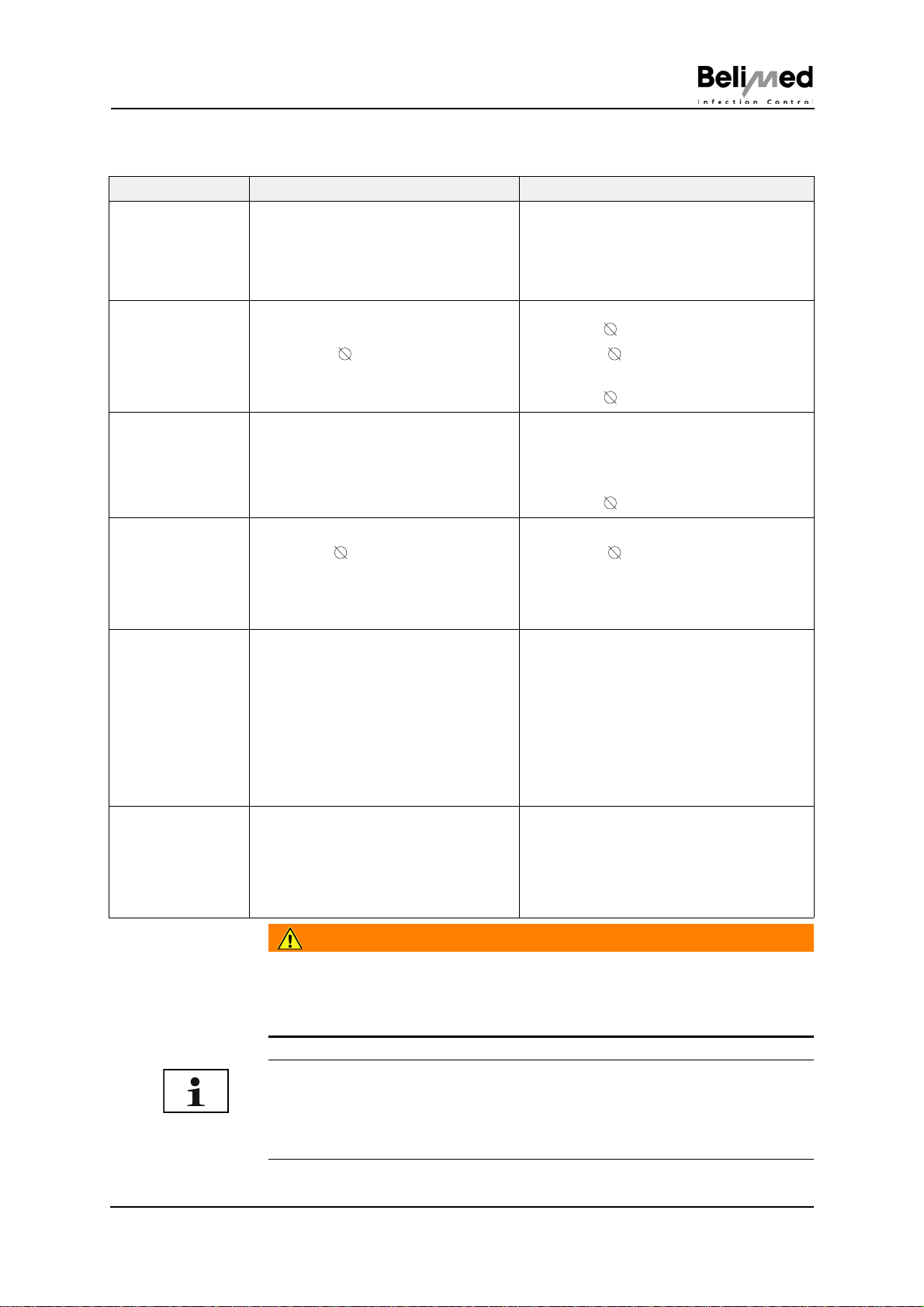
3.6.7 Connection requirements for installation
WARNING!
Maximum operating pressure of steam connection 700 kPa (a)! An excess-
pressure protection device at the steam connection site with
700 kPa (a) response pressure must be provided in the building. Only use
certified armatures!
Building Machine
Water
Cold
Warm
PW
• Shut-off valve, 3/4" • Armored tube, 2 m
• Fine filter, 3/4" / mesh width 250m
• Free flow passage
Drain • Floor drain with siphon
• Drainage nozzle
external = 55 mm
• Odor seal
• T-piece for condensate drain
internal = 20 mm
external = 26 mm
• Drainage tube, EPDM
internal = 55 mm
Drainage pump • Drainage pipe with siphon • Delivery height, 100 L/min (1 m), up to
10 m
(optional)
• Drainage tube
internal = 19 mm
Exhaust air • Water-resistant exhaust air pipe
internal = 115 mm
• Motor-driven exhaust air flap
• Draught interrupter for exhaust air
channel
• Drainage pipe
external = 114.5 mm
• Condensate drain
• Exhaust air flap with false-air opening
Electrical con-
nection Electricalpowersupplyconditionssee
Chap. 3.6.2 "Electrical connections"
Installation category (CAT II)
Disconnection of the mains power
fromthemachine usingmainswitchor
mains plug is easily accessible.
• Harmonized cable, 400V 5 x 6 mm2or
5 x 4 mm2
Cable length 1 m
• Harmonized cable, 200-220V
Cable length 1 m, 4 x 10 mm2or
Cable length 1 m, 4 x 6 mm2
• Connection terminal, 208V / 480V
Terminal box
Steam connec-
tion • Two shut-off valves, 1/2"
• Dirt separator, 1/2"
• Insulated armored tube
2 x 3.5 m
• Manometer recommended
• One 2/2 solenoid valve, 1/2", 24 V AC
• G1/2" connection, 60° inside taper
• Outlet, G1/2", 60° inside taper
• Two 1/2" condensate separators
• Two non-return valves
NOTICE
Compressed air connection does not have to be provided.
Steam supply and discharge pipes are flushed via bypass.
Keep electrical supply and steam supply separate.
Other manuals for WD 290
3
Table of contents
Other BELIMED Washer manuals


Popular Washer manuals by other brands


Samsung
Samsung WA65F5S2 user manual

Indesit
Indesit BWSD 71252 Instructions for use

Siemens
Siemens WM16XEH1IL User manual and installation instructions

Maytag
Maytag BRAVOS XL Use and care guide

Whirlpool
Whirlpool FULL ELECTRONIC WASHING MACHINE user guide

Siemens
Siemens WM14LPH0ES User manual and installation instructions


