manuals.online logo
Brands
  1. Home
  2. •
  3. Brands
  4. •
  5. Belimo
  6. •
  7. Controllers
  8. •
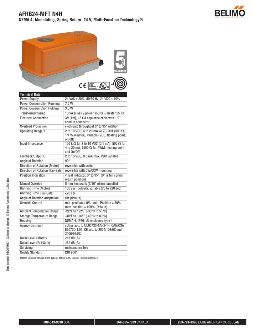
  9. Belimo FGVL Series User manual

Belimo FGVL Series User manual

1
®
QUICK MOUNT VISUAL INSTRUCTION MANUAL
FGVL Linkage with EV Series Actuators
1/4” - 28 UNF
1/4”- 32 UNEF
3/8”- 24 UNF
7/16“ - 20 UNF
1/2“ - 20 UNF
M8 x 1.25
M8 x 1
M10
M12 x 1.25
M16 x 2
M16 x 1. 5
optional
12b
3
4
Optional
Siebe VB9.. page 4
Johnson Controls VG2231 VN,
VG2231 WN
page 4
20 Nm
19 mm
32 mm
8 mm
12
1
2
2a STYLE B
STYLE A
B
A
View the installation video for FGVL on Belimo's YouTube channel:
https://youtu.be/fqs8XfRPyQw
71824-00001.B05/16 - Subject to change. © Belimo Aircontrols (USA), Inc.
2
®
QUICK MOUNT VISUAL INSTRUCTION MANUAL
FGVL Linkage with EV Series Actuators
6
7
8
5
75 Nm
19 mm
5 Nm
23
4
1
2
1
Bring Level
Tighten
Evenly
ABS
Must be
Flush with
Bonnet
3
®
QUICK MOUNT VISUAL INSTRUCTION MANUAL
FGVL Linkage with EV Series Actuators
912
10
5 Nm
5 mm
2
1
1
2
Must Snap Together
Tighten Evenly
13
11
1
1
2
Push Adaption for
3 Seconds with Power
STOP
Optional Lock and Manual Override
2
3720°
4
®
1
2
SIEBE
SIEBE DN
min. / max. Temp.
VB9 65 / 300 2 ... 150 °C
1
2
JOHNSON CONTROL
JOHNSON
CONTROLS
DN
min. / max. Temp.
VG2231 VN 65 / 100 2 ... 150 °C
VG2231 WN 65 / 150 2 ... 150 °C
1
2
Isolate Valve
First
1
2
QUICK MOUNT VISUAL INSTRUCTION MANUAL
FGVL Linkage with EV Series Actuators
Optional
5
®
QUICK MOUNT VISUAL INSTRUCTION MANUAL
FGVL Linkage with EV Series Actuators
WIRING DIAGRAMS
BLK
Black
Negro
Noir
Preto
RED
Red
Rojo
Rouge
Vermelho
WHT
White
Blanco
Blanc
Branco
PNK
Pink
Rosado
Rosa
Cor-de ros
ORG
Orange
Anaranjado
Orange
Alaranjado
BLU
Blue
Azul
Bleu
Azul
BRN
Brown
Marron
Brun
Marrom
Non-Spring Return Actuator with -3 Non-Spring Return Actuator with -SR
24 VAC Transformer
Blk (1) Common
Red (2) +
Wht (3) +
Line
Volts
2 3 18
Blk (1) Common
Red (2) +
Wht (3) +
Line
Volts
24 VAC Transformer
2 3 18
Blk (1) Common
Red (2) + Hot
Wht (3) Y1Input, 2 to 10 V
Org (5) U Output, 2 to 10 V
(–)
(+)
Line
Volts
24 VAC Transformer
Control Signal
VDC/mA
318
7
Ω500Ω
1/4 W
On/Off Floating Point VDC / 4 to 20 mA
100 to 240 VAC
Blu (1) Common
Brn (2) +
Wht (3) +
N L1
H L2
–
Line
Hot
A
2
Blk (1) Common
Brn (2) +
Wht (3) +
A
2
Line N L1
Hot H L2
100 to 240 VAC
Signal
Direction
On/Off Floating Point Selector Switches
Com
Line
Volts
Hot
Controller
24 VAC Transformer (AC only)
–
Blk (1) Common
Red (2) + Hot
Wht (3)
Y
1
Input
2
24 VAC Transformer (AC only)
Line
Volts
Hot
Controller
Com
–
Blk (1) Common
Red (2) + Hot
Wht (3)
Y
1
Input
2
Triac Sink Triac Source
Non-Spring Return Actuator with MFT
Blk (1) Common
Red (2) Hot
Wht (3) Y Input
Org (5) U Output
Line
Volts
24 VAC Transformer
2 to 10 VDC
Feedback Signal (+)
(–)
318
Line
Volts
(–)
(+)
24 VAC Transformer
Blk (1) – Common
Red (2) + Hot
Wht (3) Y1Input
Org (5) U Output 2 to 10 V
AB AB
Direction of rotation switch
A
B
Feedback Signal
2 to 10 VDC
210 18
1818
8
912
Notes:
On/Off Floating Point
Blk (1) Common
Red (2) + Hot
Wht (3) Y1Input, 2 to 10 V
Org (5) U Output, 2 to 10 V
(–)
(+)
Line
Volts
24 VAC Transformer
Control Signal
VDC/mA
318
7
Ω500Ω
1/4 W
Functions
0%
50%
100%
Control mode acc. to Y
Min
Mid
Max
Normal
abc
500
Blk (1) Common
Red (2) + Hot
Org (5)
Wht (3) Y1Input, 2 to 10 V
(–)
(+)
Line
Volts
24 VAC Transformer (AC Only)
B
C
A
1/4 W
VDC/mA
Control Signal
18
7
Ω
Ω
VDC / 4 to 20 mA Override Control Min, Mid, Max Postions
Meets cULus requirements without the need of an
electrical ground connection
AActuators with appliance cables are numbered.
2Actuators may be connected in parallel. Power
consumption and input impedance must be observed.
3Actuators may also be powered by 24 VDC.
5Only connect common to neg. (-) leg of control circuits.
7A 500 resistor converts the 4 to 20 mA control signal
to 2 to 10 VDC.
8Control signal may be pulsed from either the Hot
(Source) or Common (Sink) 24 VAC line.
9
Contact closures A & B also can be triacs. A & B
should both be closed for the triac source and open
for triac sink.
10
For triac sink the Common connection from the actuator
must be connected to the Hot connection of the
controller. Position feedback cannot be used with a triac
sink controller. The actuator internal common reference
is not compatible.
1212
IN4004 or IN4007 diode. (IN4007 supplied, Belimo Part
number 40155)
18 Actuators with plenum rated cable do not have numbers
on wires; use color codes instead.
6
®
QUICK MOUNT VISUAL INSTRUCTION MANUAL
FGVL Linkage with AVK Series Actuators
1/4” - 28 UNF
1/4”- 32 UNEF
3/8”- 24 UNF
7/16“ - 20 UNF
1/2“ - 20 UNF
M8 x 1.25
M8 x 1
M10
M12 x 1.25
M16 x 2
M16 x 1. 5
optional
12b
3
4
Optional
Siebe VB9.. page 4
Johnson Controls VG2231 VN,
VG2231 WN
page 4
20 Nm
19 mm
32 mm
8 mm
12
1
2
2a STYLE B
STYLE A
B
A
7
®
QUICK MOUNT VISUAL INSTRUCTION MANUAL
FGVL Linkage with AVK Series Actuators
6
7
8
5
75 Nm
19 mm
5 Nm
23
4
1
2
1
Bring Level
Tighten
Evenly
ABS
Must be
Flush with
Bonnet
8
®
QUICK MOUNT VISUAL INSTRUCTION MANUAL
FGVL Linkage with AVK Series Actuators
912
11
10
5 Nm
1
5 mm
2
1
1
2
M
Optional Manual Override
3
Must Snap Together
Tighten Evenly
13
Push Adaption for
3 Seconds with Power
STOP
2
3720°
9
®
1
2
SIEBE
SIEBE DN
min. / max. Temp.
VB9 65 / 300 2 ... 150 °C
1
2
JOHNSON CONTROL
JOHNSON
CONTROLS
DN
min. / max. Temp.
VG2231 VN 65 / 100 2 ... 150 °C
VG2231 WN 65 / 150 2 ... 150 °C
1
2
Isolate Valve
First
1
2
QUICK MOUNT VISUAL INSTRUCTION MANUAL
FGVL Linkage with AVK Series Actuators
Optional
10
®
WIRING DIAGRAMS
QUICK MOUNT VISUAL INSTRUCTION MANUAL
FGVL Linkage with AVK Series Actuators
BLK
Black
Negro
Noir
Preto
RED
Red
Rojo
Rouge
Vermelho
WHT
White
Blanco
Blanc
Branco
PNK
Pink
Rosado
Rosa
Cor-de ros
ORG
Orange
Anaranjado
Orange
Alaranjado
BLU
Blue
Azul
Bleu
Azul
BRN
Brown
Marron
Brun
Marrom
Electronic Fail-Safe Actuator with -3
24 VAC Transformer
Line
V
olts
–
Blk (1) Common
Red (2) + Hot
Wht (3) +
Y
1
Input
Pnk (4)
2 3 18
Blk (1)
Red (2)
Wht (3)
Pnk (4)
Common
Hot +
Y1Input
Y2Input
2
Line
Volts
24 VAC Transformer
8
18
9
On/Off Floating Point
Blu (1)
Brn (2) +
Wht (3) +
Wht (4)
100 to 240 VAC
N L1
H L2
Line
Hot
A
2
A
Line N L1
Hot H L2
100 to 240 VAC
Blu (1)
Brn (2) +
Wht (3) +
Wht (4) +
2
50%
Signal
Direction
Fail
Postion
On/Off Floating Point Selector Switches
ComHot
Controller
Line
Volts
24 VAC Transformer
Blk (1) Common
Red (2) Hot
Wht (3) Y1Input
Pnk (4) Y2Input
+
510 18
ComHot
Controller
Line
Volts
24 VAC Transformer
Blk (1) Common
Red (2) Hot
Wht (3) Y1Input
Pnk (4) Y2Input
+
18
Blk (1) Common
Red (2) Hot
Wht (3) Y1Input
Pnk (4) Y2Input
ComHot
Controller
Line
Volts
24 VAC Transformer Line
Volts
24 VAC Transformer
+
10 18
Triac Sink Triac Source Triac Sink with Separate Transformer
Electronic Fail-Safe Actuator with MFT
Blk (1) Common
Red (2) Hot
Wht (3) Y Input
Org (5) U Output
Line
Volts
24 VAC Transformer
2 to 10 VDC
Feedback Signal (+)
(–)
318
Line
Volts
(–)
(+)
24 VAC Transformer
Blk (1) – Common
Red (2) + Hot
Wht (3) Y1Input
Org (5) U Output 2 to 10 V
AB AB
Direction of rotation switch
A
B
Feedback Signal
2 to 10 VDC
210 18
1818
8
912
Notes:
On/Off Floating Point
Blk (1) Common
Red (2) + Hot
Wht (3) Y1Input, 2 to 10 V
Org (5) U Output, 2 to 10 V
(–)
(+)
Line
Volts
24 VAC Transformer
Control Signal
VDC/mA
318
7
Ω500Ω
1/4 W
Functions
0%
50%
100%
Control mode acc. to Y
Min
Mid
Max
Normal
abc
500
Blk (1) Common
Red (2) + Hot
Org (5)
Wht (3) Y1Input, 2 to 10 V
(–)
(+)
Line
Volts
24 VAC Transformer (AC Only)
B
C
A
1/4 W
VDC/mA
Control Signal
18
7
Ω
Ω
VDC / 4 to 20 mA Override Control Min, Mid, Max Postions
Meets cULus requirements without the need of an
electrical ground connection
AActuators with appliance cables are numbered.
2Actuators may be connected in parallel. Power
consumption and input impedance must be observed.
3Actuators may also be powered by 24 VDC.
5Only connect common to neg. (-) leg of control circuits.
7A 500 resistor converts the 4 to 20 mA control signal
to 2 to 10 VDC.
8Control signal may be pulsed from either the Hot
(Source) or Common (Sink) 24 VAC line.
9
Contact closures A & B also can be triacs. A & B
should both be closed for the triac source and open
for triac sink.
10
For triac sink the Common connection from the actuator
must be connected to the Hot connection of the
controller. Position feedback cannot be used with a triac
sink controller. The actuator internal common reference
is not compatible.
1212
IN4004 or IN4007 diode. (IN4007 supplied, Belimo Part
number 40155)
18 Actuators with plenum rated cable do not have numbers
on wires; use color codes instead.
11
®
QUICK MOUNT VISUAL INSTRUCTION MANUAL
FGVL Linkage with RV Series Actuators
1/4” - 28 UNF
1/4”- 32 UNEF
3/8”- 24 UNF
7/16“ - 20 UNF
1/2“ - 20 UNF
M8 x 1.25
M8 x 1
M10
M12 x 1.25
M16 x 2
M16 x 1. 5
optional
12b
3
4
Optional
Siebe VB9.. page 4
Johnson Controls VG2231 VN,
VG2231 WN
page 4
20 Nm
19 mm
32 mm
8 mm
12
1
2
2a STYLE B
STYLE A
B
A
12
®
QUICK MOUNT VISUAL INSTRUCTION MANUAL
FGVL Linkage with RV Series Actuators
6
7
8
5
75 Nm
19 mm
5 Nm
23
4
1
2
1
Bring Level
Tighten
Evenly
ABS
Must be
Flush with
Bonnet
13
®
QUICK MOUNT VISUAL INSTRUCTION MANUAL
FGVL Linkage with RV Series Actuators
912
10
5 Nm
5 mm
2
1
1
2
Must Snap Together
Tighten Evenly
13
11
1
1
2
Push Adaption for
3 Seconds with Power
STOP
2
3720°
Optional Lock and Manual Override
14
®
1
2
SIEBE
SIEBE DN
min. / max. Temp.
VB9 65 / 300 2 ... 150 °C
1
2
JOHNSON CONTROL
JOHNSON
CONTROLS
DN
min. / max. Temp.
VG2231 VN 65 / 100 2 ... 150 °C
VG2231 WN 65 / 150 2 ... 150 °C
1
2
Isolate Valve
First
1
2
QUICK MOUNT VISUAL INSTRUCTION MANUAL
FGVL Linkage with RV Series Actuators
Optional
15
®
QUICK MOUNT VISUAL INSTRUCTION MANUAL
FGVL Linkage with RV Series Actuators
WIRING DIAGRAMS
BLK
Black
Negro
Noir
Preto
RED
Red
Rojo
Rouge
Vermelho
WHT
White
Blanco
Blanc
Branco
PNK
Pink
Rosado
Rosa
Cor-de ros
ORG
Orange
Anaranjado
Orange
Alaranjado
BLU
Blue
Azul
Bleu
Azul
BRN
Brown
Marron
Brun
Marrom
Non-Spring Return Actuator with -3
Line
Volts
24 VAC Transformer
–
Blk (1) Common
Red (2) + Hot
Wht (3)
Y
1
Input
210 18
8
12
Line
V
olts
24 VAC Transformer
Blk (1) Common
Red (2) Hot +
Wht (3) Y1Input
AB AB
Direction of rotation switch
A
B
210 18
1818
8
912
Signal
Direction
On/Off Floating Point Selector Switches
Non-Spring Return Actuator with MFT
Blk (1) Common
Red (2) Hot
Wht (3) Y Input
Org (5) U Output
Line
Volts
24 VAC Transformer
2 to 10 VDC
Feedback Signal (+)
(–)
318
Line
Volts
(–)
(+)
24 VAC Transformer
Blk (1) – Common
Red (2) + Hot
Wht (3) Y1Input
Org (5) U Output 2 to 10 V
AB AB
Direction of rotation switch
A
B
Feedback Signal
2 to 10 VDC
210 18
1818
8
912
Notes:
On/Off Floating Point
Blk (1) Common
Red (2) + Hot
Wht (3) Y1Input, 2 to 10 V
Org (5) U Output, 2 to 10 V
(–)
(+)
Line
Volts
24 VAC Transformer
Control Signal
VDC/mA
318
7
Ω500Ω
1/4 W
Functions
0%
50%
100%
Control mode acc. to Y
Min
Mid
Max
Normal
abc
500
Blk (1) Common
Red (2) + Hot
Org (5)
Wht (3) Y1Input, 2 to 10 V
(–)
(+)
Line
Volts
24 VAC Transformer (AC Only)
B
C
A
1/4 W
VDC/mA
Control Signal
18
7
Ω
Ω
VDC / 4 to 20 mA Override Control Min, Mid, Max Postions
Meets cULus requirements without the need of an
electrical ground connection
AActuators with appliance cables are numbered.
2Actuators may be connected in parallel. Power
consumption and input impedance must be observed.
3Actuators may also be powered by 24 VDC.
5Only connect common to neg. (-) leg of control circuits.
7A 500 resistor converts the 4 to 20 mA control signal
to 2 to 10 VDC.
8Control signal may be pulsed from either the Hot
(Source) or Common (Sink) 24 VAC line.
9
Contact closures A & B also can be triacs. A & B
should both be closed for the triac source and open
for triac sink.
10
For triac sink the Common connection from the actuator
must be connected to the Hot connection of the
controller. Position feedback cannot be used with a triac
sink controller. The actuator internal common reference
is not compatible.
1212
IN4004 or IN4007 diode. (IN4007 supplied, Belimo Part
number 40155)
18 Actuators with plenum rated cable do not have numbers
on wires; use color codes instead.
®
Subject to change. © Belimo Aircontrols (USA), Inc.
Belimo Americas
USA, Latin America, and the Caribbean: www.belimo.us
Canada: www.belimo.ca
Brazil: www.belimo.com.br
Belimo Worldwide: www.belimo.com

Other Belimo Controllers manuals

Belimo GKX24-MFT-X1 User manual

Belimo

Belimo GKX24-MFT-X1 User manual

Belimo AF24-SR US Parts list manual

Belimo

Belimo AF24-SR US Parts list manual

Belimo NMB24-SR User manual

Belimo

Belimo NMB24-SR User manual

Belimo AFB Series User manual

Belimo

Belimo AFB Series User manual

Belimo AFX24LON User manual

Belimo

Belimo AFX24LON User manual

Belimo SY4 Series User manual

Belimo

Belimo SY4 Series User manual

Belimo LF24-SR-E US User manual

Belimo

Belimo LF24-SR-E US User manual

Belimo NM24A-MOD Instruction Manual

Belimo

Belimo NM24A-MOD Instruction Manual

Belimo LonWorks NMX24-LON User manual

Belimo

Belimo LonWorks NMX24-LON User manual

Belimo NMV-D3-RE2-SET User manual

Belimo

Belimo NMV-D3-RE2-SET User manual

Belimo HR series User manual

Belimo

Belimo HR series User manual

Belimo LMB24-MFT User manual

Belimo

Belimo LMB24-MFT User manual

Belimo SY 3-T Series User manual

Belimo

Belimo SY 3-T Series User manual

Belimo AF Series User manual

Belimo

Belimo AF Series User manual

Belimo FSNF230 US User manual

Belimo

Belimo FSNF230 US User manual

Belimo LRB24-SR-T Manual

Belimo

Belimo LRB24-SR-T Manual

Belimo EFB Series User manual

Belimo

Belimo EFB Series User manual

Belimo PR User manual

Belimo

Belimo PR User manual

Belimo FS Series Use and care manual

Belimo

Belimo FS Series Use and care manual

Belimo LRB24-MFT User manual

Belimo

Belimo LRB24-MFT User manual

Belimo LRQ24A User manual

Belimo

Belimo LRQ24A User manual

Belimo LMQB24-1 User manual

Belimo

Belimo LMQB24-1 User manual

Belimo PRCA-S2-T Instruction Manual

Belimo

Belimo PRCA-S2-T Instruction Manual

Belimo NF24A User manual

Belimo

Belimo NF24A User manual

Popular Controllers manuals by other brands

i2Systems Lightlink LL-105-R Setup guide

i2Systems

i2Systems Lightlink LL-105-R Setup guide

Shinko PCA1 instruction manual

Shinko

Shinko PCA1 instruction manual

Chromalox IntelliTrace ITC 1 Installation & operation manual

Chromalox

Chromalox IntelliTrace ITC 1 Installation & operation manual

Eaton SVX9000 Series manual

Eaton

Eaton SVX9000 Series manual

Carel mboss Assembly procedure

Carel

Carel mboss Assembly procedure

DEXAPLAN SL 614 - 10-2006 manual

DEXAPLAN

DEXAPLAN SL 614 - 10-2006 manual

RBH Access Technologies UNC100 manual

RBH Access Technologies

RBH Access Technologies UNC100 manual

EngA DJM3 User's operation manual

EngA

EngA DJM3 User's operation manual

TAC Xenta 511 Installation instruction

TAC

TAC Xenta 511 Installation instruction

Ametek ZF1 SSR Series Instruction, Operation and Maintenance Manual

Ametek

Ametek ZF1 SSR Series Instruction, Operation and Maintenance Manual

Algo 8300 Installation/configuration

Algo

Algo 8300 Installation/configuration

UNV DMC8000 quick guide

UNV

UNV DMC8000 quick guide

Zmotion ZMC004WEA manual

Zmotion

Zmotion ZMC004WEA manual

Sentera STRA4 Mounting and operating instructions

Sentera

Sentera STRA4 Mounting and operating instructions

Panasonic FP0H Series user manual

Panasonic

Panasonic FP0H Series user manual

CAL Controls CAL 9500P Abridged user manual

CAL Controls

CAL Controls CAL 9500P Abridged user manual

Megasun MGS - CR manual

Megasun

Megasun MGS - CR manual

Irritrol KwikDial user guide

Irritrol

Irritrol KwikDial user guide

manuals.online logo
manuals.online logoBrands
  • About & Mission
  • Contact us
  • Privacy Policy
  • Terms and Conditions

Copyright 2025 Manuals.Online. All Rights Reserved.