manuals.online logo
Brands
  1. Home
  2. •
  3. Brands
  4. •
  5. Belimo
  6. •
  7. Controllers
  8. •
  9. Belimo CR24 Series User manual

Belimo CR24 Series User manual

Dimensions, installation, commissioning, service CR24-..
www.belimo.com 25
Product information S4-CR24-.. • en • v2.1 • 08.2006 • Subject to changes
1 2 3 4 5 6 7 8
1.5mm21.5mm2
2.5mm2AC 24V -
-
9
10
11
12
1
2
3
4
5
6
7
8
~
1 2 3 4 5 6 7 8
Cam
Left stop
1
2
3
1 2 3 4 5 6 7 8
1. Remove the housing cover.
2. Pull out slightly the wall of the housing to
release the pcb.
3. Remove the printed circuit board.
Rotary knob for setpoint adjustment
If the rotary knob has been removed proceed
as follows:
a. Insert the rotary knob approximately half
way and turn it clockwise as far as the stop.
b. Remove the knob and align it so that the
cam is flush with the left stop.
c. Insert the knob fully.
Dimensions [mm]
56
60
56
99
84
90
32
Mechanical installation
Electrical installation
Dimensions, installation, commissioning, service
CR24-..
26 www.belimo.com
Product information S4-CR24-.. • en • v2.1 • 08.2006 • Subject to changes
Power supply design / wire sizing
In addition to the actual wire sizing, attention must also be paid to the surrounding area and the
cable routing. Signal cables must not be laid in the vicinity of load cables, objects liable to cause
EMC interference etc. Paired or layer stranded cables improve immunity to interference.
24 V supply
Wire sizing and cabling
The wire sizing and installation of the AC 24 V supply, the fuse protection, and the cables are
dependent on the total operated load and local regulations.
Account must be taken of the following performance data, including starting currents:
– Wire sizing values for room temperature controllers: 3 VA per CR24-...
– Wire sizing values for control devices, VAV controllers, damper actuators, valves etc. can be
found in the latest data sheets and product information (www.belimo.com)
– Other devices to be operated with the AC 24 V supply
– Reserve capacity for subsequent expansion (if planned)
Digital input connections di1 / di2 / di3 The digital inputs of the CR24 controllers are connections with a low electrical load that can be
controlled by a common switching contact if necessary.
Example: Common thermostat for changeover function.
The maximum cable length depends on the number of CR24 controllers and the cross section
of the cable used or the maximum resistance of the cable and switching contact as well as the
quality of the environment.
No. of
CR24-...
Cable cross
section Cable length
10 0.75 mm2max. 250 m
20 0.75 mm2max. 200 m
20 1.00 mm2max. 250 m
25 0.75 mm2max. 170 m
25 1.00 mm2max. 220 m
25 1.50 mm2max. 250 m
30 0.75 mm2max. 140 m
30 1.00 mm2max. 190 m
30 1.50 mm2max. 250 m
40 0.75 mm2max. 100 m
40 1.0 mm2max. 140 m
40 1.50 mm2max. 210 m
50 0.75 mm2max. 80 m
50 1.00 mm2max. 110 m
50 1.50 mm2max. 170 m
If the number of CR24-.. controllers exceeds
that indicated in the table, the next higher
number of CR24-.. controllers should be taken
instead.
Example of a system with 13 CR24-B1 con-
trollers and a common C/O contact:
Use the table data for 20 CR24.. controllers to
design the cable:
20 x CR24-.. → 0.75 mm2 → 200 m.
Analog input connection ai1 The analog input ai1 is used to connect an external NTC 5 kΩ temperature sensor. The sensor
value is 5969 Ω at 21°C. A change of 50 Ω corresponds to approximately 0.2 K in this range.
The sensor cable constitutes a series resistance that must be added to the actual sensor value.
Assuming a cable length of 15 m (2 x 15 = 30 m), the resistance of one 0.75 mm2 Cu cable is
approximately 0.7 Ω, in other words negligible.
To prevent interference, however, the sensor cable should be a maximum of 20 m long.
Analog input connection ai2 The 0...10 V input (with the 10 kΩ pulldown resistor) can be used to connect an external 0...10 V
signal for a setpoint shift.
The current is calculated according to Ohm’s Law: I = U / R: 10 V / 10 kΩ = 1 mA.
Calculation: Maximum permissible voltage drop across the cable (V) divided by the current (1
mA) = cable impedance in Ω.
Note
This table does not apply to the design of the AC
24 V power supply cable.
The supply cable is determined by the total power
of all loads (see above).
Dimensions, installation, commissioning, service CR24-..
www.belimo.com 27
Product information S4-CR24-.. • en • v2.1 • 08.2006 • Subject to changes
Commissioning / Power on behaviour
Commissioning 1. Assemble the baseplate of the housing and connect the cables (see page 15).
2. Configure the DIP switches on the printed circuit board according to the required application.
3. Assemble the printed circuit board on the baseplate of the housing and then mount the
housing cover (see page 15).
4. Switch on the nominal voltage (AC 24 V).
5. Optional: start the test and simulation mode (see below).
When the voltage is applied, the system starts operating normally in AUTO mode (unless the
test and simulation mode is selected). The
active operating status is determined primarily by the configuration of the DIP switches and the
status of the inputs
Power on behaviour After power on of the voltage supply the output gets initialized as
follows:
– ao1 = 0 V
– ao2 = 0 V
– ao3 = closed (200 s)
Subsequently the controller switches automatically to the control mode.
Test and simulation mode
All controllers are supplied with two auxiliary programs for commissioning and servicing:
– Internal function test
– Control sequence simulation
Activating test and simulation mode The test and simulation mode of CR24-B.. controllers can be activated easily with the mode
switch on the operator panel. With CR24-A.. controllers, the housing cover must be removed
first.
To activate test mode
1. Set the mode switch to MAX
– The red LED (MAX status indication) lights up
2. Keep the mode switch pressed for ten seconds
– The internal function test is activated (see below)
To activate simulation mode
3. Press the mode switch again briefly (for approximately one second)
– The green LED (AUTO status indication) flashes
– Control sequence simulation is activated (see below)
Deactivating test and simulation mode The test and simulation mode can be deactivated either by pressing the mode switch again for
ten seconds or by interrupting the power supply. It is also deactivated automatically 15 minutes
after the last user action (auto-reset).
Internal function test
The internal function test tests the nominal voltage that is connected to the controller (AC 24 V),
in other words the complete electrical wiring system from the control cabinet to the controller.
The three LEDs (status indication) indicate the voltage level (see below) and states during the
test.
Nominal voltage (AC 24 V)
LED (status indication) Scenario A Scenario B Scenario C
MAX red flash flash permanently on
ECO orange flash flash permanently on
AUTO green permanently off flash permanently on
<20 V 20...22 V >22 V
Note
Case B and C do not need further attention. In
case A (<20 V) attation must be paid to the follow-
ing points:
– Quality of the wiring and connections
– Cable length/diameter and the transformer sizing.
Dimensions, installation, commissioning, service
CR24-..
28 www.belimo.com
Product information S4-CR24-.. • en • v2.1 • 08.2006 • Subject to changes
Control sequence simulation (CR24-B1, CR24-B2, CR24-B3)
CR24-B1, CR24-B2, CR24-B3 The connected actuators, and thus also the heating and cooling control sequences, can be
simulated independently of the room temperature in simulation mode.
This permits the air volume (min and max) to be tested in air systems or the maximum heating
and cooling capacity in water systems.
+3
–2
–1
+2
+1
W = X
–3
0
Y [V]
tS [°C]
10
2
0
ao1
ao2
ao1
XpH XpC
0
–3 +3
ao2
ao3
Potentiometer (setpoint adjustment)
for simulating the room temperature
Heating Cooling
CR24-B2E The simulation mode for the CR24-B2E is basically as described above.
Unlike water operated air heaters, electric air heaters are not allowed to be operated without a
flow. Simulations can be carried out on the CR24-.. at any time, even if the ventilation system is
not operating.
The two triac outputs are activated for a maximum of 15 seconds in simulation mode to prevent
overheating due to operation without ventilation. To activate these outputs again, the potentio-
meter must be reset via the “0” position to the heating range.
+3
–2
–1
+2
+1
W = X
–3
0
O
S
10
2
0
XpH XpC
0
–3 +3
out
3
out
1
II IIII
max. 15 s
Potentiometer (setpoint adjustment)
for simulating the room temperature
Notes
– The external control signals (di1, di2 and di3)
are suppressed while the simulation is active.
– The potentiometer changes during simulation
mode should be done slowly to avoid over-
shooting of the output values due to the system
depending adjuster damping.
– A-types (controllers without operation panel):
please do reset the potentiometer to the 0-posi-
tion after simulation to avoid setpoint deviations.
– Simulation mode is automatically deactivated 15
minutes after the last user action (auto-reset).

Other manuals for CR24 Series

2

This manual suits for next models

6

Other Belimo Controllers manuals

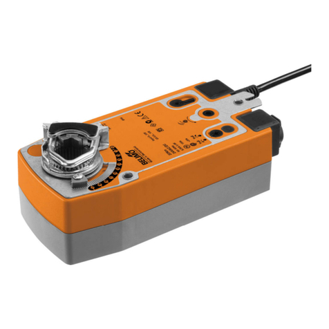
Belimo LMQB24-1 User manual

Belimo

Belimo LMQB24-1 User manual

Belimo FS Series Use and care manual

Belimo

Belimo FS Series Use and care manual

Belimo LF24 US User manual

Belimo

Belimo LF24 US User manual

Belimo TRANE TTF Series Guide

Belimo

Belimo TRANE TTF Series Guide

Belimo GMX24-3-X1 User manual

Belimo

Belimo GMX24-3-X1 User manual

Belimo SY4 Series User manual

Belimo

Belimo SY4 Series User manual

Belimo AM230-SR User manual

Belimo

Belimo AM230-SR User manual

Belimo ZSN-BF User manual

Belimo

Belimo ZSN-BF User manual

Belimo SRF230A-S2-5-O Instruction Manual

Belimo

Belimo SRF230A-S2-5-O Instruction Manual

Belimo SY 3-T Series User manual

Belimo

Belimo SY 3-T Series User manual

Belimo AFB Series User manual

Belimo

Belimo AFB Series User manual

Belimo AFX24LON User manual

Belimo

Belimo AFX24LON User manual

Belimo AF Series User manual

Belimo

Belimo AF Series User manual

Belimo VAV-Compact D3 User manual

Belimo

Belimo VAV-Compact D3 User manual

Belimo CMB24-3 User manual

Belimo

Belimo CMB24-3 User manual

Belimo NF24A-SR-S2 Instruction Manual

Belimo

Belimo NF24A-SR-S2 Instruction Manual

Belimo AMQB24-MFT User manual

Belimo

Belimo AMQB24-MFT User manual

Belimo NIMOFR C Series User manual

Belimo

Belimo NIMOFR C Series User manual

Belimo SY U24-SR Series Quick start guide

Belimo

Belimo SY U24-SR Series Quick start guide

Belimo NF24A-MOD Instruction Manual

Belimo

Belimo NF24A-MOD Instruction Manual

Belimo PKR Series User manual

Belimo

Belimo PKR Series User manual

Belimo AVK230A-3 User manual

Belimo

Belimo AVK230A-3 User manual

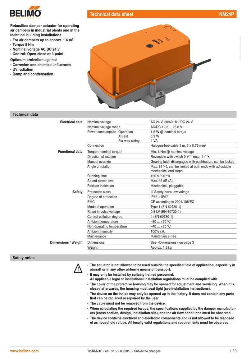
Belimo NM24P Instruction Manual

Belimo

Belimo NM24P Instruction Manual

Belimo AFRB24-MFT N4H User manual

Belimo

Belimo AFRB24-MFT N4H User manual

Popular Controllers manuals by other brands

Honeywell Excel 15 W7760A installation instructions

Honeywell

Honeywell Excel 15 W7760A installation instructions

Siko AG03 User information

Siko

Siko AG03 User information

Ltech LT-312RF quick start guide

Ltech

Ltech LT-312RF quick start guide

SunWare FOX-260 Li Installation

SunWare

SunWare FOX-260 Li Installation

PS Automation PSR-E-C Series operating instructions

PS Automation

PS Automation PSR-E-C Series operating instructions

Technibel Climatisation K70D043Z installation instructions

Technibel Climatisation

Technibel Climatisation K70D043Z installation instructions

Honeywell ML6420 Product data

Honeywell

Honeywell ML6420 Product data

GYS NOMAD POWER 12.24V manual

GYS

GYS NOMAD POWER 12.24V manual

Vacon 100 INDUSTRIAL user manual

Vacon

Vacon 100 INDUSTRIAL user manual

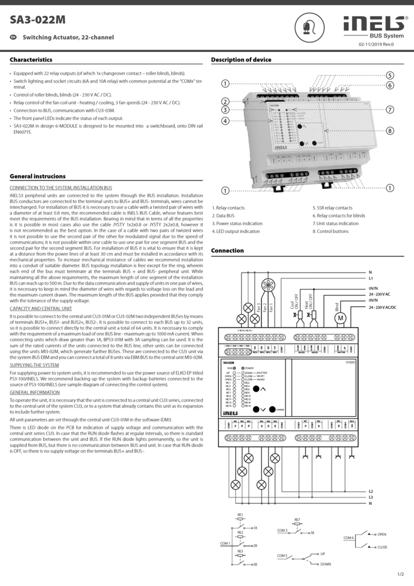
Elko iNels SA3-022M quick start guide

Elko

Elko iNels SA3-022M quick start guide

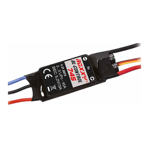
Multiplex ROXXY BL-Control 712 BEC operating instructions

Multiplex

Multiplex ROXXY BL-Control 712 BEC operating instructions

SEW-Eurodrive MOVI-PLC basic DHP11B-T0 manual

SEW-Eurodrive

SEW-Eurodrive MOVI-PLC basic DHP11B-T0 manual

Eaton ADS8 Series Instruction leaflet

Eaton

Eaton ADS8 Series Instruction leaflet

Elotech R 1140 operating manual

Elotech

Elotech R 1140 operating manual

Argus Cordex CXC How to connect

Argus

Argus Cordex CXC How to connect

CS-BATTERIES PRO-V4 CSX1206-025PV4 user manual

CS-BATTERIES

CS-BATTERIES PRO-V4 CSX1206-025PV4 user manual

Autonics SPR3 Series product manual

Autonics

Autonics SPR3 Series product manual

PEDROLLO 50066/415P user manual

PEDROLLO

PEDROLLO 50066/415P user manual

manuals.online logo
manuals.online logoBrands
  • About & Mission
  • Contact us
  • Privacy Policy
  • Terms and Conditions

Copyright 2025 Manuals.Online. All Rights Reserved.