Bell&Howell FILMSOUND 302 User manual

Disclaimer
This scanned document is provided as a courtesy. We make
no representation for its accuracy. It is for use by qualified
personnel only. There are high voltage and mechanical
hazards present in this equipment. Do not attempt repair
unless you are fully aware of the safety precautions to be
taken. Use this information at your own risk.
www.paulivester.com
SERVICE
INSTRUCTIONS
DESIGN
INDEX
CHART
Design
Number
Model
Letter
Parts
List
Code
Letter
Description
302
L
A
16
-mm
Filmosound
magnetic
and
optical
sound
projector,
120
-volt,
50-60
cycle,
oval
case
-mounted
speaker,
sapphire
shuttle
and
film
guide,
grey
wrinkle
finish.
302
M
B
Same
as
Design
302L,
except
grey
smooth
finish
and
loopsetter
(item
4-31)
added.
8302
A
C
Same
as
Design
302M,
except
made
in
Japan.
Most
notable
difference
in
amplifier
and
door
-mounted
speaker.
8302
AO
Same
as
Design
8302A,
except
with
oil
cup
lubrication
system
parts
(Parts
List
Fig.
5)
added.
8302
AP
Same
as
Design
8302A,
except
with
3
-wire
power
cord
8302
APO
(part
no.
32051)
added.
Same
as
Design
8302A,
except
with
3
-wire
power
cord
and
oil
cup
lubrication
system
parts
(Parts
List
Fig.
5)
added.
8302
AT
Same
as
Design
8302A,
except
tropicalized.
8302
ATO
Same
as
Design
8302AT,
except
with
oil
cup
lubrication
system
parts
(Parts
List
Fig.
5)
added.
8302
B
D
Same
as
Design
8302A,
except
220
-volt.
8302
BO
Same
as
Design
8302AO,
except
220
-volt.
8302
BP
Same
as
Design
8302AP,
except
220
-volt.
8302
BPO
Same
as
Design
8302APQ,
except
220
-volt.
8302
BT
Same
as
Design
8302AT,
except
220
-volt.
8302
BTO
Same
as
Design
8302ATO,
except
220
-volt.
8302
C
E
Same
as
Design
8302A,
except
with
insulation
specification
for
CSA
added.
8302
CO
Same
as
Design
8302AO,
except
with
insulation
specifica-
tion
for
CSA
added.
8302
D
Same
as
Design
8302A,
except
without
silent
speed
opera-
tion
(switch,
item
11-53,
not
included).
8302
DO
Same
as
Design
8302D,
except
with
oil
cup
lubrication
system
parts
(Parts
List
Fig.
5)
added.
8302
E
Same
as
Design
8302B,
except
without
silent
speed
opera-
tion
(switch,
item
11-53,
not
included).
8302
EO
Same
as
Design
8302E,
except
with
oil
cup
lubrication
system
parts
(Parts
List
Fig.
5)
added.
8302
L
F
Same
as
Design
8302AO,
except
with
UL
approved
parts
and
front
speaker
case
assembly.

FILMOSOUND
PROJECTORS
DES.
302/8302
Introduction
This
Instruction
Book
has
been
prepared
to
aid
the
serviceman
in
the
repair
and
servicing
of
the
Bell.
&
Howell
16
-mm
Filmosound
Projectors,
Designs
302
and
8302.
An
illustrated
parts
catalog
is
included
at
the
rear
of
the
manual
to
identify
replacement
parts
for
all
projectors.
All
parts
in
the
exploded
view
illustrations
are
indexed
in
their
suggested
order
of
removal.
Where
disassembly
and
reassembly
of
parts
is
quite
obvious,
no
attempt
has
been
made
to
elaborate
on
the
removal
or
installation
of
such
parts.
When
making
specific
re-
pairs
or
replacements,
the
serviceman
must
use
his
own
judgement
in
eliminating
unnecessary
steps
of
procedure.
Projector
models
covered
by
these
instructions
(302L,
302M,
8302A,
8302B,
8302C
and
8302L)
are
almost
identical
in
design
and
construction.
Specific
differences
are
noted
in
the
instructions
and
in
the
Usable
on
Code
column
of
the
parts
lists
at
the
rear
of
the
manual.
It
is
also
important
to
note
that
some
302M
and
8302
model
projectors
are
equipped
with
oil
cups
installed
in
the
top
of
the
gear
case,
while
others
are
of
the
"factory
sealed
lubrication"
design.
Except
for
this
difference
in
lubricating
parts
and
in
the
gear
case
casting,
oil
cup
projectors
and
permanently
lubri-
cated
projectors
are
identical.
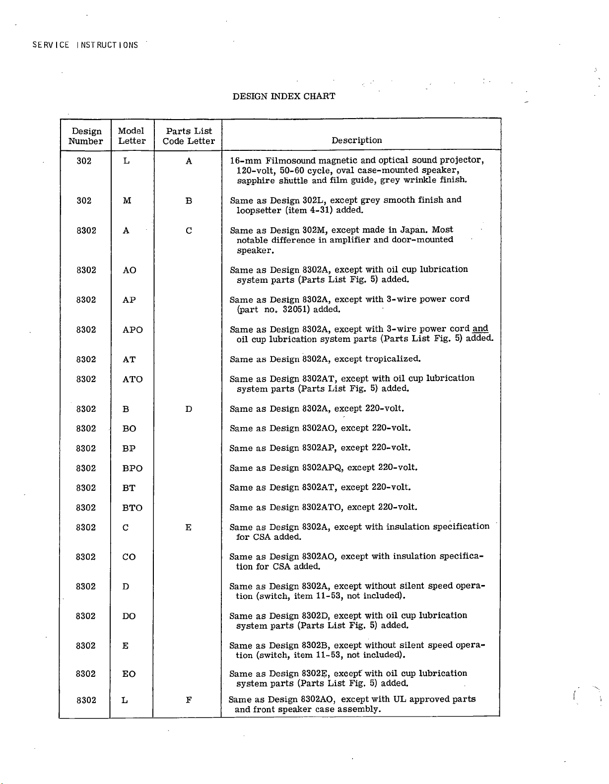
Projector
design
var-
iations
are
listed
in
the
Design
Index
Chart,
preceding
page.
•
SPECIAL
MAINTENANCE
PRECAUTIONS.
For
the
most
part,
disassembly
and
reassembly
of
the
projectors
is
relatively
simple.
Before
attempting
repairs,
however,
it
is
suggested
that
the
serviceman
run
an
operating
test
to
verify
customer
complaint
and
then
check
the
Trouble
Shooting
section
to
determine
the
possible
cause
of
the
trouble.
LUBRICATION.
Proper
lubrication
of
parts
is
of
vital
importance.
When
overhauling
projectors,
always
clean
parts
thoroughly
of
old
lubricant
and
relubricate
during
reassembly
only
with
recommended
Bell
&
Howell
projector
oil
and
grease.
Do
not
over
-lubricate,
and
be
sure
to
wipe
away
any
excess
lubricant
with
a
lint
-free
cloth.
Proper
lubricants
are
indicated
in
paragraph
22.
SPECIAL
SERVICE
TOOLS.
Special
service
tools
available
from
Bell
&
Howell
for
use
in
servicing
Filmosound
Projectors
are
illus-
trated
in
figure
B.
Refer
to
the
accompanying
tool
list
for
tool
numbers
and
applications.
The
tool
number
is
stamped
in
each
Bell
&
Howell
tool.
Figure
A.
16
-MM
Filmosound
Projector
1

SERVICE
INSTRUCTIONS
Fl
2
3
8
9
10
11
G
4
C
5
6
12
13
14
15
16
17
18
19
20
21
22
duN
23
24
25
Figure
B.
Special
Service
Tools
INDEX
NO.
TOOL
NO.
FUNCTION
1
ST-
244-
F1
Fan
housing
bearing
removal
2
S
-10309-F1
Lens
carrier
adjustment
3
S
-4529-N4
Shuttle
tooth
height
gage
4
S
-4007-F14
Quills
(use
with
Index
No.
7)
5
S
-4007-F5
Sleeve
(use
with
Index
No.
7)
6
No.
1459
Clip
(use
with
Index
No.
7)
7
S-4007-
1
Fixture
(for
assembling
shutter
and
counter
shaft
parts)
8
S
-15177-N4
Shim
gage
(for
gear
clearance)
9
S
-4007-F6
Sleeve
(use
with
Index
No.
7)
10
S
-15638-N6
Film
guide
clearance
gage
11
G
-165-F3
Setscrew
wrench
12
G
-167-F3
Setscrew
wrench
(Bristo)
INDEX
NO.
TOOL
NO.
FUNCTION
13
S
-14986-X1
Setscrew
wrench
(Bristo)
14
S
-15177-F3
Cone
(sprocket
installation)
15
S
-15177-N2
Gage
(sprocket
adjusting)
16
S
-15177-N1
Gage
(sprocket
shaft
adj.
)
17
S
-14878-F1
Drift
punch
(bearing
removal)
18
S
-10310-F2
Wrench
(shuttle
shaft
holding)
19
G
-167-X2
Setscrew
wrench
(Bristo)
20
G
-167-F1
Handle
(for
Index
No.
19)
21
G
-165-X2
Setscrew
wrench
(Bristo)
22
G
-165-F1
Handle
(for
Index
No.
21)
23
S
-19028-F4
Wrench
(for
clutch
disassembly)
24
S-19028-
F3
Wrench
(for
clutch
disassembly)
25
S
-12264-F3
Wrench
(for
governor
cap)
2

FILMOSOUND
PROJECTORS
DES.302/8302
AND
NOTE
Disassembly
procedures
are
keyed
and
cross-
referenced
to
the
exploded
views
located
in the
Parts
Catalog
section
of
this
book.
The
ex-
ploded
views
can
be
folded
outward
beyond
the
edge
of
the
book
so
that text
and
illustrations
can
be
referred
to
simultaneously.
Follow
the
procedures
as
outlined,
eliminating
unneces-
sary
steps
where
desired.
1.
AMPLIFIER
PROJECTOR.
(See
figure
1.)
a.
Remove
the
case
feet
(1),
lock
washers
(2)
and
bottom
plate
(3).
Remove
four
screws
(4)
and
carefully
withdraw
the
amplifier
(5)
from
the
projector
case.
Be
sure
to
disconnect
all
connecting
cable
plugs
from
the
amplifier.
NOTE
No
specific
disassembly
instructions
are
given
for
the
amplifier.
Refer
to
the
appropriate
schematic
diagram
at
the
end
of
the
Parts
Catalog
section
for
proper
voltage
and
parts
replacement
information.
Correct
amplifier
troubles
by
normal
circuit
tracing
techniques.
b.
Remove
the
screws
(6),
flat
washers
(7),
cushions
(8)
and
spacers
(9)
and
withdraw
the
projector
(10)
from
the
projector
case
(11).
c.
The
reel
arms
(14)
and
(15)
are
normally
stored
in
the
projector
case.
Remove
the
reel
arm
spring
belts
(12)
and
(13)
by
disconnecting
the
ends
and
carefully
pulling
them
free
of
the
case.
Refer
to
paragraph
15
for
disassembly
instructions
relevant
to
the
rear
reel
arm
and
to
paragraph
16
for
the
front
reel
arm.
2.
PROJECTOR
MAIN
COMPONENTS.
(See
figure
2.)
a.
Remove
the
condenser
assemblies
(1)
and
(2)
and
projection
lens
(3)
from
the
projector.
Refer
to
paragraph
6b
for
disassembly
of
the
relay
condenser
and
to
paragraph
9e
for
disassembly
of
the
45-50mm
condenser.
Do
not
attempt
to
disassemble
the
pro-
jection
lens.
b.
Loosen
the
knurled
screw
(4)
and
remove
the
exciter
lamp
cover
(5).
Press
down
slightly
on
the
exciter
lamp
(6),
twist
the
lamp
and
remove
it
from
its
socket.
c.
The
gear
case
assembly
(14),
blower
housing
(17),
governor
cap
assembly
(19)
and
lamphouse
and
motor
assembly
(20)
can
be
removed
as
a
unit
by
removing
two
screws
(7)
or
(7A)
and
two
Sems
screws
(8);
The
Procedure
screws
(7)
are
used
in
302L
projectors
only;
screws
(7A)
and
support
bracket
(7B)
are
used
in
all
other
models.
d.
Free
the
gear
case
assembly
by
removing
screws
(9)
and
(11),
the
latter
also
serving
to
attach
the
guide
rail
(12)
and
spacer
washers
(13).
Separate
the
gear
case
(14)
from
the
blower
housing,
being
careful
not
to
damage
the
teeth
of
the
counter
gear
(22,
figure
5)
as
it
passes
the
thrust
nut
(1,
figure
8).
When
as-
sembled,
the counter
gear
engages
the
motor
pinion
(3,
figure
8).
e.
Remove
the
screws
(15
and
16)
and
separate
the
blower
housing
(17)
from
the
lamphouse
(20).
Remove
two
screws
(18)
and
separate
the
governor
cap
assem-
bly
(19)
from
the
lamphouse.
3.
GEAR
CASE
-
FRONT
COVER
AND
CLUTCH
MECHANISM.
(See
figure
3.)
a.
Remove
the
pressure
plate
assembly
(1)
from
the
rear
of
the
lens
carrier
and,
if
necessary,
disassemble
as
follows:
Press
in
on
the
spring
cups
(1A)
until
the
cups
and
springs
(1B)
can
be
removed.
Remove
screws
(1C)
and
disassemble
the
remaining
parts.
b.
Remove
the
rubber
knob
(2).
Unscrew
the
hex
nut
(3)
and
partially
unscrew
the
clutch
knob
assembly
(4)
until
the
retaining
ring
(5)
can
be
removed.
Unscrew
the
knob
assembly
completely
and
catch
the
spacer
(6)
as
it
drops
free.
c.
Note
that
a
small
pin
in
the
plate
and
shaft
as-
sembly
(13)
engages
a
hole
in
the
gate
operating
block
(9).
These
two
parts
must
be
disengaged
while
the
front
cover
assembly
(8)
is
being
removed.
Lift
out
the
gate
operating
block
(9).
d.
Unscrew
the
fillister
head
screw
(10)
and
remove
the
gate
operating
lever
(11).
Loosen
the
setscrew
(12)
and
disassemble
the
plate
and
shaft
assembly
(13)
and
eccentric
bushing
(14)
from
the
front
cover.
Unscrew
the
special
screw
(19)
and
carefully
remove
the
idler
gear
shaft
(15),
idler
gear
(16),
eighteen
steel
balls
(17)
and
large
fl
at
washer
(18)
from
the
boss
on
the
rear
of
the
front
cover.
e.
Loosen
the
pilot
screw
(20)
and
disengage
the
tip
of
the
clutch
lever
stud
(21)
from
the
hole
in
the
clutch
lever
(22).
Remove
the
clutch
lever,
torsion
spring
(23)
and
clutch
plunger
(24).
4.
GEAR
CASE
-
SPROCKETS
AND
GEARS.
(See
figure
4.)
a.
Remove
the
two
screws
(1)
and
film
strippers
(2).
3

SERVICE
INSTRUCTIONS
b.
Remove
the
sprocket
guard
screw
(3),
sprocket
guard
assembly
(4),
spring
(5)
and
tension
washer
(6)
from
the
end
of
each
sprocket
shaft.
Use
the
Bristo
wrench
and
handle
(21
and
22,
figure
B)
to
loosen
the
setscrews
(7).
Remove
sprocket
assemblies
(8),
being
careful
not
to
damage
the
felt
washers
located
inside
the
sprockets.
c.
Remove
screws
(9)
and
film
guides
(10).
Remove
screws
(11)
and
lens
carrier
retainers
(12)
and
lift
off
the
lens
carrier
(20).
Remove
the
screw
(13),
ball
retaining
spring
(14)
and
steel
ball
(15)
from
the
lens
carrier.
Unscrew
the
two
screws
(16)
from
the
pressure
plate
adjustment
nuts
(17)
and
disassemble
the
pressure
plate
carrier
(18)
from
the
lens
carrier.
CAUTION
The
inner
tip
of
the
lens
lock
screw
(19)
is
peened
and
this
screw
should
not
be
removed
from
the
lens
carrier.
d.
Note
that
an
ear
on
each
film
tension
clip
(22)
engages
a
slot
in
the
aperture
plate.
Remove
the
screws
(21),
the
film
tension
clips
(22),
the
thrust
spring
(23)
and
the
aperture
plate
(24).
The
302L
projector
is
equipped
with
a
variable
aperture
plate
(see
inset,
figure
4);
all
other
models
are
equipped
with
a
fixed
-aperture
plate.
Remove
the
framer
shaft
assembly
(25).
e.
Loosen
setscrews
(26)
with
the
Bristo
wrench
and
handle
(19
and
20,
figure
B).
Turn
the
setscrews
out
far
enough
to
permit
removal
of
the
sprocket
shafts
(27).
Remove
the
sprocket
shafts,
upper
gear
(28),
and
the
worm
wheel
(29)
with
its
spacer
washer
(30).
Note
that
each
sprocket
shaft
is
drilled
to
re-
ceive
a
felt
oil
wick
(27A).
These
should
be
discarded
and
replaced.
NOTE
All
8302
Models
and
the
302M
are
equipped
with
a
loopsetter
assembly
(31)
which
is
held
in
place
by
the
screw
(21)
which
holds
the
lower
tension
clip
(
22), and
an
adjacent
screw
(9)
which
attaches
the
lower
film
guide
(10).
Do
not
disassemble
unless
the
spring
(31B)
is
in
need
of
replacement.
5.
GEAR
CASE
-
SHUTTER
AND
SHUTTLE.
(See
figure
5.)
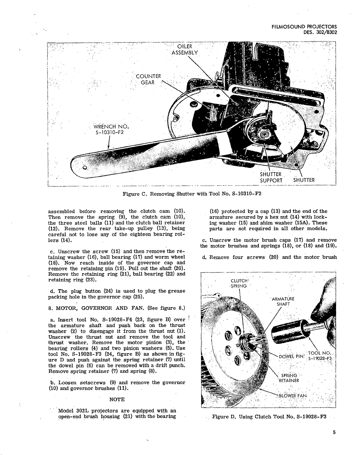
a.
Insert
the
special
wrench
(18,
figure
B)
behind the
shutter
supports
as
shown
in
figure
C.
The
wrench
must
engage
the
flats
on
the
shuttle
shaft
(13).
Re-
move
shutter
retaining
nut
(1)
with
an
open-end
wrench
and
lift
out
the
shutter
supports
(2)
and
the
shutter
(3).
The
oil
baffle
(4)
and
lubricator
assem-
bly
(5)
should
be
removed
together,
as
a
unit.
Re-
moval
of
the
special
screws
(7)
will
free
the
lubricator
assembly
(5),
shuttle
(8)
and
shuttle
pins
(9).
A
"class
-
fit"
number
is
etched
into
each
shuttle
in
the
location
indicated
by
the
letter
A
in
figure
5.
If
the
shuttle
requires
replacement,
be
sure
that
the
new
shuttle
has
the
same
class
fit
number
as
the
old
one.
b.
Before
removing
the
parts
indexed
10
through
24,
note
the
location
of
the
steel
balls
(12,
14,
21
and
23).
When
repairs
necessitate
the
complete
disassembly
of
the
gear
case,
these
steel
balls
must
be
discarded
and
replaced
with
new
ones.
NOTE
Steel
balls
used
by
Bell
&
Howell
are
carefully
graded
and
balls
of
different
grades
must
not
be
intermixed.
When
ordered
in
quantities
of
1000
or
more,
the
grade
is
indicated
on
the
bottle.
When
ordered
in
quantities
of
less
than
1000,
the
balls
are
all
of
one
grade
and
must
not
be
intermixed
with
any
steel
balls
you
already
may
have
on
hand.
c.
Remove
the
shoulder
'screw
(10A),
spring
(10B)
and
collar
(11)
and
remove
and
discard
the
steel
balls
(12).
Withdraw
the
shuttle
shaft
(13)
from
the
rear
of
the
gear
case
and
remove
and
discard
the
steel
balls
(14).
All
steel
balls
(12)
and
(14)
must
be
replaced
with new
ones
when
the
gear
case
parts
are
reassem-
bled.
Remove
the
oil
felt
(15)
which
wraps
around
the
shuttle
shaft.
If
excessively
dirty,
replace
this
felt.
d.
Loosen
two
setscrews
(16)
and
remove
the
worm
drive
extension
(17).
Loosen
the
setscrews
(18
and
19)
and
withdraw
the
worm
gear
(20).
Discard
the
steel
balls
(21).
From
the
rear
of
the
gear
case,
re-
move
the
counter
gear
(22),
steel
balls
(23),
and
the
oil
felt
(24).
Discard
the
steel
balls.
e.
Remove
the
flat
head
screw
(25)
and
the
spring
clamp
(26).
Remove
the
oiler
felt
(27)
from
the
hole
between
the
two
bearings
(28)
with
a
tweezers.
If
either
or
both
of
the
bearings
(28)
are
in
need
of
replacement,
they
can
be
removed
by
driving
them
out
with
the
special
drift
punch
(17,
figure
B).
Be
sure
to
save
the
shims
(29)
located
behind
the
shoulder
of
the
bearings.
6.
BLOWER
HOUSING.
(See
figure
6.)
a.
Note
that
Design
302L
projectors
are
equipped
with
the
adjustable
fire
shutter
(items
1
through
5);
all
other
models
are
equipped
with
the
manually
controlled
heat
filter
(items
15
through
20).
Disas-
semble
parts
as
necessary
for
replacement.
b.
When
disassembling
the
condenser
assembly
(9),
note
that
the
condenser
for
Design
302L
projector
has
a
one-piece
condenser
holder
and
handle;
in
all
other
models,
the
condenser
handle
is
removable.
7.
GOVERNOR
CAP
ASSEMBLY.
(See
figure
7.)
a.
Unscrew
the
special
nut
(1)
with
a
spanner.
wrench.
Then
unscrew
the
fillister
head
screw
(2)
and
remove
the
radial
bearing
(3).
Remove
the
worm
shaft
and
drive
blade
(4)
and
felt
washer
(5).
Use
the
special
tool
(25,
figure
B)
to
remove
screw
(6).
Remove
clutch
cover
(7)
and
bronze
washer
(8),
taking
care
not
to
dislodge
the
spring
(9)
or
steel
balls
(11).
b.
Note
how
the
parts
indexed
9
through
12
are
4
FILMOSOUND
PROJECTORS
DES.
302/8302
OILER
ASSEMBLY
COUNTER
GEAR
WRENCH
NO.
S
-10310-F2
V
SHUTTER
SUPPORT
SHUTTER
Figure
C.
Removing
Shutter
with
Tool
No.
S
-10310-F2
assembled
before
removing
the
clutch
cam
(10).
Then
remove
the
spring
(9),
the
clutch
cam
(10),
the
three
steel
balls
(11)
and
the
clutch
ball
retainer
(12).
Remove
the
rear
take-up
pulley
(13),
being
careful
not
to
lose
any
of
the
eighteen
bearing
rol-
lers
(14).
c.
Unscrew
the
screw
(15)
and
then
remove
the
re-
taining
washer
(16),
ball
bearing
(17)
and
worm
wheel
(18).
Now
reach
inside
of
the
governor
cap
and
remove
the
retaining
pin
(19).
Pull
out
the
shaft
(20).
Remove
the
retaining
ring
(21),
ball
bearing
(22)
and
retaining
ring
(23).
d.
The
plug
button
(24)
is
used
to
plug
the
grease
packing
hole
in
the
governor
cap
(25).
8.
MOTOR,
GOVERNOR
AND
FAN.
(See
figure
8.)
a.
Insert
tool
No.
S
-19028-F4
(23,
figure
B)
over
the
armature
shaft
and
push
back
on
the
thrust
washer
(2)
to
disengage
it
from
the
thrust
nut
(1).
Unscrew
the
thrust
nut
and
remove
the
tool
and
thrust
washer.
Remove
the
motor
pinion
(3),
the
bearing
rollers
(4)
and
two
pinion
washers
(5).
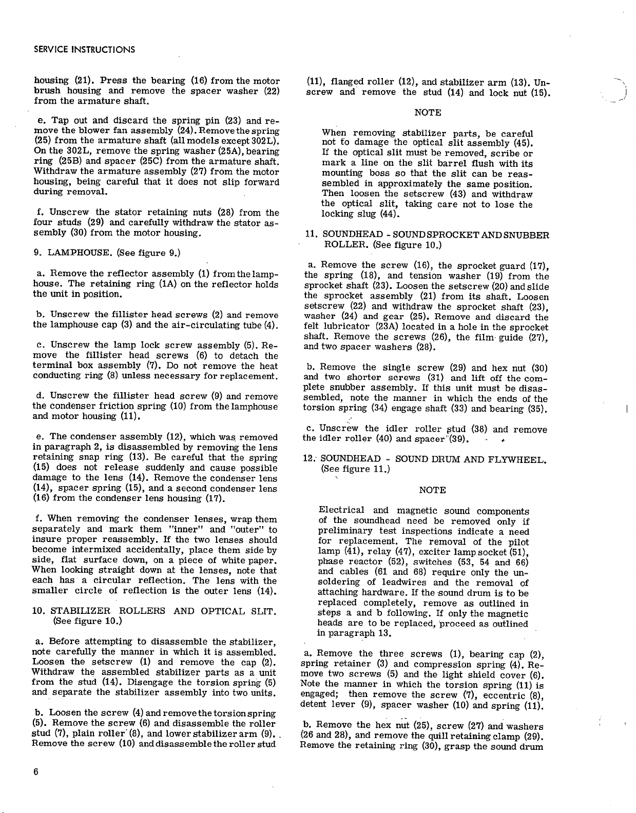
Use
tool
No.
S
-19028-F3
(24,
figure
B)
as
shown
in
fig-
ure
D
and
push
against
the
spring
retainer
(7)
until
the
dowel
pin
(6)
can
be
removed
with
a
drift
punch.
Remove
spring
retainer
(7)
and
spring
(8).
b.
Loosen
setscrews
(9)
and
remove
the
governor
(10)
and
governor
brushes
(11).
NOTE
Model
302L
projectors
are
equipped
with
an
open-end
brush
housing
(21)
with
the
bearing
(16)
protected
by
a
cap
(13)
and
the
end
of
the
armature
secured
by
a
hex
nut
(14)
with
lock-
ing
washer
(15)
and
shim
washer
(15A).
These
parts
are
not
required
in
all
other
models.
c.
Unscrew
the
motor
brush
caps
(17)
and
remove
the
motor
brushes
and
springs
(18),
or
(18)
and
(19).
d.
Remove
four
screws
(20)
and
the
motor
brush
CLUTCH
SPRING
'ARMATURE
SHAFT
TOOL
NO,
DOWEL
PIN
S
-19028-F3
SPRING
'RETAINER
"BLOWER
FAN
Figure
D.
Using
Clutch
Tool
No.
S
-19028-F3
5
SERVICE
INSTRUCTIONS
housing
(21).
Press
the
bearing
(16)
from
the
motor
brush
housing
and
remove
the
spacer
washer
(22)
from
the
armature
shaft.
e.
Tap
out
and
discard
the
spring
pin
(23)
and
re-
move
the
blower
fan
assembly
(24).
Remove
the
spring
(25)
from
the
armature
shaft
(all
models
except
302L).
On
the
302L,
remove
the
spring
washer
(25A),
bearing
ring
(25B)
and
spacer
(25C)
from
the
armature
shaft.
Withdraw
the
armature
assembly
(27)
from
the
motor
housing,
being
careful
that
it
does
not
slip
forward
during
removal.
f.
Unscrew
the
stator
retaining
nuts
(28)
from
the
four
studs
(29)
and
carefully
withdraw
the
stator
as-
sembly
(30)
from
the
motor
housing.
9.
LAMPHOUSE.
(See
figure
9.)
a.
Remove
the
reflector
assembly
(1)
from
the
lamp
-
house.
The
retaining
ring
(1A)
on
the
reflector
holds
the
unit
in
position.
b.
Unscrew
the
fillister
head
screws
(2)
and
remove
the
lamphouse
cap
(3)
and
the
air
-circulating
tube
(4).
c.
Unscrew
the
lamp
lock
screw
assembly
(5).
Re-
move
the
fillister
head
screws
(6)
to
detach
the
terminal
box
assembly
(7).
Do
not
remove
the
heat
conducting
ring
(8)
unless
necessary
for
replacement.
d.
Unscrew
the
fillister
head
screw
(9)
and
remove
the
condenser
friction
spring
(10)
from
the
lamphouse
and
motor
housing
(11).
e.
The
condenser
assembly
(12),
which
was
removed
in
paragraph
2,
is
disassembled
by
removing
the
lens
retaining
snap
ring
(13).
Be
careful
that
the
spring
(15)
does
not
release
suddenly
and
cause
possible
damage
to
the
lens
(14).
Remove
the
condenser
lens
(14),
spacer
spring
(15),
and
a
second
condenser
lens
(16)
from
the
condenser
lens
housing
(17).
f.
When
removing
the
condenser
lenses,
wrap
them
separately
and
mark
them
"inner"
and
"outer"
to
insure
proper
reassembly.
If
the
two
lenses
should
become
intermixed
accidentally,
place
them
side
by
side,
fl
at
surface
down,
on
a
piece
of
white
paper.
When
looking
straight
down
at
the
lenses,
note
that
each
has
a
circular
reflection.
The
lens
with
the
smaller
circle
of
reflection
is
the
outer
lens
(14).
10.
STABILIZER
ROLLERS
AND
OPTICAL
SLIT.
(See
figure
10.)
a.
Before
attempting
to
disassemble
the
stabilizer,
note
carefully
the
manner
in
which
it
is
assembled.
Loosen
the
setscrew
(1)
and
remove
the
cap
(2).
Withdraw
the
assembled
stabilizer
parts
as
a
unit
from
the
stud
(14).
Disengage
the
torsion
spring
(5)
and
separate
the
stabilizer
assembly
into
two
units.
b.
Loosen
the
screw
(4)
and
remove
the
torsion
spring
(5).
Remove
the
screw
(6)
and
disassemble
the
roller
stud
(7),
plain
roller
(8),
and
lower
stabilizer
arm
(9).
Remove
the
screw
(10)
and
disassemble
the
roller
stud
(11),
fl
anged
roller
(12),
and
stabilizer
arm
(13).
Un-
screw
and
remove
the
stud
(14)
and
lock
nut
(15).
NOTE
When
removing
stabilizer
parts,
be
careful
not
to
damage
the
optical
slit
assembly
(45).
If
the
optical
slit
must
be
removed,
scribe
or
mark
a
line
on
the
slit
barrel
fl
ush
with
its
mounting
boss
so
that
the
slit
can
be
reas-
sembled
in
approximately
the
same
position.
Then
loosen
the
setscrew
(43)
and
withdraw
the
optical
slit,
taking
care
not
to
lose
the
locking
slug
(44).
11.
SOUNDHEAD
-
SOUND
SPROCKET
AND
SNUBBER
ROLLER.
(See
figure
10.)
a.
Remove
the
screw
(16),
the
sprocket
guard
(17),
the
spring
(18),
and
tension
washer
(19)
from
the
sprocket
shaft
(23).
Loosen
the
setscrew
(20)
and
slide
the
sprocket
assembly
(21)
from
its
shaft.
Loosen
setscrew
(22)
and
withdraw
the
sprocket
shaft
(23),
washer
(24)
and
gear
(25).
Remove
and
discard
the
felt
lubricator
(23A)
located
in
a
hole
in
the
sprocket
shaft.
Remove
the
screws
(26),
the
film
guide
(27),
and
two
spacer
washers
(28).
b.
Remove
the
single
screw
(29)
and
hex
nut
(30)
and
two
shorter
screws
(31)
and
lift
off
the
com-
plete
snubber
assembly.
If
this
unit
must
be
disas-
sembled,
note
the
manner
in
which
the
ends
of
the
torsion
spring
(34)
engage
shaft
(33)
and
bearing
(35).
c.
Unscrew
the
idler
roller
stud
(38)
and
remove
the
idler
roller
(40)
and
spacer'
(39).
12.
-
SOUNDHEAD
-
SOUND
DRUM
AND
FLYWHEEL.
(See
figure
11.)
NOTE
Electrical
and
magnetic
sound
components
of
the
soundhead
need
be
removed
only
if
preliminary
test
inspections
indicate
a
need
for
replacement.
The
removal
of
the
pilot
lamp
(41),
relay
(47),
exciter
lamp
socket
(51),
phase
reactor
(52),
switches
(53,
54
and
66)
and
cables
(61
and
68)
require
only
the
un-
soldering
of
leadwires
and
the
removal
of
attaching
hardware.
If
the
sound
drum
is
to
be
replaced
completely,
remove
as
outlined
in
steps
a
and
b
following.
If
only
the
magnetic
heads
are
to
be
replaced,
proceed
as
outlined
in
paragraph
13.
a.
Remove
the
three
screws
(1),
bearing
cap
(2),
spring
retainer
(3)
and
compression
spring
(4).
Re-
move
two
screws
(5)
and
the
light
shield
cover
(6).
Note
the
manner
in
which
the
torsion
spring
(11)
is
engaged;
then
remove
the
screw
(7),
eccentric
(8),
detent
lever
(9),
spacer
washer
(10)
and
spring
(11).
b.
Remove
the
hex
nut
(25),
screw
(27)
and
washers
(26
and
28),
and
remove
the
quill
retaining
clamp
(29).
Remove
the
retaining
ring
(30),
grasp
the
sound
drum
6

FILMOSOUND
PROJECTORS
DES.
302/8302
and,
while
supporting
the
weight
of
the
flywheel,
with-
draw
the
sound
drum
from
the
soundhead
until
the
rear
end
of
the
shaft
is
free
of
the
bearing
(36).
Re-
move
the
fl
ywheel
retaining
spring
(32)
and
withdraw
the
sound
drum
assembly
completely
from
the
sound
-
head
casting,
meanwhile
lifting
out
the
fl
ywheel
(33).
Do
not
remove
the
lever
(35)
unless
in
need
of
re-
placement.
13.
MAGNETIC
HEADS
AND
COILS.
(See
figure
11A.)
NOTE
The
magnetic
heads
and
coils
of
the
sound
drum
assembly
can
be
replaced
by
following
the
pro-
cedure
outlined
below.
The
sound
drum
need
not
be
removed
from
the
sound
head
casting
to
make
these
replacements.
Unless
damaged
by
rough
handling
or
improper
adjustment,
the
heads
have
a
relatively
long
life.
Be
sure
to
check
out
other
possible
causes
of
improper
magnetic
sound
reproduction
(dirt
on
heads
or
film,
old
or
damaged
film,
improper
magnetic
striping)
before
replacing
heads.
a.
Inspect
the
faces
of
the
heads
(figure
E)
with
a
mag-
nifying
glass.
Fine
scratches
in
the
direction
of
film
travel
will
seldom
affect
sound
quality.
Deep
grooves
or
steps,
usually
caused
by
extensive
operation
with
quarter
or
half-track
film,
will
prevent
proper
track
contact
area
and
are
cause
for
head
replacement.
•-
rf
STABILIZER
ASSEMBLY.
•
ERASE
HEAD
•
RECORD
-PLAYBACK
HEAD
•
Figure
E.
Magnetic
Heads
and
Sound
Drum
b.
Use
a
low
-voltage
AC
supply
and
an
AC
voltmeter
to
check
the
continuity
of
the
head
coils.
A
DC
powered
ohmmeter
will
magnetize
the
heads.
(See
figure
F
for
terminal
configuration.)
Open
head
circuits,
unless
traceable
to
broken
leads
at
the
terminal
ring,
will
require
replacement
of
the
damaged
coil,
as
outlined
in
the
following
steps.
FINISH
START
ERASE
HEAD
COMMON
LOAD
ON
LATE
CODE'
Z
HEADS
START
FINISH
START
BIAS
8 Ohm
3
FOR
CODE
W
AND
X
UNITS
FINISH
2
S
F
•
3
4
RECORD
4.5
2
5
ERASE
1 Ohm
RECORD
HEAD
I
ERASE
2
CODE
S
-START
OF
WINDING
F
-FINISH
OF
WINDING
•
5
4
S S
FOR
CODE
Y
AND
Z
UNITS
4.5 Ohm
RECORD
Figure
F.
Magnetic
Head
Coil
Identification
and
Connections
7

SERVICE
INSTRUCTIONS
c.
Shift
the
function
lever
to
the
OPT
(optical)
posi-
tion
and
remove
the
screw
(12,
figure
11),
washer
(13),
and
roller
(14).
Remove
two
screws
(5)
and
the,
light
shield
cover
(6).
d.
Refer
to
figure
11A
and
remove
the
screw
(6)
and
washer
(7).
Shift
the
function
lever
to
the
MAG
(mag-
netic)
position
and
remove
the
screw
and
washer
at
the
opposite
end
of
the
hum
shield.
Place
the
function
lever
at
a
point
mid
-way
between
the
optical
and
magnetic
positions,
and
carefully
lift
off
the
shield
cover
(5).
Remove
the
remaining
screw
(6)
and
washer
(7)
and
lift
off
the
hum
shield
(4).
e.
Loosen
the
screw
(10,
figure
11A),
and
carefully
lift
the
record
-playback
arm
(16)
as
far
as
possible
but
without
placing
a
strain
on
the
coil
leads.
While
holding
the
arm
in
this
position,
tighten
the
screw
(10).
f.
Shift
the
function
lever
to
a
position
such
that
the
record
-playback
head
(figure
E)
is
facing
directly
up.
Carefully
apply
a
drop
or
two
of
acetone
at
the
points
where
the
head
pole
pieces
enter
the
coil
forms.
CAUTION
Do
not
apply
acetone
to
the
coils.
If
acetone
runs
onto
the
coil
windings,
remove
at
once
with
a
clean,
lint
-free
cloth.
g.
Allow
approximately
30
seconds
for
the
acetone
to
soften
the
cement.
Then,
while
holding
the
arm
(16,
figure
11A)
firmly
in
place,
insert
a
jeweler's
screwdriver
between
the
pole
piece
(11)
and
the
coil
form
and
carefully
pry
the
coils
(12)
from
the
arm.
As
soon
as
one
coil
begins
to
loosen,
shift
the
screw-
driver
to
the
other
coil
and
begin
to
loosen
this
one.
.
When
both
coils
are
loose,
slip
them
away
from
the
pole
piece.
h.
With
the
function
lever
in
mid
-position,
loosen the
center
screw
in
the
arm
(16)
and
remove
the
record
-
playback
head.
i.
The
erase
head
is
removed
in
the
same
manner
as
the
record
-playback
head
(steps
e
through
h,
preceding).
j.
With
the
heads
(pole
pieces)
removed,
the
resist-
ance
of
the
coils
can
be
checked
without
danger
of
magnetization.
Remove
twine
and
tape
(2)
from
the
terminal
ring
(3)
carefully
unsolder
the
coil
leads
from
their
terminals.
The
resistance
of
the
coils
should
be
approximately
as
indicated
in
figure
F.
Shorted
coils
must
be
replaced.
k.
Should
it
be
necessary
to
replace
a
coil,
care-
fully
disconnect
the
coil
leads
from the
terminal
ring.
Coil
leads
must
be
connected
as
shown
in
figure
F.
Coils
and
their
leads
can
be
identified
as
follows:
Erase
coil
-
wound
with
heavier
gage
wire
than
the
record
-playback
coil.
The
longest
of
its
two
tinned
leads
is
the
start
of
the
winding.
Bias
coil
(not
in
8302L
Projectors)
7
part
of
re-
cord
-playback
coil
assembly.
Wound
with
heavier
gage
wire
than
record
coil
and
the
longest
of
its
two
leads
is
the
start
of
the
winding.
Record
coil
-
part
of
record
-playback
coil
as-
sembly.
Wound
with
lighter
gage
wire
than
the
erase
coil.
NOTE
Refer
to
paragraph
42
for
head
and
coil
reas-
sembly
instructions.
14.
PROJECTOR
CASE.
(See
figure
12).
Except
for
the
carrying
handle,
tilt
mechanism
and
speaker,
it
is
doubtful
that
projector
case
parts
will
require
replacement.
Merely
refer
to
the
ex-
ploded
view
illustrations
and
remove
damaged
parts
in
indexed
order.
Inspect
speaker
cone
for
damage.
In
Design
8302L
Projector,
the
speaker
is
mounted
in
the
front
of
the
projector
case.
15.
REAR
REEL
ARM.
(See
figure
13.)
a.
Remove
the
fabric
take-up
belt
(1).
Press
out
the
shaft
(2)
and
remove
the
take-up
arm
assembly
(3
through
14).
b.
Remove
the
screw
(3)
and
twist
the
cover
(4)
slightly
to
disengage
the
return
spring
(6)
from
the
lock
pin
(14A).
Lift
off
the
cover
and
return
spring.
c.
Remove
the
screw
(7),
plunger
(8),
and
rewind
gear
(9).
Unscrew
the
hex
nut
(10)
and
the
bearing
retaining
ring
(11).
Remove
the
nineteen
steel
balls
(13),
take-up
pulley
(12)
and
nineteen
more
steel
balls
(13)
from
the
take-up
arm
assembly
(14).
Be
careful
not
to
lose
any
of
the
steel
balls.
d.
Unscrew
the
rewind
drive
gear
(15)
from
the
shaft
of
the
take-up
drive
pulley
assembly
(16)
by
turning
clockwise
to
loosen
the
left-hand
thread.
If
necessary,
wrap
tape
around
the
rewind
drive
gear
(15)
and
drive
pulley
(16)
so
that
they
may
be
firmly
grasped
to
unscrew
one
from
the
other.
Remove
take-
up
drive
pulley
slowly,
cupping
hand
around
it
to
catch
the
plunger
(17)
and
compression
spring
(18)
which
will
pop
out
as
the
pulley
is
removed.
e.
Carefully
remote
the
spring
(22).
Unscrew
the
shoulder
screw
(20)
to
remove
the
rewind
lock
lever
(21).
The
headless
setscrew
(19)
acts
as
a
plug
for
the
grease
packing
hole
and
is
easily
removed.
f.
The
bearing
retainer
ring
(23)
is
press
fitted
in
place
and
will
have
to
be
pried
out
if
it
ever
be-
comes
necessary
to
remove
the
sixteen
roller
bear-
ings
(24)
from
the
rear
reel
arm
(25).
g.
To
disassemble
the
take-up
spindle
pulley
assem-
bly
(12),
support
the
reel
end
of
the
spindle
in
a
"Vee"
block
and
use
a
straight
punch
to
drive
out
the
roll
pin
(12A).
Separate
the
reel
clip
(12B)
from
the
spindle.
8

FILMOSOUND
PROJECTORS
DES.
302/8302
16.
FRONT
REEL
ARM.
(See
figure
14.)
a.
Unscrew
the
clutch
cover
screw
(1)
and
remove
the
cover
(2)
and
bronze
washer
(3).
Carefully
remove
the
three
steel
balls
(4),
clutch
cam
(5)
and
clutch
ball
retainer
(6).
b.
Lift
the
pulley
(7),
with
bearing
rollers
(8),
the
shim
or
shims
(9)
and
the
spindle
washer
(10)
from
the
reel
spindle
(13).
The
same
number
of
shims
(9)
must
be
installed
during
reassembly
of
the
reel
arm.
c.
Remove
split
retaining
washer
(11)
and
disas-
semble
the
reel
spindle
(13)
and
washers
(12
and
14)
from
the
front
reel
arm.
d.
Unscrew
the
bearing
retainer
(15)
and
press
the
bearing
(16)
from
the
front
reel
arm.
e.
Support
the
reel
end
of
the
spindle
in
a
"V"
block
and
drive
out
roll
pin
(13A)
with
a
straight
punch
to
free
the
reel
clip
(13B),
plunger
(13C)
and
spring
(13D).
18.
CLEANING
OPTICAL
PARTS.
Clean
the
projection
lens,
both
condenser
as-
semblies
and
the
reflector
with
Bell
&
Howell
lens
cleaning
tissue
and
Optikleen
lens
cleaning
fluid.
First
remove
accumulated
dust
with
a
camel's
hair
brush;
then
wipe
on
lens
cleaning
fluid
with
a
clean,
soft
cloth
and
polish
with
lens
tissue.
Be
careful
not
to
leave
fingerprints
on
lens
surfaces,
and
do
not
at-
tempt
to
disassemble
the
projection
lens.
Clean
only
the
exposed
lens
elements.
19.
CLEANING
OPTICAL
SLIT
AND
MAGNETIC
HEADS.
a.
Clean
the
exposed
elements
of
the
optical
slit
as-
sembly
(45,
figure
10)
with
lens
tissue
wrapped
about
a
toothpick.
If
lens
cleaning
fluid
is
necessary,
dampen
the
lens
tissue
sparingly.
Do
not
disassemble
the
optical
slit
assembly.
b.
Clean
the
mirror
on
the
sound
drum
assembly
(31,
figure
11)
in
the
same
manner
as
the
optical
slit
assembly,
being
careful
not
to
disturb
the
mir-
ror
mounting
in
the
process.
c.
Clean
the
magnetic
heads
with
a
piece
of
linen
wrapped
about
a
toothpick
and
dipped
in
denatured
alcohol.
Do
not
flood
the
heads
with
alcohol;
moisten
only
enough
to
remove
foreign
materials.
CAUTION
Only
alcohol
should
be
used
as
a
cleaning
agent
for
the
magnetic
heads.
17.
AMPLIFIER.
(See
figure
15.)
a.
Normally,
the
replacement
of
tubes
and
the
fuse
is
the
only
disassembly
necessary.
b.
To
remove
tubes,
simply
pull
them
straight
up
from
the
sockets,
taking
care
not
to
damage
tube
pins,
particularly
on
miniature
tubes.
c.
The
knobs
on
the
front
panel
are
secured
with
set-
screws.
The
microphone
jack
is
secured
with
a
nut.
d.
To
gain
access
to
internal
parts
of
the
amplifier,
unscrew
four
sheet
metal
screws,
from
the
bottom
and
remove
the
base
plate
assembly.
Take
care
not
to
pull
the
leads
which
are
solder
grounded
to
a
terminal
on
the
inside
of
the
base
assembly.
Refer
to
the
schematic
diagrams,
figures
17
and
18
for
complete
amplifier
service
and
parts
replacement
information.
20.
CLEANING
FILM
PATH
PARTS.
Film
path
parts
are
those
components
(aperture
plate,
pressure
plate,
sprockets,
film
rollers)
which
are
contacted
by
the
film
during
operation.
In
addi-
tion
to
the
normal
accumulation
of
dirt,
such
parts
may
also
acquire
a
build-up
of
film
emulsion.
Clean
with
a
soft
cloth
dampened
with
carbon
-tetrachloride.
If
deposits
of
hardened
emulsion
remain,
scrape
a-
way
such
deposits
with
a
toothpick
or
sharpened
orange
stick.
An
aperture
brush
or
toothpick
can
be
used
to
remove
foreign
matter
from
between
sprocket
teeth.
21.
CLEANING
MECHANICAL
PARTS.
Blow
dust
and
dirt
from
chassis
and
housings
with
compressed
air,
and
wipe
electrical
compo-
nents
(tubes,
transformers,
motors)
with
a
clean,
soft
cloth.
All
other
mechanical
parts
should
be
cleaned
with
carbon
tetrachloride
to
remove
old
grease
and
lubricating
oil.
Dry
parts
thoroughly
with
compressed
air
or
with
soft,
lint
-free
cloths.
During
reassembly,
be
sure
to
lubricate
parts
as
necessary.
22.
LUBRICATION
INSTRUCTIONS.
a.
Whenever
it
is
necessary
to
disassemble
the
intermittent
mechanism
or
to
perform
extensive
major
repairs
to
the
gear
housing,
all
oil
storage
pads
should
be
removed
and
discarded.
Cover
the
bottom
of
a
small
pan
with
about
1/4
-inch
of
oil
(Bell
&
Howell
Spec.
No.
1543)
and
insert
one
end
of
the
new
wick
or
pad
in
this
oil.
Do
not
immerse
9

SERVICE
INSTRUCTIONS
pads
in
oil.
Allow
wicks
to
stand
until
they
are
completely
saturated
with
oil;
then
remove
them
from
the
pan
and
allow
the
excess
to
drain
away.
NOTE
When
installing
the
lubricator
assembly
(5,
figure
5),
make
certain
that
the
tongue
of
the
pad
is
firmly
in
contact
with
the
shuttle
cam
before
tightening
shuttle
pin
retaining
screws.
b.
Place
a
light
film
of
oil
(Spec.
No.
1543)
on
all
rotating
shafts
during
reassembly
and
speck
all
gear
teeth
with
grease
(Spec.
No.
1544).
c.
After
reel
arms
are
reassembled,
remove
the
grease
plug
and
pack
the
cavity
around
the
spindle
parts
with
grease
(Spec.
No.
345).
d.
When
governor
cap
is
reassembled,
remove
the
grease
cup
and
pack
the
housing
with
grease
(Spec.
No.
345).
23.
GENERAL
REPAIR
INSTRUCTIONS.
Except
as
noted
below,
reconditioning
of
projec-
tor
parts
for
possible
re
-use
is
impractical.
When
a
part
is
obviously
damaged,
or
its
condition
is
doubtful,
replace
with
a
new
part.
Specific
repair
instructions
for
the
amplifier
and
sound
system
will
be
found
in
paragraphs
24
through
37,
follow-
ing.
Refer
to
the
wiring
diagrams
at
the
end
of
the
parts
list
for
electrical
circuitry
and
proper
re-
placement
parts.
a.
Film
path
components
should
be
inspected
for
signs
of
scratches
or
rough
burrs
that
might
dam-
age
the
film.
Minor
defects
can
sometimes
be
re-
moved
by
polishing
with
fine
emery
cloth.
b.
Binding
in
the
heat
filter
or
fire
shutter
com-
ponents
(figure
6)
can
sometimes
be
attributed
to
bent
parts.
Straighten
parts
as
necessary
and
check
operation.
c.
Be
sure
to
inspect
all
wiring
for
frayed
insula-
tion
or
bare
spots.
Such
wiring
should
be
replaced.
Make
certain
that
all
solder
connections
are
secure.
24.
ERASE
FAILURE.
a.
With
projector
and
amplifier
set
for
magnetic
recording,
measure
the
RF
voltage
across
pins
1
and
3
on
rear
amplifier
receptacle
connector
J6.
All
RF
measurements
should
be
made
with
a
suit-
able
vacuum
tube
voltmeter.
With
the
record
inter-
lock
in,
reading
should
be
6
volts
across
the
erase
winding
and
0.3
volts
across
the
bias
winding
(5.5
and
1.5
volts
respectively
for
8302L
Projectors).
b.
If
no
voltage
is
present,
or
if
voltage
is
incor-
rect,
check
for
continuous
ground
or
open
up
to
the
interlock
relay.
Make
certain
that
relay
con-
tact
is
functioning
properly.
Check
to
see
that
neon
indicator
lights
and
stays
lit
with
the
projector
running
forward
and
the
V1.
record
button
pressed
in.
c.
Check.
RF
voltages
at
terminal
strip
mounted
inside
the
soundhead
casting.
Check
continuity
with
an
ohmmeter.
NOTE
Any
tools
used
in
the
vicinity
of
the
mag-
netic
head
should
be
demagnetized
immedi-
ately
before
use.
If
a
DC
ohmmeter
is
used,
the
input
transformer
and
head
must
be
de-
magnetized;
therefore,
use
only
a
low
-volt-
age
AC
supply
and
AC
voltmeter
for
con-
tinuity
checks.
25.
NOISE
CAUSED
BY
TUBES
OR
TRANSISTOR.
S
a.
Mica
leakage
generates
a
frying
or
has
noise.
If
this
noise
occurs
when
the
amplifier
r
is
in
the
op-
tical
position,
replace
tube
Ho
ever,
first
make
certain
no
stray
lite
is
striking
the
photocell.
b.
If
the
noise
occurs
only
when
in
the
magnetic
playback
position,
replace
the
transistor
(Q1
for
8302L
Projectors;
TR1
for
all
other
projectors).
26.
FLOATING
MOUNT
FOR
12AY7
TUBE.
When
installing
the
12AY7
tube,
apply
no
more
pressure
than
is
absolutely
necessary
to
reset
the
tube
firmly
in
its
socket.
Excessive
pressure
may
cause
the
socket
to
slip
out
of
the
bottom
of
the
shield,
thereby
interfering
with
the
function
of
the
floating
mount.
Also,
make
certain
that
the
tube
shield
is
vertical
and
not
cocked
at
an
angle,
or
it
may
interfere
with
flywheel
rotation.
NOTE
Be
sure
to
check
all
tube
pins
and
straighten,
if
necessary,
before
installing
tubes.
Use
a
commercial
tube
pin
straightener
or
long
-
nose
pliers.
27.
MICROPHONICS.
a.
Microphonics
which
occur
when
the
amplifier
is
in
the
optical
playback
position
is
caused
either
by
a
microphonic
photocell
or
microphonic
tubes.
Cor-
rect
trouble
by
trial
replacement.
b.
Microphonics
which
occur
when
the
amplifier
is
in
the
magnetic
playback
position
only
is
caused
either
by
a
microphonic
12AY7
tube
or
microphonic
playback
head.
28.
TEST
PROBE.
Amplifier
output
voltage
can
best
be
checked
with
a
test
probe
which
can
be
fabricated
from
standard
radio
components
as
shown
in
figure
G.
29.
CHECKING
THE
AMPLIFIER.
a.
Check
the
quality
of
all
tubes
on
a
standard
tube
10
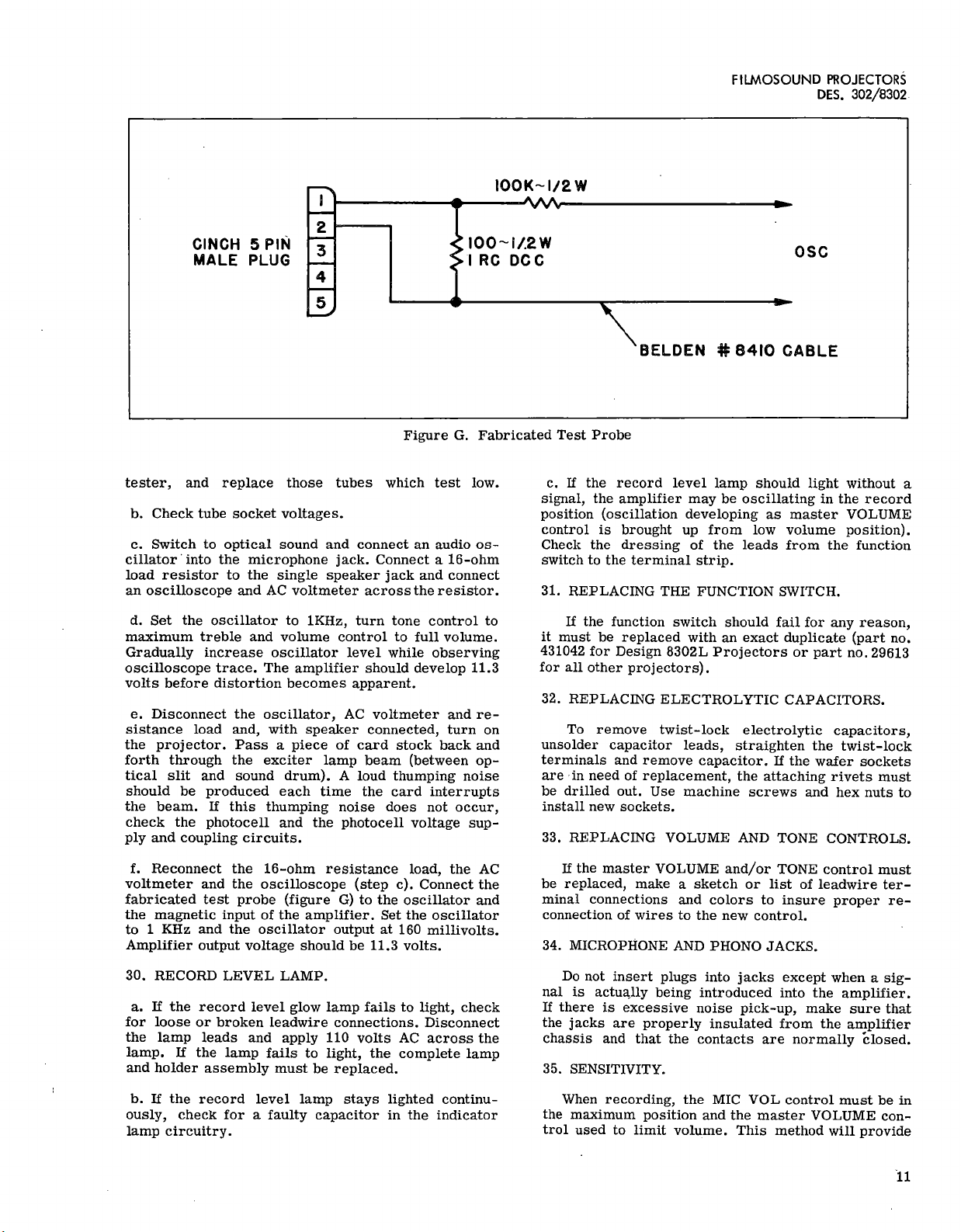
FILMOSOUND
PROJECTORS
DES.
302/8302
100K-1/2W
CINCH
5
PIN
MALE
PLUG
2
3
4
I00
1/2W
I
RC
DC
C
OSC
BELDEN
#
8410
CABLE
Figure
G.
Fabricated
Test
Probe
tester,
and
replace
those
tubes
which
test
low.
b.
Check
tube
socket
voltages.
c.
Switch
to
optical
sound
and
connect
an
audio
os-
cillator
into
the
microphone
jack.
Connect
a
16
-ohm
load
resistor
to
the
single
speaker
jack
and
connect
an
oscilloscope
and
AC
voltmeter
across
the
resistor.
d.
Set
the
oscillator
to
1KHz,
turn
tone
control
to
maximum
treble
and
volume
control
to
full
volume.
Gradually
increase
oscillator
level
while
observing
oscilloscope
trace.
The
amplifier
should
develop
11.3
volts
before
distortion
becomes
apparent.
e.
Disconnect
the
oscillator,
AC
voltmeter
and
re-
sistance
load
and,
with
speaker
connected,
turn
on
the
projector.
Pass
a
piece
of
card
stock
back
and
forth
through
the
exciter
lamp
beam
(between
op-
tical
slit
and
sound
drum).
A
loud
thumping
noise
should
be
produced
each
time
the
card
interrupts
the
beam.
If
this
thumping
noise
does
not
occur,
check
the
photocell
and
the
photocell
voltage
sup-
ply
and
coupling
circuits.
f.
Reconnect
the
16
-ohm
resistance
load,
the
AC
voltmeter
and
the
oscilloscope
(step
c).
Connect
the
fabricated
test
probe
(figure
G)
to
the
oscillator
and
the
magnetic
input
of
the
amplifier.
Set
the
oscillator
to
1
KHz
and
the
oscillator
output
at
160
millivolts.
Amplifier
output
voltage
should
be
11.3
volts.
30.
RECORD
LEVEL
LAMP.
a.
If
the
record
level
glow
lamp
fails
to
light,
check
for
loose
or
broken
leadwire
connections.
Disconnect
the
lamp
leads
and
apply
110
volts
AC
across
the
lamp.
If
the
lamp
fails
to
light,
the
complete
lamp
and
holder
assembly
must
be
replaced.
b.
If
the
record
level
lamp
stays
lighted
continu-
ously,
check
for
a
faulty
capacitor
in
the
indicator
lamp
circuitry.
c.
If
the
record
level
lamp
should
light
without
a
signal,
the
amplifier
may
be
oscillating
in
the
record
position
(oscillation
developing
as
master
VOLUME
control
is
brought
up
from
low
volume
position).
Check
the
dressing
of
the
leads
from
the
function
switch
to
the
terminal
strip.
31.
REPLACING
THE
FUNCTION
SWITCH.
If
the
function
switch
should
fail
for
any
reason,
it
must
be
replaced
with
an
exact
duplicate
(part
no.
431042
for
Design
8302L
Projectors
or
part
no.
29613
for
all
other
projectors).
32.
REPLACING
ELECTROLYTIC
CAPACITORS.
To
remove
twist
-lock
electrolytic
capacitors,
unsolder
capacitor
leads,
straighten
the
twist
-lock
terminals
and
remove
capacitor.
If
the
wafer
sockets
are
in
need
of
replacement,
the
attaching
rivets
must
be
drilled
out.
Use
machine
screws
and
hex
nuts
to
install
new
sockets.
33.
REPLACING
VOLUME
AND
TONE
CONTROLS.
If
the
master
VOLUME
and/or
TONE
control
must
be
replaced,
make
a
sketch
or
list
of
leadwire
ter-
minal
connections
and
colors
to
insure
proper
re-
connection
of
wires
to
the
new
control.
34.
MICROPHONE
AND
PHONO
JACKS.
Do
not
insert
plugs
into
jacks
except
when
a
sig-
nal
is
actually
being
introduced
into
the
amplifier.
If
there
is
excessive
noise
pick-up,
make
sure
that
the
jacks
are
properly
insulated
from
the
amplifier
chassis
and
that
the
contacts
are
normally
closed.
35.
SENSITIVITY.
When
recording,
the
MIC
VOL
control
must
be
in
the
maximum
position
and
the
master
VOLUME
con-
trol
used
to
limit
volume.
This
method
will
provide
11

SERVICE
INSTRUCTIONS
the
best
signal-to-noise
ratio
'on
low
-volume
levels.
Because
of
the
difference
in
sensitivity
of
magnetic
heads,
the
recording
level
must
be
individually
ad-
justed
for
each
amplifier.
Test
record
and
adjust
until
the
record
level
lamps
are
flashing
frequently
on
the
peaks.
36.
REPLACING
POWER
TRANSFORMER.
Most
power
transformer
failures
are
due
to
cable
breaks
and
defective
connections.
Be
sure
to
check
all
wiring
connections
from
transformer
to
connector
pins
before
replacing
the
transformer.
The
transformer
must
be
phased
(par.
66)
after
removal
or
replace-
ment.
See
the
following
table
for
continuity
checks.
All
DC
resistances
are
±
10%
and
do
not
include
wire
resistances.
DC
Res.
(Ohms)
Winding
Pin
Nos.
8302L
All
Others
Primary
3-4
4.
2
3.
85
Secondary
9-10
(11CT)
140.0
155.0
37.
RELAY
INTERLOCK
SYSTEM.
a.
The
function
of
the
interlock
system
is
to
pre-
vent
recording
or
erasing
of
film
unintentionally.
The
relay
has
two
sets'
of
contacts.
One
set
(nor-
mally
open)
are
holding
contacts
so
that
the
relay
will
hold
closed
as
voltage
is
applied
to
the
coil
once
the
record
button
has
been
pushed.
Voltage
to
relay
actually
is
available
only
when
the
projector
motor
switch
is
on
and
the
direction
switch
is
in
for-
ward
position.
When
the
relay
is
not
energized,
the
output
of
the
amplifier
is
short-circuited
(see
fig-
ure
17
or
18)
and
the
bias
and
erase
current
is
dis-
connected
from
the
heads.
When
the
button
is
pushed,
the
relay
should
hold
in
and
the
interlock
neon
in-
dicator
should
light,
the
bias
and
erase
is
connected
to
the
heads
and
the
short-circuit
is
removed
from
the
amplifier
output.
When
the
projector
line
switch
is
shut
off,
the
relay
should
be
de
-energized
(light
extinguished)
and
upon
turning
line
switch
on
again
it
should
not
light
up
until
you
depress
red
button.
When
the
interlock
is
energized
and
the
machine
is
running
forward,
if
you
should
reverse
the
machine
(which
should
not
normally
be
done)
the
relay
may
buzz
slightly
before
lamp
is
extinguished.
This
usually
has
no
detrimental
effect
on
the
recording.
b.
In
checking
the
relay,
double
check
not
only
by
pressing
button
as
in
normal
operation
but
by
hold-
ing
button
in.
If
equipment
functions
properly
with
button
held
in
it
is
a
definite
indication
that
con-
tacts
are
not
holding
properly.
To
remove
the
inter-
lock
relay,
amplifier
must
first
be
removed
com-
pletely.
c.
Visually
check
all
relay
contacts.
If
contacts
are
not
"making"
properly,
bend
with
long
nose
pliers.
Be
extremely
careful
not
to
bend
any
more
than
necessary,
as
excessive
bending
will'
impair
func-
tion.
There
should
be
a
minimum
of
1/64
inch
over
-
travel
or
wiping
of
contacts.
d.
If
contacts
appear
satisfactory
visually,
check
continuity
of
holding
coil
with
an
ohmmeter.
DC
resistance
should
be
approximately
1500
ohms.
Re-
place
if
necessary.
Be
sure
in
replacing,
however,
that
it
is
the
relay
and
not
a
loose
or
broken
lead
that
is
causing
the
trouble.
12

FILMOSOUND
PROJECTORS
DES.
302/8302
and
Adjustments
,13
38.
GENERAL.
Reconditioning
of
parts
for
possible
re
-use
in
the
projector
is
not
practical.
Replace
all
worn
or
damaged
parts
with
new
ones
during
reassembly.
Be
sure
to
replace
all
wiring
which
has
cut
or
frayed
insulation
and
check
all
soldered
connections
to
make
certain
that
they
are
secure.
During
reassembly,
lubricate
parts
as
instructed
in
paragraph
22.
39.
FRONT
REEL
ARM.
(See
figure
14.)
a.
Insert
the
bearing
(16)
into
the
reel
arm
(17)
and
screw
in
the
bearing
retainer
(15).
Insert
the
reel
spindle
(13)
up
through
the
washer
(14)
and
bearing
(16).
b.
On
the
projecting
round
shaft
replace
the
washer
(12).
Work
the
split
retaining
washer
(11)
down
into
position
on
the
spindle.
Be
sure
the
split
retaining
washer
engages
the
groove
in
the
shaft.
Install
the
spindle
washer
(10)
and
the
same
amount
of
shim
washers
(9)
that
were
removed
in
disassembly.
Slip
the
pulley
(7)
onto
the
shaft
with
the
hollow
side
up.
Insert
eighteen
roller
bearings
(8)
between
the
pulley
and
the
reel
spindle
and
lubricate.
c.
Place
the
clutch
ball
retainer
(6)
into
the
pulley
with
the
ears
up.
Position
the
clutch
cam
(5)
on
the
clutch
ball
retainer
so
that
the
ear
on
the
in-
side
diameter
of
the
retainer
(6)
engages
the
curved
slot
in
the
clutch
cam
(5)
and
also
so
that
the
small
end
of
each
of
the
three
cutouts
in
the
outer
diameter
of
the
clutch
cam
(5)
is
in
a
counterclockwise
di-
rection
from
the
larger
end
of
each
cutout.
d.
Place
a
steel
ball
(4)
into
each
of
the
three
slots
in
the
outside
diameter
of
the
clutch
cam
(5)
and
in
between
the
two
ears
of
the
clutch
ball
retainer
which
project
into
the
slots.
Lubricate
the
balls
lightly
with
B
&
H
projector
oil.
e.
Install
the
bronze
washer
(3)
and
clutch
cover
(2)
and
screw
in
the
fillister
head
screw
(1).
40.
REAR
REEL
ARM.
(See
figure
13.)
a.
Place
a
film
of
B
&
H
Spec.
No.
345
grease
on
the
shoulder
inside
the
take-up
pulley
(12).
Then
place
nineteen
steel
balls
(13)
in
this
film
of
grease.
When
placed
in
position
properly,
the
nineteen
steel
balls
will
form
a
complete
circle,
with
the
last
ball
just
touching
the
first.
Carefully
insert
the
take-up
pulley
(12)
with
the
steel
balls
in
place,
up
through
the
take-up
arm.
Where
the
shaft
of
the
take-up
pulley
starts
to
project
out
from
the
take-up
arm,
there
is
a
beveled
shoulder
in
the
take-up
arm
(14).
Place
a
layer
of
grease
on
this
beveled
shoulder
and
then
position
nineteen
more
steel
balls
(13)
in
this
grease
so
that
they
also
form
a
complete
circle.
b.
Very
carefully
screw
the
bearing
retaining
ring
(11)
to
the
shaft
until
the
ring
just
touches
the
balls.
Then
back
it
off
1/4
turn
to
allow
for
free
operation
of
all
parts.
Hold
the
shaft
as
steady
as
possible
so
as
not
to
disturb
the
placement
of
the
steel
balls
during
installation
of
the
retaining
ring.
Apply
a
light
film
of
oil
to
the
plunger
(8)
and
assemble
the
plunger
to
the
take-up
pulley
(12).
Install
the
rewind
gear
(9)
and
the
special
screw
(7).
d.
Install
the
lock
pin
(14A)
and
attach
the
spring
(6)
to
the
cover
(4)
with
the
screw
(5).
Engage
the
lock
pin
(14A)
with
the
keyhole
slot
in
the
spring
(6);
then
rotate
the
cover
slightly
to
lock
it
in
position
and
install
the
screw
(3).
e.
If
the
sixteen
bearing
rollers
(24)
were
removed,
install
and
lubricate
them.
Press
fit
a
new
bearing
retainer
ring
(23)
in
place
over
the
bearings.
f.
Insert
the
compression
spring
(18)
and
plunger
(17)
into
the
rear
reel
arm
(25).
While
holding
the
spring
and
plunger
in
place
with
a
piece
of
shim
stock,
slip
the
drive
pulley
(16)
up
into
position
so
that
it
holds
the
spring
and
plunger
in
place.
Because
of
the
left-hand
thread,
screw
the
rewind
drive
gear
(15)
in
a
counterclockwise
direction
onto
end
of
drive
pulley
shaft.
g.
Attach
rewind
lock
lever
(21)
to
rear
reel
arm
with
lock
lever
attaching
screw
(20).
Hold
spring
(22)
between
small
stud
on
lock
lever
and
small
stud
in
rear
reel
arm.
h.
The
hole
into
which
the
headless
setscrew
(19)
is
inserted
should
be
packed
with
B
&
H
grease
before
replacing
the
screw.
i.
Place
take-up
arm
(14)
in
position
on
rear
reel
arm
(25)
and
insert
shaft
(2).
The
shaft
(2)
must
be
pressed
in
place
with
arbor
press
or
other
suitable
equipment.
j
Slip
the
belt
(1)
over
the
two
pulleys.
Check
the
action
of
the
lock
lever
(21)
to
see
that
it
will
lock
and
disengage
the
two
gears.
k.
Latch
the
lock
lever
(21).
Swing
the
reel
clip
(12B)
to
open
position
and
check
to
be
sure
that
pin
(14A)
releases
latch
(21).
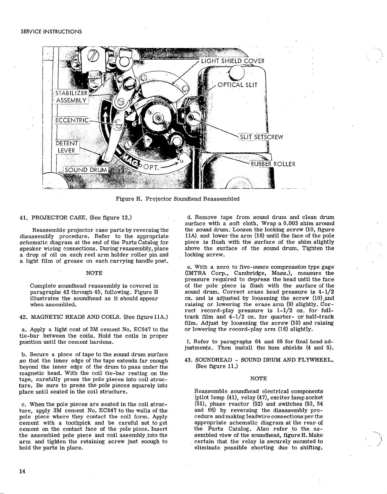
SERVICE
INSTRUCTIONS
l
'_;HT
SHIELD
COVER
OPTICAL
SLIT
:STABILI2ER
ASSEMBLY
ECCENTRIC'
DETENT
LEVER
-1
;SOUND
DRUM
OPT.
SLIT
SETSCREW
RUBBER
ROLLER
Figure
H.
Projector
Soundhead
Reassembled
41.
PROJEC-TOR
CASE.
(See
figure
12.)
Reassemble
projector
case
parts
by
reversing
the
disassembly
procedure.
Refer
to
the
appropriate
schematic
diagram
at
the
end
of
the
Parts
Catalog
for
speaker
wiring
connections.
During
reassembly,
place
a
drop
of
oil
on
each
reel
arm
holder
roller
pin
and
a
light
film
of
grease
on
each
carrying
handle
post.
NOTE
Complete
soundhead
reassembly
is
covered
in
paragraphs
42
through
45,
following.
Figure
H
illustrates
the
soundhead
as
it
should
appear
when
assembled.
42.
MAGNETIC
HEADS
AND
COILS.
(See
figure
11A.)
a.
Apply
a
light
coat
of
3M
cement
No.
EC847
to
the
tie
-bar
between
the
coils.
Hold
the
coils
in
proper
position
until
the
cement
hardens.
b.
Secure
a
piece
of
.tape
to
the
sound
drum
surface
so
that
the
inner
edge
of
the
tape
extends
far
enough
beyond
the
inner
edge
of
the
drum
to
pass
under
the
magnetic
head.
With
the
coil
tie
-bar
resting
on
the
tape,
carefully
press
the
pole
pieces
into
coil
struc-
ture.
Be
sure
to
press
the
pole
pieces
squarely
into
place
until
seated
in
the
coil
structure.
c.
When
the
pole
pieces
are
seated
in
the
coil
struc-
ture,
apply
3M
cement
No.
EC847
to
the
walls
of
the
pole
piece
where
they
contact
the
coil
form.
Apply
cement
with
a
toothpick
and
be
careful
not
to
get
cement
on
the
contact
face
of
the
pole
piece.
Insert
the
assembled
pole
piece
and
coil
assembly, into
the
arm
and
tighten
the
retaining
screw
just
enough
to
hold
the
parts
in
place.
d.
Remove
tape
from
sound
drum
and
clean
drum
surface
with
a
soft
cloth.
Wrap
a
0.003
shim
around
the
sound
drum.
Loosen
the
locking
screw
(10,
figure
11A)
and
lower
the
arm
(16)
until
the
face
of
the
pole
piece
is
flush
with
the
surface
of
the
shim
slightly
above
the
surface
of
the
sound
drum.
Tighten
the
locking
screw.
e.
With
a
zero
to
five
-ounce
compression
type
gage
(IMTRA
Corp.,
Cambridge,
Mass.),
measure
the
pressure
required
to
depress
the
head
until
the
face
of
the
pole
piece
is
flush
with
the
surface
of
the
sound
drum.
Correct
erase
head
pressure
is
4-1/2
oz.
and
is
adjusted
by
loosening
the
screw
10), and
raising
or
lowering
the
erase
arm
(9)
slightly.
Cor-
rect
record
-play
pressure
is
1-1/2
oz.
for
full
-
track
film
and
4-
1
/
2
oz.
for
quarter-
or
half-track
film.
Adjust
by
loosening
the
screw
(10)
and
raising
or
lowering
the
record
-play
arm
(16)
slightly.
f.
Refer
to
paragraphs
64
and
65
for
final
head
ad-
justments.
Then
install
the
hum
shields
(4
and
5).
43.
SOUNDHEAD
-
SOUND
DRUM
AND
FLYWHEEL.
(See
figure
11.)
NOTE
Reassemble
soundhead
electrical
components
(pilot
lamp
(41),
relay
(47),
exciter
lamp
socket
(51),
phase
reactor
(52)
and
switches
(53,
54
and
66)
by
reversing
the
disassembly
pro-
cedure
and
making
leadwire
connections
per
the
appropriate
schematic
diagram
at
the
rear-
of
the
Parts
Catalog.
Also
refer
to
the,
as-
sembled
view
of
the
soundhead,
figure
H.
Make
certain
that
the
relay
is
securely
mounted
to
eliminate
possible
shorting
due
to
shifting.
14
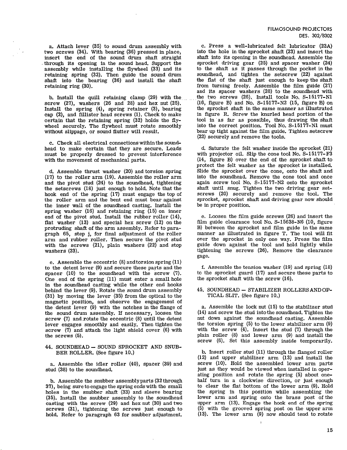
a.
Attach
lever
(35)
to
sound
drum
assembly
with
two
screws
(34).
With
bearing
(36)
pressed
in
place,
insert
the
end
of
the
sound
drum
shaft
straight
_through
its
opening
in
the
sound
head.
Support
the
assembly
while
installing
the
fl
ywheel
(33)
and
its
retaining
spring
(32).
Then
guide
the
sound
drum
shaft
into
the
bearing
(36)
and
install
the
shaft
retaining
ring
(30).
b.
Install
the
quill
retaining
clamp
(29)
with
the
screw
(27),
washers
(26
and
28)
and
hex
nut
(25).
Install
the
spring
(4),
spring
retainer
(3),
bearing
cap
(2),
and
fillister
head
screws
(1).
Check
to
make
certain
that
the
retaining
spring
(32)
holds
the
fly-
wheel
securely.
The
flywheel
must
rotate
smoothly
without
slippage,
or
sound
fl
utter
will
result.
c.
Check
all
electrical
connections
within
the
sound
-
head
to
make
certain
that
they
are
secure.
Leads
must
be
properly
dressed
to
prevent
interference
with
the
movement
of
mechanical
parts.
d.
Assemble
thrust
washer
(20)
and
torsion
spring
(17)
to
the
roller
arm
(19).
Assemble
the
roller
arm
and
the
pivot
stud
(24)
to
the
soundhead,
tightening
the
setscrews
(18)
just
enough
to
hold.
Note
that
the
hook
end
of
the
spring
(17)
must
engage
the
top
of
the
roller
arm
and
the
bent
end
must
bear
against
the
inner
wall
of
the
soundhead
casting.
Install
the
spring
washer
(16)
and
retaining
ring
(15)
on
inner
end
of
the
pivot
stud.
Install
the
rubber
roller
(14),
flat
washer
(13)
and
special
hex
screw
(12)
on
the
protruding
shaft
of
the
arm
assembly.
Refer
to
para-
graph
65,
step
j,
for
final
adjustment
of
the
roller
arm
and
rubber
roller.
Then
secure
the
pivot
stud
with
the
screws
(21),
plain
washers
(22)
and
stop
washers
(23).
e.
Assemble
the
eccentric
(8)
and
torsion
spring
(11)
to
the
detent
lever
(9)
and
secure
these
parts
and
the
spacer
(10)
to
the
soundhead
with
the
screw
(7).
One
end
of
the
spring
(11)
must
enter
a
small
hole
in
the
soundhead
casting
while
the
other
end
hooks
behind
the
lever
(9).
Rotate
the
sound
drum
assembly
(31)
by
moving
the
lever
(35)
from
the
optical
to
the
magnetic
position,
and
observe
the
engagement
of
the
detent
lever
(9)
with
the
notches
in
the
flange
of
the
sound
drum
assembly.
If
necessary,
loosen
the
screw
(7)
and
rotate
the
eccentric
(8)
until
the
detent
lever
engages
smoothly
and
easily.
Then
tighten
the
screw
(7)
and
attach
the
light
shield
cover
(6)
with
the
screws
(5).
44.
SOUNDHEAD
-
SOUND
SPROCKET
AND
SNUB-
BER
ROLLER.
(See
figure
10.)
a.
Assemble
the
idler
roller
(40),
spacer
(39)
and
stud
(38)
to
the
soundhead.
b.
Assemble
the
snubber
assembly
parts
(32
through
37),
being
sure
to
engage
the
spring
ends
with
the
small
holes
in
the
snubber
shaft
(33)
and
sleeve
bearing
(35).
Install
the
snubber
assembly
to
the
soundhead
casting
with
the
screw
(29)
and
hex
nut
(30)
and
two
screws
(31),
tightening
the
screws
just
enough
to
hold.
Refer
to
paragraph
63
for
snubber
adjustment.
FILMOSOUND
PROJECTORS
DES.
302/8302
c.
Press
a
well
-lubricated
felt
lubricator
(23A)
into
the
hole
in
the
sprocket
shaft
(23)
and
insert
the
shaft
into
its
opening
in
the
soundhead.
Assemble
the
sprocket
driving
gear
(25)
and
spacer
washer
(24)
to
the
shaft
as
it
passes
through
the
pocket
in
the
soundhead,
and
tighten
the
setscrew
(22)
against
the
flat
of
the
shaft
just
enough
to
keep
the
shaft
from
turning
freely.
Assemble
the
film
guide
(27)
and
its
spacer
washers
(28)
to
the
soundhead
with
the
two
screws
(26).
Install
tools
No.
S
-15177-N1
(16,
figure
B)
and
No.
S
-15177-N2
(15,
figure
B)
on
the
sprocket
shaft
in
the
same
manner
as
illustrated
in
figure
R.
Screw
the
knurled
head
portion
of
the
tool
in
as
far
as
possible,
thus
drawing
the
shaft
into
the
correct
position.
Tool
No.
S
-15177-N1
must
bear
up
tight
against
the
film
guide.
Tighten
setscrew
(22)
securely
and
remove
the
tools.
d.
Saturate
the
felt
washer
inside
the
sprocket
(21)
with
projector
oil.
Slip
the
cone
tool
No.
S
-15177-F3
(14,
figure
B)
over
the
end
of
the
sprocket
shaft
to
protect
the
felt
washer
as
the
sprocket
is
installed.
Slide
the
sprocket
over
the
cone,
onto
the
shaft
and
into
the
soundhead.
Remove
the
cone
tool
and
once
again
screw
tool
No.
S
-15177-N2
onto
the
sprocket
shaft
until
snug.
Tighten
the
two
driving
gear
set-
screws
(20)
securely
and
remove
the
tool.
The
sprocket,
sprocket
shaft
and
driving
gear
now
should
be
in
proper
position.
e.
Loosen
the
film
guide
screws
(26)
and
insert
the
film
guide
clearance
tool
No.
S
-15638-N6
(10,
figure
B)
between
the
sprocket
and
film
guide
in
the
same
manner
as
illustrated
in
figure
T.
The
tool
will
fit
over
the
sprocket
in
only
one
way.
Press
the
film
guide
down
against
the
tool
and
hold
lightly
while
tightening
the
screws
(26).
Remove
the
clearance
gage.
f.
Assemble
the
tension
washer
(19)
and
spring
(18)
to
the
sprocket
guard
(17)
and
secure
these
parts
to
the
sprocket
shaft
with
the
screw
(16).
45.
SOUNDHEAD
-
STABILIZER
ROLLERS
AND
OP-
TICAL
SLIT.
(See
figure
10.)
a.
Assemble
the
lock
nut
(15)
to
the
stabilizer
stud
(14)
and
screw
the
stud
into
the
soundhead.
Tighten
the
nut
down
against
the
soundhead
casting.
Assemble
the
torsion
spring
(5)
to
the
lower
stabilizer
arm
(9)
with
the
screw
(4).
Insert
the
stud
(7)
through
the
plain
roller
(8)
and
lower
arm
(9)
and
install
the
screw
(6).
Set
this
assembly
inside
temporarily.
b.
Insert
roller
stud
(11)
through
the
fl
anged
roller
(12)
and
upper
stabilizer
arm
(13)
and
install
the
screw
(10).
Hold
the
assembled
lower
arm
parts
just
as
they
would
be
viewed
when
installed
in
oper-
ating
position
and
rotate
the
spring
(5)
about
one-
half
turn
in
a
clockwise
direction,
or
just
enough
to
clear
the
flat
bottom
of
the
lower
arm
(9).
Hold
the
spring
in
this
position
while
assembling
the
lower
arm
and
spring
onto
the
brass
post
of
the
upper
arm
(13).
Engage
the
hook
end
of
the
spring
(5)
with
the
grooved
spring
post
on
the
upper
arm
(13).
The
lower
arm
(9)
now
should
tend
to
rotate
15
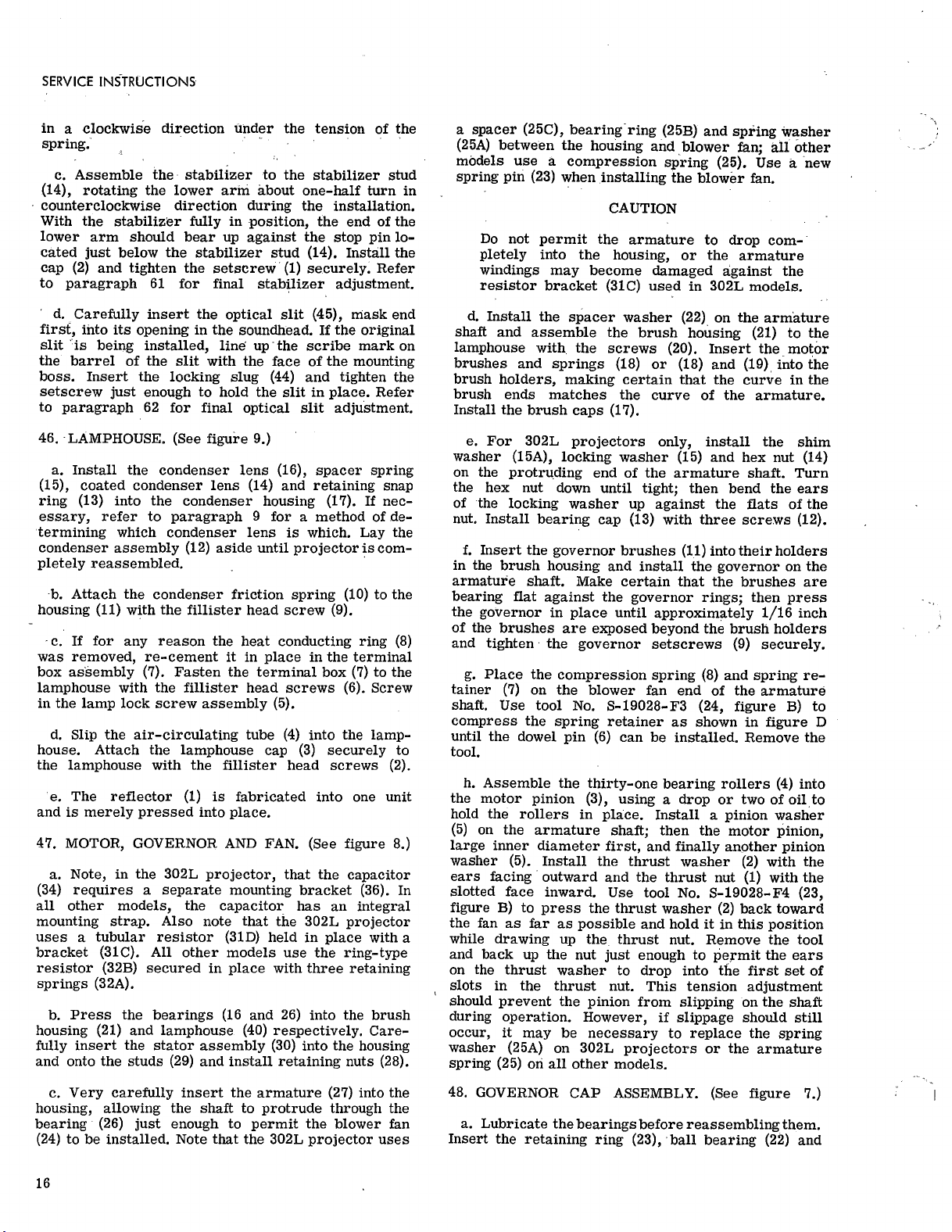
SERVICE
INSTRUCTIONS
in
a
clockwise
direction
under
the
tension
of
the
spring.
c.
Assemble
the
stabilizer
to
the
stabilizer
stud
(14),
rotating
the
lower
arm
about
one-half
turn
in
counterclockwise
direction
during
the
installation.
With
the
stabilizer
fully
in
position,
the
end
of
the
lower
arm
should
bear
up
against
the
stop
pin
lo-
cated
just
below
the
stabilizer
stud
(14).
Install
the
cap
(2)
and
tighten
the
setscrew
(1)
securely.
Refer
to
paragraph
61
for
final
stabilizer
adjustment.
d.
Carefully
insert
the
optical
slit
(45),
mask
end
first,
into
its
opening
in
the
soundhead.
If
the
original
slit
is
being
installed,
line
up
the
scribe
mark
on
the
barrel
of
the
slit
with
the
face
of
the
mounting
boss.
Insert
the
locking
slug
(44)
and
tighten
the
setscrew
just
enough
to
hold
the
slit
in
place.
Refer
to
paragraph
62
for
final
optical
slit
adjustment.
46.
LAMPHOUSE.
(See
figure
9.)
a.
Install
the
condenser
lens
(16),
spacer
spring
(15),
coated
condenser
lens
(14)
and
retaining
snap
ring
(13)
into
the
condenser
housing
(17).
If
nec-
essary,
refer
to
paragraph
9
for
a
method
of
.de-
termining
which
condenser
lens
is
which.
Lay
the
condenser
assembly
(12)
aside
until
projector
is
com-
pletely
reassembled.
b.
Attach
the
condenser
friction
spring
(10)
to
the
housing
(11)
with
the
fillister
head
screw
(9).
c.
If
for
any
reason
the
heat
conducting
ring
(8)
was
removed,
re
-cement
it
in
place
in
the
terminal
box
assembly
(7).
Fasten
the
terminal
box
(7)
to
the
lamphouse
with
the
fillister
head
screws
(6).
Screw
in
the
lamp
lock
screw
assembly
(5).
d.
Slip
the
air
-circulating
tube
(4)
into
the
lamp
-
house.
Attach
the
lamphouse
cap
(3)
securely
to
the
lamphouse
with
the
fillister
head
screws
(2).
e.
The
reflector
(1)
is
fabricated
into
one
unit
and
is
merely
pressed
into
place.
47.
MOTOR,
GOVERNOR
AND
FAN.
(See
figure
8.)
a.
Note,
in
the
302L
projector,
that
the
capacitor
(34)
requires
a
separate
mounting
bracket
(36).
In
all
other
models,
the
capacitor
has
an
integral
mounting
strap.
Also
note
that
the
302L
projector
uses
a
tubular
resistor
(31D)
held
in
place
with
a
bracket
(31C).
All
other
models
use
the
ring
-type
resistor
(32B)
secured
in
place
with
three
retaining
springs
(32A).
b.
Press
the
bearings
(16
and
26)
into
the
brush
housing
(21)
and
lamphouse
(40)
respectively.
Care-
fully
insert
the
stator
assembly
(30)
into
the
housing
and
onto
the
studs
(29)
and
install
retaining
nuts
(28).
c.
Very
carefully
insert
the
armature
(27)
into
the
housing,
allowing
the
shaft
to
protrude
through
the
bearing
(26)
just
enough
to
permit
the
blower
fan
(24)
to
be
installed.
Note
that
the
302L
projector
uses
a
spacer
(25C),
bearing
ring
(25B)
and
spring
washer
(25A)
between
the
housing
and
blower
fan;
all
other
models
use
a
compression
spring
(25).
Use
a
new
spring
pin
(23)
when
installing
the
blower
fan.
CAUTION
Do
not
permit
the
armature
to
drop
com-
pletely
into
the
housing,
or
the
armature
windings
may
become
damaged
against
the
resistor
bracket
(31C)
used
in
302L
models.
d.
Install
the
spacer
washer
(22)
on
the
armature
shaft
and
assemble
the
brush
housing
(21)
to
the
lamphouse
with
the
screws
(20).
Insert
the
motor
brushes
and
springs
(18)
or
(18)
and
(19),
into
the
brush
holders,
making
certain
that
the
curve
in
the
brush
ends
matches
the
curve
of
the
armature.
Install
the
brush
caps
(17).
e.
For
302L
projectors
only,
install
the
shim
washer
(15A),
locking
washer
(15)
and
hex
nut
(14)
on
the
protruding
end
of
the
armature
shaft.
Turn
the
hex
nut
down
until
tight;
then
bend
the
ears
of
the
locking
washer
up
against
the
flats
of
the
nut.
Install
bearing
cap
(13)
with
three
screws
(12).
f.
Insert
the
governor
brushes
(11)
into
their
holders
in
the
brush
housing
and
install
the
governor
on
the
armature
shaft.
Make
certain
that
the
brushes
are
bearing
flat
against
the
governor
rings;
then
press
the
governor
in
place
until
approximately
1/16
inch
of
the
brushes
are
exposed
beyond
the
brush
holders
and
tighten
the
governor
setscrews
(9)
securely.
g.
Place
the
compression
spring
(8)
and
spring
re-
tainer
(7)
on
the
blower
fan
end
of
the
armature
shaft.
Use
tool
No.
S
-19028-F3
(24,
figure
B)
to
compress
the
spring
retainer
as
shown
in
figure
D
until
the
dowel
pin
(6)
can
be
installed.
Remove
the
tool.
h.
Assemble
the
thirty-one
bearing
rollers
(4)
into
the
motor
pinion
(3),
using
a
drop
or
two
of
oil
to
hold
the
rollers
in
place.
Install
a
pinion
washer
(5)
on
the
armature
shaft;
then
the
motor
pinion,
large
inner
diameter
first,
and
finally
another
pinion
washer
(5).
Install
the
thrust
washer
(2)
with
the
ears
facing
outward
and
the
thrust
nut
(1)
with
the
slotted
face
inward.
Use
tool
No.
S
-19028-F4
(23,
figure
B)
to
press
the
thrust
washer
(2)
back
toward
the
fan
as
far
as
possible
and
hold
it
in
this
position
while
drawing
up
the
thrust
nut.
Remove
the
tool
and
back
up
the
nut
just
enough
to
permit
the
ears
on
the
thrust
washer
to
drop
into
the
first
set
of
slots
in
the
thrust
nut.
This
tension
adjustment
should
prevent
the
pinion
from
slipping
on
the
shaft
during
operation.
However,
if
slippage
should
still
occur,
it
may
be
necessary
to
replace
the
spring
washer
(25A)
on
302L
projectors
or
the
armature
spring
(25)
on
all
other
models.
48.
GOVERNOR
CAP
ASSEMBLY.
(See
figure
7.)
a.
Lubricate
the
bearings
before
reassembling
them.
Insert
the
retaining
ring
(23),
ball
bearing
(22)
and
16

into
F
I
FILMOSOUND
PROJECTORS
DES.
302/8302
retaining
ring
(21)
into
the
governor
cap
(25).
Insert
the
shaft
(20)
through
the
ball
bearing.
Reach
in
from
the
opposite
side
of
the
governor
cap
and
press
the
retaining
pin
(19)
the
hole
provided
in
the
shaft.
Insert
the
worm
wheel
(18),
ball
bearing
(17)
and
retaining
washer
(16),
and
secure
these
parts
in
place
with
the
truss
head
screw
(15).
b.
Place
eighteen
bearing
rollers
(14)
around
the
inner
diameter
of
the
rear
take-up
pulley
(13).
Be
sure
to
lubricate
the
rollers
with
B
&
H
grease
before
reassembling
them.
Insert
the
clutch
ball
retainer
(12)
into
the
take-up
pulley.
c.
Position
the
clutch
cam
(10)
on
the
shaft
with
the
slot
in
the
cam
engaging
the
ear
on
the
clutch
ball
retainer.
When
the
clutch
cam
(10)
has
been
placed
properly,
the
small
ends
of
the
three
cutouts
in
the
outer
edge
will
be
in
a
clockwise
direction
from
the
large
ends
of
the
cutouts.
d.
Insert
the
three
steel
balls
(11)
in
between
the
ears
on
the
outside
diameter
of
the
retainer
and
then
place
the
compression
spring
(9)
in
the
slot
in
the
cam.
Install
the
bronze
washer
(8),
reel
drive
clutch
cover
(7)
and
screw
(6).
Use
special
tool
No.
S
-12264-F3
(25,
figure
B)
to
screw
in
the
screw
(6).
d.
Insert
the
worm
shaft
(4)
through
the
felt
washer
(5)
and
governor
cap
(25).
Install
the
radial
bearing
(3)
and
screw
in
the
fillister
head
screw
(2).
Lubri-
cate
the
radial
bearing
and
pack
the
space
between
the
bearing
and
the
nut
(1)
with
a
liberal
amount
of
B
&
H
grease.
1.
Screw
on
t
he
special
nut
(1)
with
a
pair
of
long
nosed
pliers.
49.
BLOWER
HOUSING.
(See
figure
6.)
a.
Assemble
the
lens
(11)
into
the
condenser
holder
(14)
with
the
retaining
ring
(10).
Note
that
the
302L
projector
condenser
assembly
has
a
one-piece
holder
and
handle;
on
all
other
projectors,
the
handle
(13)
is
removable.
b.
If
the
spring
retainer
(7)
was
removed
for
re-
placement,
fasten
the
new
retainer
in
place
with
two
No.
2-56
NC
by
1/4
inch
round
head
screws
and
hex
nuts
in
place
of
the
rivets
originally
used.
c.
For
302L
projectors
only,
attach
the
fire
shutter
guide
to
the
blower
housing
with
two
screws
(2).
Engage
the
bent
ear
of
the
fire
shutter
assembly
(1)
with
the
slot
in
the
guide
and
temporarily
secure
the
fire
shutter
with
a
piece
of
tape.
Refer
to
para-
graph
59
for
fire
shutter
adjustment.
d.
For
all
projectors
except
the
302L,
engage
the
bent
ends
of
the
heat
filter
pivot
(16)
with
the
upper
pair
of
holes
in
the
heat
filter
assembly
(18).
Assem-
ble
the
heat
filter
to
the
filter
mounting
plate
(17)
and
bend
the
ears
of
the
mounting
plate
so
that
the
notches
in
the
ears
engage
the
bent
ends
of
the
pivot
(16).
Fasten
the
pivot
and
mounting
plate
to
the
blower
housing
with
the
screw
(15).
Assemble
the
filter
actuating
crank
(20)
through
the
hole
in
the
blower
housing
and
insert
the
end
of
the
crank
through
the
loops
of
the
actuating
link
(19).
Engage
the
bent
ends
of
the
link
with
the
lower
pair
of
holes
in
the
heat
filter
(18).
Operate
the
crank
to
check
heat
filter
operation.
50.
GEAR
CASE
-
SHUTTER
AND
SHUTTLE.
(See
figure
5.)
NOTE
All
302L
projectors
are
of
the
permanently
-
lubricated
type
as
evidenced
by
the
lack
of
oil
cups
on
the
top
of
the
gear
case.
Some
302M
and
8302
models,
however,
will
be
of
the
oil
cup
design
and,
in
addition
to
the
oil
cups
in
the
top
of
the
gear
case,
will
include
the
special
oiler
assembly
(31).
Refer
to
paragraph
22
for
proper
lubricating
instructions
and
lubricants.
See
figure
U
for
proper
position-
ing
of
oil
cup
tubes.
a.
Install
the
same
quantity
of
bearing
shims
(29)
on
the
bearings
(28)
as
were
removed
in
disassembly
and
press
the
bearings
into
the
gear
case
(35).
NOTE
Before
replacing
shaft
bearings
(28),
note
that
there
is
a
hole
drilled
in
the
barrel
of
each
one.
These
holes
must
line
up
with
the
ends
of
the
hole
that
is
provided
in
the
gear
case
for
oiler
felt
(27),
so
that
ends
of
the
oiler
felt
will
continually
lubricate
shuttle
shaft
(13)
and
counter
gear
shaft
(22).
b.
Saturate
oiler
felt
(27)
with
B
&
H
oil.
Replace
oiler
felt
(27)
by
inserting
it
into
one
of
the
shaft
bear-
ings
and
then
forcing
it
into
hole
that
extends
between
the
two
shaft
bearings.
Attach
spring
clamp
(26)
be-
tween
the
two
shaft
bearings
with
flat
head
screw
(25).
c.
Saturate
oiler
assembly
(31)
with
B&
H
oil
and
at-
tach
it
inside
gear
case
with
fillister
head
screw
(30).
d.
In
order
to
reassemble
shafts
(22
and
13),
bearings
(23
and
14)
and
felts
(24
and
15)
correctly
and
easily,
the
following
directions
should
be
read
and
followed
carefully.
Figures
J
through
N
will
help
by
illustrating
the
various
steps.
e.
Place
the
tool
jig
No.
S
-4007-F11
(7,
figure
B)
on
the
table
in
front
of
you.
Slide
the
brass
sleeve
No.
S
-4007-F5
(5,
figure
B)
over
the
post
on
the
jig.
Now
slide
collar
No.
S
-4007-F6
(9,
figure
B)
over
the
brass
sleeve,
being
sure
the
cone
surface
of
the
collar
is
facing
up.
Place
fifteen
new
steel
balls
(23)
on
the
cone
surface
as
shown
in
figure
J.
Do
not
grease
the
steel
balls.
Then
place
the
counter
gear
and
shaft
assembly
(22)
inside
the
brass
sleeve
in
the
same
manner
as
shown
in
figure
K
for
the
shuttle
shaft.
Slide
the
collar
on
which
the
steel
balls
are
resting
up
along
the
brass
sleeve
and
note
the
17
This manual suits for next models
1
Table of contents
Other Bell&Howell Projector manuals


