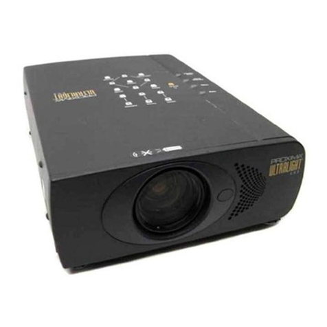
Bell&Howell 614CB Operating instructions

Disclaimer
This scanned document is provided as a courtesy. We make
no representation for its accuracy. It is for use by qualified
personnel only. There are high voltage and mechanical
hazards present in this equipment. Do not attempt repair
unless you are fully aware of the safety precautions to be
taken. Use this information at your own risk.
www.paulivester.com


TABLE
OF
CONTENTS
Paragraph
INTRODUCTION
SPECIFICATION
DATA
DISASSEMBLY
PROCEDURE
Page
3
3
4
1.
Special
Tools
4
3.
Removal
of
Major
Components
4
11,
Feed
-Reel
--Arm
Assembly
5
-
Take-up
Reel
Arm
Assembly
5
13.
Switch
Plate
Assembly
5
14,
Sound
Head
-
614CB
Only
5
(Refer
to
para.
29
for
614CBM
and
CBRM
sound
head)
15.
Jockey
Roller
Assembly
6
16.
Impedance
Roller
Assembly
6
17,
Stabilizer
Housing
Assembly
6
18,
Universal
Drive
Motor
6
(Refer
to
para.
92
for
synchronous
motor
repair)
19.
Drive
Motor
Gear
Housing
7
20,
Blower
Motor
Assembly
7
21,
Rear
Mechanism
Plate
7
22.
Feed
and
Take-up
Pulleys
7
23,
Aperture
Plate
Assembly
7
24..
Lens
Holder
Assembly
7
25,
Lens
Mounting
Assembly
7
26,
Sprockets,
Sprocket
Guards
and_Gears
7
27,
Loopsetter
Adjusting
Assembly
-
8
28.
Shutter
and
Shuttle
Mechanism
8
29.
Sound
Head
-
614CBM
and
CBRM
8
30,
Projector
Case
9
31.
Amplifier
and
Speaker
9
CLEANING
AND
REPAIR
9
REASSEMBLY
PROCEDURE
10
35.
Feed
Reel
Arm
Assembly
10
36,
Take-up
Reel
Arm
Assembly
10
37,
Jockey
Roller
Assembly
10
38,
Impedance
Roller
Assembly'
10
39.
Stabilizer
Housing
Assembly
10
40,
Sound
Head
-
614
CB
only
11
(Refer
to
para.
51
for
614CBM
and
CBRM
sound
head)
41.
Drive
Motor
Gear
Housing
.
.. . . . . . . . . .
•
. . . . . .
12
42,
Universal
Drive
Motor
.,.
. .
-
. . . . .
.‘„
. . . . . .
•
•
12
(Refer
to
para.
92
for
synchronous
motor
repair)
43.
Blower
Motor
Assembly
12
44.
Rear
Mechanism
Plate
12
45,
Feed
and
Take-up
Pulleys,
13
46,
Aperture
Plate
Assembly
13
47,
Lens
Holder
Assembly
13
48,
Loopsetter
Adjusting
Assembly
13
49,
Sprockets,
Sprocket
Guards
and
Gears
13
50.
Shutter
and
Shuttle
Mechanism
S
14
51,
Sound
Head
-
614
CBM
and
CBRM
15
52.
Installation
of
Major
Components
16
63,
Adjusting
Shuttle
and
Aperture
Plate
Mounting
Bracket
...... .
18
64,
Adjusting
Film
Perforation
Clearance
19
65,
Synchronizing
Lower
Film
Sprockets
. . . . . . . . . . . . . . .
9
,
19
1

Paragraph
Page
66.
Film
Take-up
Tension
Adjustment
19
67.
Loopsetter
Adjusting
Assembly
Adjustment
20
TEST
PROCEDURE
21
68.
Localizing
Common
Sound
Troubles
21
72.
Amplifier
Trouble
Analysis
23
79.
Localizing
Loudspeaker
Troubles
24
80.
Projector
Set
Characteristics
Tests
24
81.
Sound
Optical
System
Alinement
Tests
24
87.
Checking
Photocell
Output
26
Table
I.
Projector
Circuit
Voltages
27
Table
II.
Tube
and
Output
Transformer
Measurements
27
Table
HI.
Amplifier
Trouble
Analysis
Chart
29
Table
IV.
D
-C
Supply
Voltage
-Drop
Measurements
32
Table
V.
D
-C
Resistance
Measurements
32
Table
VI.
A
-C
Voltage
Measurements
32
Table
VII.
Projector
Characteristics
Tests
33
Table
VIII.
Amplifier
Characteristics
Tests
36
Table
IX.
Loudspeaker
Characteristics
Tests
38
TROUBLE
SHOOTING
CHART
46
AUTHORIZED
MODIFICATION
KITS
55
88.
Installing
Hour
Counter
Kit
55
89.
Counter
Drive
Mechanism
Repair
55
90.
Installing
48
-Frequency
Shutter
Kit
56
91.
Converting
from
Universal
to
Synchronous
Drive
Motor
56
92.
Synchronous
Drive
Motor
Repair
57
DESIGN
614CD
MAINTENANCE
58
***
.
P
tttittts
•4
4.4
.4•
fttte
(
Figure
1.
Design
614
CB
Projector
—
Overall
View
2

This
manual
has
been
prepared
to
aid
in
serv-
icing
the
Bell
&
Howell
Design
614
16
-mm
Projector.
Complete
instructions
for
the
disassembly,
cleaning,
repair,
reassembly
and
adjustment
of
the
projector
are
given
in
a
step-by-step
fashion.
An
illustrated
parts
catalog
section
is
included
at
the
rear
of
the
manual
to
identify
replacement
parts
for
ordering
purposes.
The
exploded
view
illustrations
in
the
parts
catalog
section
have
been
indexed
in
order
of
disassembly.
The
serviceman
must
use
his
own
judgment
in
eli-
minating
unnecessary
steps
of
disassembly
when
making
certain
definite
repairs.
Four
models
of
the
projector
are
covered
in
this
book
—
614CB,
614CBM,
614CBRM
and
614CD.
The
614CD
is
a
commercial
version
of
the
projector
pre-
sently
being
supplied
to
the
Armed
Forces.
Although
all
four
projectors
are
very
similar
in
design
and
construction,
the
614CD
is
outwardly
distinguished
by
its
twin
line
'fuses
(top
front
of
projector
case),
fabric
drive
belts
with
adjustable
tension
rollers,
lifetime
lubrication
system
and
newly
designed
case
legs.
Except
when
specifically
noted,
the
general
repair.
instructions
contained
herein
will
apply
to
all
four
models,
with
minor
differences
illustrated
in
the
Parts
Catalog
exploded
views
by
means
of
insets.
Wiring
schematics
and
the
more
complicated
repairs
and
ad-
justments
which
are
applicable
only
to
the
614CD
will
be
found
in
the
addendum
beginning
on
page
58.
The
quality
of
service
work
performed
will
de-
pend,
to
a
large
extent,
upon
the
ability
and
in-
genuity
of
the
serviceman.
Be
sure
to
use
the
proper
tools
during
actual
disassembly
and
reassembly
pro-
cedures,
and
be
careful
not
to
scratch
or
mar
the
equipment.
During
disassembly
of
the
equipment,
observe
and
remember
the
manner
in
which
each
part
is
installed.
When
a
part
has
been
removed,
reinstall
its
attaching
screws
into
their
tapped
holes
to
prevent
loss
and
mix-up.
Take
particular
care
when
reassembling
the
pro-
jector.
The
customer
expects
his
equipment
to
look
and
operate
like
new
when
it
is
returned.
Touch
up
marred
surfaces
with
matching
paint
(B
-H
SPEC
No.
1148).
LUBRIC
ANTS.
Due
to
the
nature
of
the
design
of
these
pro-
jectors,
it
is
imperative
that
only
the
following
lubricants
be
used:
Oil
—
Bell
&
Howell
Stock
No.
611753
Grease
—
Standard
Oil
"Stanolith
No.
42"
Internal
lubrication
for
the
614CB,
614CBM
and
614CBRM
projectors
is
supplied
through
a
one
-point
feed
lubrication
system.
Oil
is
applied
to
the
central
oil
well
cup
on
top
of
the
projector
case
and
is
fed
through
oil
tubing
to
all
bearings
and
to
the
inter-
mittent
mechanism
reservoir.
In
614CD
projectors,
the
oil
well
cup
and
tubing
have
been
removed.
A
felt
pad
below
the
shutter
and
shuttle
camshafts
is
satura-
ted
with
oil
and
feeds
all
parts
of
the
intermittent
mechanism
through
a
system
of
felt
wicks.
Refer
to
the
addendum
sheets
beginning
on
page
58
for
wick
re-
placement.
CAUTION:
Before
returning
a
repaired
614CB,
614CBM
or
614CBRM
projector
to
customer,
be
sure
to
fill
the
oil
well
cup
with
4
cc
of
oil
and
caution
customer
to
check
oil
level
before
operation.
SPECIFICATION
DATA
Film
size
16
-mm
Film
reel
capacity
2000
ft.
Film
speed
(CB
and
CBM)
16
and
24
fps
Film
speed
(CBRM
and
CD)
24
fps
Power
supply
105-129
volts,
50-60
cycles
Power
consumption
1300
watts
Projector
lamp
(25
hr.
life)
. . .
1000
watt,
115
-volt
Exciter
lamp
6
-volt,
1
-amp
Threading,
lamp
120
-volt,
6
-watt
Photocell
(614CB,
CBM,
CBRM)
. .
Lead
sulphide
Photocell
(614CD)
germanium
diode
Projector
fuse
(1
req'd)
15
amp
Amplifier
fuse(2
req'd
for
614CD)0.8
amp,
slow
-blow
Drive
motor
(CB,
CBM,
and
CD)
. .
universal
type
with
centrifugal
governor
Drive
motor
(CBRM)
synchronous
type
Ventilation
24
-blade,
motor
driven,
3
in.
diam.
rotor
Amplifier
input
Power
output
Sound
head
output
Tube
complement
0.4
volts
8
watts
high
impedance
(projector
amplifier):
(2)
12AX7,
(2)
6x4,
and
(3)
6AQ5
Tube
complement
(record
amplifier):
(2)
12AX7,
(1)
6x4,
(3)
12AU7
Overall
dimensions,
complete
projector:
14-1/2
in.
high,
12-1/8
in.
wide,
16-1/4
in.
long
Approxithate
weight
48
lbs.
3

naiddeApteev
Am
-acne
1.
SPECIAL
TOOLS.
The
special
tools
illustrated
in
figure
2
are
re-
quired
to
perform
the
overhaul
procedures
outlined
in
this
handbook.
Refer
to
the
key
to
figure
2
for
proper
part
number
and
nomenclature
of
tools.
2.
GENERAL
OVERHAUL
INSTRUCTIONS.
The
following
procedures
provide
for
the
com-
plete
disassembly
of
the
projector,
with
each
of
its
major
components
treated
separately.
Before
per-
forming
all
of
the
steps
in
the
disassembly
sequence,
first
attempt
to
localize
the
trouble
by
analyzing
the
customer's
report
with
reference
to
the
trouble
shoot-
ing
chart,
the
amplifier
trouble
analysis
chart
(Table
III)
and
the
equipment
characteristics
tests
(Tables
VII,
VIII
and
DC):
If
a
complete
overhaul
of
equipment
is
indicated,
perform
the
operations
specified
in
the
following
paragraphs.
Refer
to
the
exploded
views
for
disassembly
of
miscellaneous
parts.
3.
REMOVAL
OF
MAJOR
COMPONENTS.
NOTE:
Refer
to
the
projector
operation
book
for
in-
structions
pertinent
to
the
removal
of
such
items
as
the
reel
arms,
pressure
plate,
aperture
plate,
con-
denser
lens
assembly,
projection
lamp
parts,
etc.
4.
AMPLIFIER
AND
SPEAKER
ASSEMBLY.
(See
Parts
Catalog
figure
1.)
The
amplifier
housing
is
secured
to
the
projector
case
by
six
screws
(23)
and
lock
washers
(24)
located
at
the
top,,
front
and
bottom
of
the
case
and
three
screws
(25)
and
lock
washers
(26)
which
also
serve
to
fasten
one
edge
of
the
switch
plate
(30)
to
the
amplifier
case.
Remove
these
screws
and
carefully
pull
the
amplifier
away
from
the
pro-
jector
case
until
the
leadwires
are
exposed.
Dis-
connect
leadwires
as
required,
and
separate
the
amplifier
assembly
from
the
projector
case.
5.
SWITCH
PLATE
ASSEMBLY.
(See
Parts
Catalog
figure
1.)
Remove
screws
(28),
lock
washers
(29)
and
junction
box
front
plate
(27).
Remove
screws
(33
and
34),
elastic
cam
lock
stop
nuts
(35)
and
cable
clamp
(36)
to
free
junction
box.
Unsolder
fuseholder
and
re-
ceptacle
leadwires
within
the
junction
box.
Note
wiring
harness
connections
to
various
projector
corn-
,
ponents.
Two
small,
shielded
wires
from
sound
head
assembly
must
be
disconnected
at
the
OFF
-MOTOR
-
LAMP
switch
and
unwound
from
harness.
The
ground
terminal
at
one
end
of
large,
shielded
harness
is
fastened
to
mechanism
plate
just
behind
projection
lamp
socket.
Two
leadwires
must
be
disconnected
from
the
lampholder
behind
the
junction
box.
The
5-061081-N15
■
e
5-061000-F1
o
S
-061081-N8
5-063196-N2
S
-061081-N31
5-061081-N16
e
e
-5-061082-N1
S
-061081-N6
S
-061020-N3
43.
-S-061020-N10
SURFACE
PLATE
(NOT
SUPPLIED)
Part
No.
Description
-,_Part
No.
Description
S
-061000-F1
Sound
optical
tool
S
-061081-N31
Sprocket
synchronizing
gage
S
-061020-N10
Master
block
and
plate
S
-061081-N6
Shuttle
alinement
gage
S
-061020-N3
Front
cam
shaft
indicator
gage
S
-061081-N8
Shutter
protrusion
gage
S
-061081-N15
Shutter
and
intermittent
gage
S
-061082-N1
Sound
drum
positioning
gage
S
-061081-N16
Sprocket
film
clearance
gage
S
-063196-N2
Aperture
guide
rail
gage
Figure
2.
Special
Service
Tools
Required.
4

lb;
two
blower
motor
leadwires
must
be
disconnected
at
the
OFF
-MOTOR
-LAMP
switch.
Remove
three
switch
plate
screws
(31)
and
lock
washers
(32),
and
carefully
lift
complete
switch
plate
assembly
(30),
with
wiring
harness,
from
projector.
6.
FRONT
AND
REAR
MECHANISM
PLATE.
(See
Parts
Catalog
figure
2.)
a.
Loosen
special
hex
nut
(13)
and
remove
loopsetter
knob
(14)
from
loopsetter
rod.
b.
Remove
flywheel
retaining
screw
(8)
and
care-
fully
remove
flywheel
(7)
from
stabilizer
shaft.
c.
Check
all
leadwires
and
cables,
loosening
any
cable
clamps
or
freeing
any
leadwire
terminals
that
might
prevent
removal
of
the
mechanism
plate.
d.
Remove
two
binding
head
screws
(16)
and
lock
washers
(17)
and
two
hex
head
screws
(26),
lock
washers
(27)
and
flat
washers
(28)
that
secure
the
mechanism
plate
at
the
four
vibration
mounts.
e.
Remove
mechanism
plate
(15)
through
the
door
side
of
the
projector
—not
through
the
amplifier
opening.
7.
DRIVE
MOTOR
ASSEMBLY.
(See
Parts
Catalog
figure
6.)
Loosen
set
screw
(14)
and
remove
threading
knob
(13).
Loosen
the
two
screws
in
the
idler
roller
bracket
at
the
top
of
the
drive
motor,
and
shift
bracket
to
the
right
to
remove
tension
from
drive
chain
(24).
Disengage
chain
from
sprocket
above
motor.
Remove
four
screws
(21),
lock
washers
(22)
and
plain
washers
(23),
supporting
the
drive
motor
to
prevent
it
from
falling.
Carefully
remove
drive
motor,
disengaging
drive
chain
from
flexible
drive
coupling.
8.
FEED
AND
TAKE-UP
PULLEY
ASSEMBLIES.
(See
Parts
Catalog
figure
16.)
Loosen
two
screws
(29)
so
that
idler
assembly
(28)
can
be
shifted
to
the
right,
thereby
removingtension
from
drive
chain
(19).
Slip
drive
chain
from
sprockets
(17,
20
and
24).
Loosen
set
screws
(21
and
25),
and
remove
sprockets
(20
and
24),
pulleys
(22
and
26)
and
thrust
washers
(23
and
27)
from
mechanism
plate.
9.
LENS
HOLDER
ASSEMBLY.
(See
Parts
Catalog
figure
16.)
Remove
two
screws
(43),
lock
washers
(44)
and
the
lens
holder
stop
plate
(42).
Slowly
rack
the
lens
holder
assembly
(45)
forward
by
turning
the
knurled
focusing
knob
on
the
lens
mounting
assembly
(49)
until
the
lens
holder
assembly
is
free.
Be
careful
not
to
lose
the
friction
button
(46)
and
friction
spring
(47)
located
in
a
recess
in
the
mounting
assembly.
10.
LENS
MOUNTING
ASSEMBLY.
(See
Parts
Cata-
log
figure
16.)
Remove
three
screws
(50
and
51)
and
one
lock
washer
(52)
and
lift
the
lens
mounting
as-
sembly
(49)
from
the
mechanism
plate.
Invert
mount-
ing
assembly
and
permit
guide
disc
(48)
to
drop
into
hand.
11.
FEED
REEL
ARM
ASSEMBLY.
(See
Parts
Catalog
figure
3.)
a.
Remove
nuts
(3
and
4)
and
spring
(5).
b.
Tap
out
the
driving
pin
(6)
and
remove
spindle
clutch
assembly
(7),
clutch
plate
subassembly
(8),
and
thrust
washer
(10).
If
necessary,
press
ball
bearing
(9)
from
clutch
plate
subassembly.
c.
Remove
spindle
assembly
(2),
spindle
pulley
(11)
and
friction
washer
(12)
from
arm
(15).
If
necessary,
press
thrust
bearings
(14)
from
arm.
d.
Inspect
parts
for
actual
physical
damage.
Press
bearings
onto
wooden
dowels
of
snug
fit
and
spin
the
bearing,
noting
any
roughness
in
rotation
which
would
indicate
bearing
balls
or
rollers
with
flat
spots.
Replace
damaged
parts.
12.
TAKE-UP
REEL
ARM
ASSEMBLY.
(See
Parts
Catalog
figure
4.)
a.
Remove
elastic
stop
nut
(3),
tension
nut
(4)
and
tension
spring
(5).
b.
Tap
out
driving
pin
(6)
and
disassemble
remaining
parts
from
take-up
arm
(14).
c.
Inspect
parts
for
actual
physical
damage.
Press
the
bearings
onto
wooden
dowels
of
snug
fit
and
spin
the
bearing,
noting
any
roughness
in
rotation
which
would
indicate
bearing
balls
or
rollers
with
flat
spots.
Replace
all
damaged
parts.
13.
SWITCH
PLATE
ASSEMBLY.
(See
Parts
Catalog
figure
5.)
Under
normal
circumstances,
complete
disas-
sembly
of
the
switch
panel
will
not
be
necessary.
Re-
moval
of
parts
for
replacement
can
be
accomplished
by
reference
to
Parts
Catalog
figure
5.
14.
SOUND
HEAD
ASSEMBLY-614CB
ONLY.
(See
Parts
Catalog
figure
7.)
NOTE:
Refer
to
paragraph
29
for
disassembly
of
sound
head
for
614CBM
and
CBRM
projectors.
a.
Remove
retaining
rings
(3)
and
washers
(4)
and
pull
roller
assemblies
(1
and
2)
from
pivot
studs
(5).
Refer
to
paragraph
15
for
repair
instructions
for
these
roller
assemblies.
b.
Remove
screw
(8)
and
impedance
roller
assembly
(7).
Refer
to
paragraph
16
for
impedance
roller
re-
pair
instructions.
c.
Loosen
set
screws
(10
and
11)
and
carefully
with-
draw
stabilizer
housing
assembly
(9).
Refer
to
para-
graph
17
for
repair
instructions
for
housing
assembly.
d.
Loosen
cover
screw
(13)
and
remove
lamp
cover
assembly
(12).
Move
pin
release
cam
(18)
to
extreme
right-hand
position,
and
lift
out
the
exciter
lamp
(16).
Lamp
socket
parts
can
be
disassembled
by
removing
lamp
socket
nut
(17),
screw
(20)
and
lock
washer
(21),
and
three
flat
head
screws
(23).
CAUTION
The
scanning
lens
(24)
is
pre-set
by
means
of
precision
instruments
for
maximum
efficiency
and
should
not
be
disturbed
-
unless
it
has
been
determined
that
this
item
requires
replace-
ment.
If
such
is
the
case,
remove
screw
(25)
and
withdraw
the
lens.
e.
Loosen
knob
on
photocell
cover
assembly
(26)
and
lift
off
the
cover.
To
remove
photocell
assembly
5

(37),
take
out
screws
(38)
and
lock
washers
(39)
and
disconnect
cell
leadwire
lugs
from
terminal
block
(30).
f.
Remove
screws
(31
and
34)
and
lock
washers
(32)
to
free
terminal
block
(30).
Note
spacing
collar
(33)
between
terminal
block
and
casting
and
hexagonal
spacer
nut
(35)
at
front
of
terminal
block.
Disas-
semble
remaining
parts
as
required.
g.
Replace
all
damaged
parts.
Photocell
assembly
replacement
is
determined
by
analyzing
the
accom-
panying
customer
report
for
the
projector
and
by
pre-
testing
the
equipment
as
instructed
in
the
Test
Pro-
cedure
section,
page
21.
15.
JOCKEY
ROLLER
ASSEMBLY.
(See
Parts
Catalog
figures
8
and
9).
NOTE:
Both
the
upper
jockey
roller
assembly
and
lower
jockey
roller
assembly
are
covered
by
the
following
instructions.
Except
for
the
difference
in
roller
housings,
both
assemblies
are
identical
in
construction.
a.
Loosen
set
screw
(2)
and
pull
out
roller
shaft
(3),
thus
freeing
all
parts
of
assembly.
Do
not
press
bearings
(1
and
4)
from
housing
(6)
unless
damaged.
b.
Inspect
roller
for
deep
scratches,
nicks
or
flat
spots.
Inspect
shaft
for
bends
and
make
certain
that
shaft
bearing
surfaces
are
not
rough.
Check
housing
for
rough
spots
which
might
interfere
with
free
ro-
tation
of
roller.
16.
IMPEDANCE
ROLLER
ASSEMBLY.
(See
Parts
Catalog
figure
10.)
a.
Loosen
set
screws
(1
and
2)
and
unscrew
the
ad-
justable
pivot
pin
(4).
The
slug
(3)
will
drop
into
the
housing
(12)
as
pivot
pin
is
withdrawn.
Remove
plain
pivot
pin
(5)
and
li
ft
roller
(6)
from
housing.
b.
Disassemble
parts
(7)
through
(11)
from
hous-
ing
(12).
c.
Inspect
pivot
pins
(4
and
5)
to
make
certain
that
tapered
ends
are
not
blunted
or
distorted.
Check
spring
for
broken
ends.
Make
certain
that
bearings
in
roller
are
free
of
dirt,
dust
or
other
foreign
sub-
stance.
Inspect
roller
for
deep
scratches,
nicks
or
flat
spots.
17.
STABILIZER
HOUSING
ASSEMBLY-
CB,
CBM,
and
CBRM
only.
(See
Parts
Catalog
figure
11.)
CAUTION
Unless
the
tools
mentioned
in
paragraph
39,
step
g,
are
available,
do
not
attempt
to
dis-
assemble
the
film
scanning
drum
(2)
and
shaft
(14)
from
the
stabilizer
housing.
a.
Hold
lock
nut
(10)
with
wrench
and
carefully
remove
sound
drum
nut
(1).
Pull
film
scanning
drum
(2)
from
shaft
(14).
b.
Remove
screws
(6)
and
carefully
lift
brackets
(5),
prism
mount
(8)
and
light
pipe
prism
(7)
from
housing
(15).
Lift
the
prism
gently
from
the
mount.
c.
Remove
screws
(12)
and
pull
assembled
shaft
(14)
from
housing.
Place
wrench
on
flats
of
shaft,
unscrew
self
locking
nut
(9).
Unscrew
lock
nut
(10)
and
remove
lock
plate
(11)
and
bearing
(13)
from
shaft.
Remove
bearing
(3)
and
thrust
washer
(4)
from
housing.
CAUTION
Avoid
placing
fingers
on
ball
races
of
bearing
during
removal,
and
do
not
use
any
tool
that
might
cause
damage
to
bearing.
After
removal,
wrap
bearing
in
clean
cloth
or
tin
foil.
d.
Prism
should
be
wiped
with
soft
lint
-free
cloth.
Inspect
prism
for
chips,
scratches
or
discolora-
tion.
Inspect
film
scanning
drum
for
nicks
or
grooves.
Make
certain
that
stabilizer
shaft
is
not
bent
in
any
way.
Check
ball
bearing
rotation;
bearings
should
ro-
tate
freely
and
smoothly.
18.
UNIVERSAL
DRIVE
MOTOR
ASSEMBLY.
(See
Parts
Catalog
figure
12.)
NOTE:
Refer
to
paragraph
92
for
synchronous
mo-
tor
repair.
a.
Remove
resistor
and
mounting
bracket
parts
(items
1
through
7)
and'
capacitors
(8
and
30)
from
motor
housing,
unsoldering
leadwires
as
required.
b.
In
order
to
remove
motor
gear
housing
assembly
(11),
it
first
will
be
necessary
to
remove
the
flexible
coupling
from
the
gear
housing
shaft.
This
can
be
done
by
loosening
the
coupling
set
screw
closest
to
the
end
of
the
shaft
and
sliding
off
the
coupling
with
attached
chain
sprocket.
Take
out
three
screws
(12
and
14)
and
lock
washers
(13
and
15)
and
withdraw
the
com-
plete
gear
housing.
Temporarily
assemble
coupling
to
shaft
and
set
this
assembly
aside.
Repair
instruc-
tions
for
the
gear
housing
assembly
are
outlined
in
paragraphs
19
and
41.
c.
Disassemble
motor
mounting
bracket
and
parts
(items
16
through
25).
d.
Remove
brush
holder
caps
(26)
and
brush
and
springs
assemblies
(27).
Brush
holders
(29)_need
not
be
removed.
e.
Loosen
two
set
screws
(34),
and
remove
governor
(33)
and
governor
brush
and
spring
assemblies
(35).
Brush
holders
(37)
need
not
be
removed.
f.
Remove
bracket
(41)
and
capacitor
(38),
unsolder-
ing
capacitor
leads
as
required.
g.
Drive
out
pin
(45)
and
remove
drive
gear
(46).
Remove
rear
housing
(42)
and
armature
(49).
Be
care-
ful
not
to
lose
the
two
bearing
loading
springs
(50)
from
end
of
armature
shaft.
h.
Disassemble
motor
field
(52)
from
housing
(55).
These
parts
are
machined
in
assembly
and
must
be
replaced
as
an
assembly.
i.
Inspect
bearings
to
make
certain
that
they
spin
freely
and
smoothly
and
that
they
seat
properly
in
the,
bearing
recesses
of
the
housing.
Bearings
must
not
be
loose
in
bearing
recess.
j.
Check
field
coils
for
continuity
with
an
ohmmeter.
k.
Check
armature
for
short
circuit
on
a
growler.
Inspect
armature
winding
for
signs
of
burning,
char-
ring,
or
serious
nicks
and
breaks.
Examine
com-
mutator
for
excessive
wear
or
badly
burned
commuta-
tor
bars.
1.
Inspect
motor
brushes
for
excessive
wear
(shorter
6

than
3/8
-inch)
and
broken
pigtails
and
springs.
In-
spect
governor
brushes
for
excessive
wear
(shorter
than
3/16
-inch)
and
broken
pigtails
and
springs.
m.
Check
slip
rings
on
back
of
governor
for
indication
of
a
permanent
open
or
short.
Resistance
on
volt
-
ohmmeter
should
read
"zero"
with
governor
contacts
closed;
resistance
should
be
infinite
with
contacts
held
open.
n.
Check
capacitors
with
electronic
multimeter
for
leaks
and
shorts.
Check
resistor
with
voltohmmeter
for
proper
resistance
(150
ohms
on
CB
projectors;
75
ohms
on
CBM
projectors).
19.
DRIVE
MOTOR
GEAR
HOUSING
ASSEMBLY.
(See
Parts
Catalog
figure
13.)
a.
Loosen
set
screw
in
flexible
drive
coupling
(1)
to
free
the
sprocket
(2).
b.
Disassemble
remaining
parts
from
housing
(8).
20.
BLOWER
MOTOR
ASSEMBLY.
(See
Parts
Catalog
figure
14.)
a.
Disassemble
the
blower
motor
as
shown
in
ex-
ploded
view.
Be
careful
not
to
lose
the
bearing
load-
ing
spring
(12)
at
the
commutator
end
of
the
arma-
ture
(10).
b.
Inspect
motor
brushes
for
broken
springs
or
ex-
cessive
wear
(shorter
than
1/4
-inch
in
length).
c.
Check
field
coils
for
continuity.
d.
Inspect
winding
of
armature
for
signs
of
burning,
charring,
serious
nicks
or
breaks.
Examine
com-
mutator
for
out
-of
-round,
excessive
wear
or
burned
spots.
e.
Spin
the
ball
bearings
and
check
for
smooth,
quiet
rotation.
f.
Inspect
blower
wheel
for
bent
or
broken
blades.
g.
Check
capacitor
(250
volt)
with
ohmmeter
for
leaks
or
shorts.
21.
REAR
MECHANISM
PLATE.
(See
Parts
Catalog
figure
15.)
a.
Disassemble
the
rear
mechanism
plate,
as
re-
quired,
by
reference
to
the
exploded
view.
b.
Remove
dust
and
dirt
from
reflector
by
blowing
air
across
the
surface
with
a
syringe
bulb.
Remove
stains
with
cleaning
tissue.
If
necessary,
use
a
drop
or
two
of
denatured
alcohol
to
remove
oil
film
or
fingerprints.
22.
FEED
AND
TAKE-UP
PULLEYS
-
CB,
CBM
and
CBRM
only.
(See
Parts
Catalog
figure
20.)
a.
Disassemble
the
feed
and
take-up
pulleys,
being
careful
not
to
lose
the
bearing
balls
(4).
b.
Inspect
ears
of
pulley
ratchet
for
excessive
wear.
Check
bearing
for
smooth,
free
rotation.
Inspect
shaft
for
distortion
or
excess
wear.
c.
If
shaft
is
worn
to
less
than
0.247
inch
in
dia-
meter,
replace
shaft.
23.
APERTURE
PLATE
ASSEMBLY.
(See
Parts
Catalog
figure
23.)
a.
Remove
screws
(2)
and
film
rail
(1).
b.
Remove
screws
(4),
film
floating
rail
(3)
and
bracket
spring
(5).
Washers
(6)
will
drop
free
when
rail
(3)
is
removed.
c.
Inspect
sapphire
jewel
insets
in
rails
for
chip-
ping.
Inspect
aperture
plate
subassembly
for
ex-
cessive
wear
at
the
plate
rails.
24.
LENS
HOLDER
ASSEMBLY.
(See
Parts
Catalog
figure
24.)
a.
Disassemble
as
shown
in
exploded
view.
b.
Inspect
fiber
button
on
end
of
lens
lock
screw
for
good
condition.
c.
Inspect
gear
rack
for
broken
teeth.
d.
Check
machined
mounting
surface
of
lens
holder
for
wear
and
rough
spots.
25.
LENS
MOUNTING
ASSEMBLY.
(See
Parts
Catalog
figure
25.)
a.
Disassemble
by
following
the
sequence
outlined
in
figure
25.
b.
Inspect
focusing
pinion
(15)
for
chipped
or
broken
teeth.
c.
Inspect
sliding
track
of
lens
holder
mounting
(23)
for
rough
spots.
26.
SPROCKETS,
SPROCKET
GUARDS
AND
GEARS.
(See
Parts
Catalog
figure
17.)
NOTE:
The
following
procedure
outlines
the
dis-
assembly
of
only
such
parts
as
require
special
in-
structions.
For
purely
mechanical
disassembly
pro-
cedures,
refer
to
Parts
Catalog
figure
17.
a.
Remove
screws
(2
and
3)
and
lock
washers
(4)
and
lift
off
gear
cover
(1)
to
expose
gears.
b.
Remove
retaining
ring
(7)
and
spacer
(8)
and
pull
double
idler
gear
(6)
from
gear
stud
(9).
Remove
re-
taining
ring
(11)
and
pull
single
idler
gear
(10)
from
gear
stud
(12).
Pull
sleeve
(13)
from
shaft
of
gear
(17).
c.
To
remove
sprockets
(14),
loosen
set
screws
(15)
and
pull
sprockets
and
fiber
washers
(16)
from
gear
shafts.
Withdraw
gears
(17,
18
and
19)
from
rear
of
mechanism
plate.
Be
careful
not
to
lose
film
stops
(20).
d.
Film
strippers
(21)
and
sprocket
guards
(24)
can
be
removed
by
taking
out
attaching
parts
(22
and
23)
and
(25
and
26),
respectively.
If
necessary,
disassem-
ble
sprocket
guards
(items
27
through
31)
as
shown
in
illustration.
e.
Unhook
spring
(34)
from
rear
arm
(36),
loosen
set
screw
(37)
and
disassemble
rear
arm
and
loop
-
setter
assembly
(38)
from
mechanism
plate.
f.
Remove
three
screws
(40)
and
lock
washers
(41)
at
rear
of
mechanism
plate
and
lift
off
film
slack
adjusting
assembly
(39).
Refer
to
paragraph
27
for
repair
instructions.
g.
Removal
of
remaining
parts
is
purely
mechanical
and
can
be
accomplished
by
reference
to
Parts
Catalog
figure
17.
h.
Inspect
gears
and
sprockets
for
chipped
or
broken
teeth.
i.
Examine
film
contacting
surfaces
of
sprockets
and
rollers
for
grooves,
deep
scratches,
nicks
and
rough
or
flat
spots.
j.
Inspect
film
contacting
surfaces
of
sprocket
guards
7

and
film
strippers
for
rough
spots.
k.
Examine
all
springs
for
breaks
in
coils.
1.
Inspect
grooves
of
pivot
bracket
(31),
in
which
the
point
of
the
locking
rod
(29)
rides,
for
excessive
wear
and
breaks.
Inspect
point
of
locking
rod
for
excessive
bluntness
due
to
wear.
27.
LOOPSETTER
ADJUSTING
ASSEMBLY.
(See
Parts
Catalog
figure
17.)
a.
Remove
screw
(44),
loosen
set
screw
(43),
and
disassemble
all
parts
(45
through
49)
from
housing
(50).
b.
Inspect
adjusting
collar
for
broken
teeth
and
small
end
of
stop
pin
for
excessive
wear.
Check
springsfor
broken
coils.
c.
If
pin
end
of
stop
pin
(46)
is
rounded
excessively
or
broken,
replace
both
pin
and
adjusting
collar.
Replace
other
parts
which
are
damaged.
If
pin
(51)
is
broken
off,
replace
adjusting
rod
and
pin
(48).
28.
SHUTTER
AND
SHUTTLE
MECHANISM.
(See
Parts
Catalog
figure
18.)
a.
Loosen
set
screws
(2)
and
remove
framer
knob
Remove
screws
(4),
lock
washers
(5)
and
shutter
cover
assembly
(3).
If
shutter
cover
requires
repairs,
refer
to
Parts
Catalog
figure
26
for
disassembly
pro-
cedure.
b.
Remove
screws
(7
and
7A)
and
lock
washers
(8)
and
lift
off
the
cover
(6).
Disengage
spring
(9).
Dis-
assemble
items
(10)
through
(23)
from
mechanism
plate.
Note
that
parts
(17)
through
(23)
are
furnished
as
a
complete
kit
and
must
be
replaced
as
a
complete
kit
if
any
one
part
is
damaged.
c.
Loosen
set
screw
(25)
and
remove
sprocket
(24).
Remove
screws
(27),
lock
washers
(28)
and
bracket
(26).
Remove
screws
(30)
and
lock
washer
(31)
and
disassemble
parts
(29), (32),
(33),
(34)
and
(35)
from
mechanism
plate.
Tie
the
shims
(33)
and
(35)
in
groups
and
mark
them
so
the
same
quantity
can
be
installed
during
reassembly.
d.
Loosen
two
set
screws
(37)
and
disassemble
gear
(36)
and
rear
camshaft
(38)
from
mechanism
plate.
Press
drive
shaft
(46)
from
mechanism
plate,
and
disassemble
thrust
collar
(41),
hub
washer
(45)
and
drive
gear
(43)
from
shaft.
Remove
screws
(40)
and
plate
(39).
e.
Loosen
set
screw
(48)
and
remove
shutter
gear
(47)
and
shutter
assembly
(49)
from
mechanism
plate.
Disassemble
shutter
only
if
necessary
for
parts
replacement.
f.
Loosen
set
screws
(51)
in
locking
collar
(50).
Remove
three
screws
(53)
and
lock
washers
(54)
and
withdraw
bracket
(52)
and
collar
(50)
from
shaft
(59).
Remove
screw
(56),
spring
washer
(57)
and
friction
washer
(58)
to
free
the
pivot
bar
(55).
Un-
screw
shaft
(59)
from
pivot
bar.
g.
Remaining
disassembly
can
be
accomplished
by
reference
to
Parts
Catalog
figure
18.
h.
Inspect
all
parts
for
unusual
wear
or
damage.
The
shuttle
kit
parts
should
be
examined
very
closely
for
wear.
Clean
oiling
system
thoroughly.
i.
Check
gears
for
chipped
or
broken
teeth.
j.
Make
certain
that
shutter
blades
are
not
bent.
k.
Check
camshafts
to
see
if
they
are
bent
or
otherwise
distorted.
NOTE:
Refer
to
the
addendum
material
beginning
on
page
58
for
614CD
lubrication
system
maintenance.
CAUTION
MECHANISM
PLATE
BEARINGS
(Parts
Cata-
log
figure
27)
should
not
be
removed
for
re-
placement.
Figure
27
is
included
only
for
factory
parts
identification.
Special
equip-
ment
is
required
to
press
in,
broach
and
align
the
mechanism
plate
bearings,
and
these
bear-
ings
will
not
be
supplied
separately
to
service
stations.
When
bearings
are
worn
to
a
point
requiring
replacement,
the
complete
mech-
anism
plate
assembly
(Part
No.
061156)
must
be
replaced.
29.
SOUND
HEAD
ASSEMBLY-614CBM
AND
CBRM.
(See
Parts
Catalog
figure
37.)
a.
Remove
retaining
rings
(1)
and
flat
washers
(2)
and
pull
the
jockey
roller
assemblies
(3
and
4)
from
the
jockey
pivot
studs
(5).
Refer
to
paragraph
15
for
roller
assembly
repair.
b.
Remove
screw
(7)
and
impedance
roller
assembly
(8).
Refer
to
paragraph
16
for
impedance
roller
as-
sembly
repair
instructions.
c.
Loosen
set
screws
(9
and
10)
and
carefully
with-
draw
stabilizer
housing
assembly
(11).
Refer
to
para-
graph
17
for
stabilizer
housing
repair.
d.
Loosen
cover
screw
(12A)
and
remove
lamp
cover
assembly
(12).
Move
release
cam
(15)
to
extreme
right-hand
position,
and
lift
out
exciter
lamp
(13).
Lamp
socket
parts
can
be
disassembled
by
removing
lamp
socket
nut
(14),
screw
(16),
lock
washer
(17)
and
three
flat
head
screws
(19).
CAUTION
The
scanning
lens
(24)
is
pre-set
by
means
of
precision
instruments
for
maximum
efficiency
and
should
not
be
disturbed
unless
it
has
been
determined
that
this
item
requires
replace-
ment.
If
such
is
the
case,
remove
screw
(2(5)
and
carefully
pull
out
the
lens.
e.
Note
that
the
614CBRM
projector
is
equipped
with
a
pilot
lamp
(25)
and
lamp
socket
(26)
at
the
top
of
the
sound
head
mounting
plate.
f.
Remove
the
tube
shield
(27)
and
the
12AY7
tube
(28).
If
the
input
transformer
(31),
cable
assembly
(37)
or
tube
socket
(44)
require
replacement,
unsolder
leadwires
as
necessary
and
remove
attaching
parts
as
noted
in
the
exploded
views.
g.
Remove
the
screw
(45),
lock
washer
(46)
and
photo-
cell
cover
(47).
Remove
four
screws
(48)
and
lock
washers
(49)
and
disassemble
the
photocell
(50)
and
mounting
plate
(51)
from
sound
head.
The
terminal
block
(54)
is
secured
with
two
round
head
screws
(52)
and
lock
washers
(53).
h.
Remove
stop
nut
(55)
and
plain
washer
(56)
and
lift
off
retracting
lever
(57).
The
chassis
subassem-
bly
(61)
is
secured
with
three
round
head
screws
(59)
and
lock
washers
(60).
Refer
to
figure
38
for
disas-
sembly
of
chassis
parts
if
inspection
indicates
that
parts
replacement
is
necessary.
8

30.
PROJECTOR
CASE
ASSEMBLY.
Disassembly
of
projector
case
parts
can
be
ac-
complished
by
referring
to
Parts
Catalog
figures
32
through
36.,
Disassemble
only
those
parts
which
re-
quire
replacement.
31.
AMPLIFIER
AND
SPEAKER
ASSEMBLY.
Actual
physical
replacement
of
amplifier
and
speaker
parts
can
be
accomplished
by
removing
the
amplifier
and
speakerassembly
(paragraph
4)
and
referring
to
Parts
Catalog
figures
28
through
31
for
identification
of
replacement
parts.
To
determine
which
electronic__
parts
require
replacement,
it
first
will
be
necessary
to
perform
a
complete
trouble-
shooting
check
as
outlined
in
the
Trouble
Shooting
Guide,
and
a
circuit
analysis
of
the
amplifier
as
set
forth
in
the
Test
Procedure
section.
Replace
all
faulty
components.
€1.4„
9
tufa
Roma
32.
CLEANING
INSTRUCTIONS.
OPTICAL
PARTS:
Clean
the
projection
lens,
con-
densers,
the
reflector
and
the
lens
and
mirror
of
sound
optical
system.
The
lens
of
the
sound
optical
system
is
mounted
in
the
boss
on
the
sound
head
between
the
exciter
lamp
cover
and
the
sound
drum.
The
mirror
of
the
sound
optical
system
is
located
in
the
sound
drum.
(See
figure
11,
index
12.)
The
front
and
rear
elements
of
the
projection
lens
and
sound
optical
lens
should
be
cleaned.
Do
not
attempt
to
take
the
lenses
apart
for
any
further
cleaning.
The
cleaning
should
be
done
with
either
the
Bell
&
Howell
lens
cleaning
kit
or
Filmo
lens
cleaning
tis-
sue.
If
only
a
slight
amount
of
dust
has
accumulated
on
the
lenses,
use
lens
cleaning
tissue
to
remove
the
dust.
If,
however,
any
fingerprints,
oil,
grease
or
other
accumulation
•
of
dirt
is
present,
Bell
&
Howell
Optikleen
lens
cleaning
fluid
should
be
wiped
on
the
lens
surfaces.
Then
clean
thoroughly
with
lens
cleaning
tissue.
Clean
condenser
lenses
and
reflector.
FILM
HANDLING
PARTS:
Film
handlingparts
in-
clude
aperture
plate,
gate
shoe,
sprockets
and
other
surfaces
over
which
the
film
must
pass.
All
of
these
parts
should
be
cleaned
with
a
soft
cloth.
If
any
dirt
has
accumulated
and
hardened,
dampen
the
soft
cloth
and
rub
the
dirt
off.
Follow
this
with
a
polishing
with
a
dry,
soft
cloth.
Be
very
careful
not
to
scratch
the
polished
surface.
If
any
emulsion
has
collected,
remove
it
with
a
toothpick
or
an
orange
stick
cut
to
a
knife
edge.
Dirt
that
may
have
accumulated
between
the
teeth
of
the
sprocket
wheels
should
be
cleaned
out
with
a
small,
soft
brush
or
soft
cloth.
Clean
the
aperture
opening
with
the
aperture
brush.
MECHANISM
PARTS:
Any
parts
other
than
those
already
mentioned
should
be
cleaned
with
a
mixture
of
1/3
carbon
tetrachloride
and
2/3
naphtha,
to
re-
move
old
grease
and
lubricating
oil.
Dry
thoroughly.
The
most
ideal
method
of
drying
is
with
compressed
air.
Where
this
method
is
not
possible,
dry
with
a
clean
cloth
as
much
as
possible
and
then
allow
parts
to
dry
thoroughly
in
air.
33.
GENERAL
REPAIR
AND
REPLACEMENT.
MECHANICAL
PARTS:
The
reconditioning
of
parts
for
possible
re
-use
in
the
projector
is
not
practical.
Parts
which
have
been
physically
damaged
must
be
replaced
with
new
parts.
TUBES:
All
tubes
should
be
tested
and
replaced
if
not
up
to
standard.
Be
sure
to
replace
correct
tube
in
the
correct
socket.
All
tubes
and
sockets
are
ad-
equately
marked.
ELECTRICAL
CORDS:
If
at
any
time
you
find
the
rubber
coated
cords
are
sticky,
shake
a
generous
amount
of
talcum
powder
into
a
soft
cloth
and
then
pass
the
entire
length
of
cord
through
it.
The
sticki-
ness
is
due
to
long
periods
of
storage
and
may,
be
especially
prevalent
where
the
cord
has
been
tightly
wound.
FILM
HANDLING
PARTS:
Minor
scratches
or
burrs
can
be
removed
from
parts
which
contact
the
film
by
polishing
lightly
with
crocus
cloth.
34.
SPECIAL
REPAIR
INSTRUCTIONS.
DRIVE
AND
BLOWER
MOTORS:
If
a
motor
com-
mutator
is
out
-of
-round,
has
high
spots
or
burned
spots,
it
can
be
turned
down
in
a
lathe.
-Make
the
cut
no
deeper
than
necessary
to
correct
the
faulty
con-
dition.
The
ends
of
the
commutator
segments
should
not
be
less
than
1/16
-inch
after
the
cutting
operation.
LENS
MOUNTING
ASSEMBLY:
The
sliding
track
of
the
lens
holder
mounting
must
operate
smoothly
and
evenly.
Rough
spots
can
be
removed
from
the
track
with
a
very
fliie-cut
file;
then
polish
li
ghtly
with
cro-
cus
cloth.
SHUTTLE
MECHANISM:
Note,
in
Parts
Catalog
figure
18,
that
shuttle
parts
(17)
through
(23)
are
supplied
as
a
kit.
If
any
one
of
these
parts
becomes
damaged
or
excessively
worn
the
entire
kit
must
be
installed.
9

I
Readde
35:
FEED
REEL
ARM
ASSEMBLY.
(See
Parts
Catalog
figure
3.)
Reassemble
the
parts
in
reverse
order
of
dis-
assembly,
noting
the
following
special
precautions:
a.
Apply
a
very
light
coating
of
grease
to
both
sides
of
the
thrust
washers
(10)
and
to
the
two
ball
bearings
(9
and
14).
b.
After
installing
spindle
tension
nut,
(4),
tighten
this
nut
just
enough
•
so
that,
when
the
pulley.
(11)
is
held,
the
spindle
can
be
turned
manually.
c.
Tighten
elastic
stop
nut
(3)
up
against
spindle
tension
nut
(4),
but
do
not
overtighten.
Spindle
(2)
must
turn
freely
and
must
have
approximately
1/32
-
inch
end:play
(in
and
out
of
arm).
36.
TAKE-UP
REEL
ARM
ASSEMBLY.
(See
Parts
Catalog
figure
4.)
Reassemble
the
take-up
reel
arm
in
reverse
order
of
disassembly,
noting
the
•
following
precautions:
a.
Apply
a
very
light
coating
•
of
grease
to
both
thrust
bearings
(13)
and
the
ball
bearing
(11).
b.
After
installing
spindle
tension
nut
(4),
tighten
this
nut
just
enough
so
that,
when
pulley
(10)
is
held,
the
spindle
can
be
turned
manually.
c.
Tighten
elastic
stop
nut
(3)
up
against
spindle
tension
nut
(4),
but
do
not
overtighten.
Spindle
(2)
must
turn
freely
and
must
have
approximately
1/32
-
inch
end
play
(in
and
out
of
arm).
.37.
JOCKEY
ROLLER
ASSEMBLY.
.
(See
Parts
Catalog
figures
8
and
9).
NOTE:
Except
for
the
.difference
in
roller
housings,
the
upper
and
lower
jockey
rollers
are
identical
.
in
'construction.
The
following
reassembly
procedure
is
applicable
to
both
assemblies.
a:
Place
a
drop
of
oil
into
each
bearing.
b.
'
Position
roller
(5).
between
bearings
(4)
and
install
shaft
•
(3).
Tighten
set
screw
(2)
just
enough
to
_
hold
,roller
to
shaft.
Make
certain
that
roller
rotates
freely
with.
a
minimum
of
end
play:
CAUTION
Do
not
,overtighten
.set
.screw
(2),
as
this
. .
.
could
bend
th
e
shaft,
and
cause
the
roller,
to
rotate
erratically.
38.
IMPEDANCE
ROLLERASSEMBLY.
(See
Parts
Catalog
figure.
10.)
.
‘•
,
.
a.
Place
two
drops
of
oil
into
the
bearings.
at'
each
end
of
the
roller
and
allow
oil
to'•seep.into
the
felt
wick
within.
the',
roller.
Entire
Shalt
of
stud
(10)2and
Placed/ate
mounting
face
of
adjusting
nut
(9)
must
be
coated
lightly
with
grease
during
reassembly.
b.
Hold
roller
(6)
in
position
between
arms
of
housing
with
5/32
-inch
wide
roller
groove
closest
to
arm
with
plain
(unthreaded)
pivot
pin
hOle.
Insert
pivot
pin
(5)
and
install
set
screw
(1)
so
that
cone
point
of
screw
engages
groove
in
pivot
pin.
c.
Screw
adjustable
pivot
pin
(4)
into
place
to
a
point
where
,
roller
rotates-
freely
with
a
minimum
of
end
play.
Insert
slug
(3),
burr
side
up,
into
set
screw
hole,
and
install
set
screw
(2).
Re
-check
roller
freedom_
of
rotation
and
end
play.
End
play
must
be
barely
perceptible
(not
in
excess
of
0.0005
-inch).
Tighten
set
screw
(2).
d.
Insert
spring
(11)
go
that
bent
end
engages
hole
within
housing
(12).
Lubricate
stud
(10),
as
instructed
in
step
a,
above,
and
insert
stud
through
spring
and
housing.
Outer
bent
end
of
spring
must
engage
small
hole
in
mounting
flange
`face
of
stud.
Lubricate
nut
(9),
step
a,
above,
and
•install
nut,
screw
(7)
and
lock
washer
(8).
Tighten
screw
just
enough
to
hold
parts
together.
This
screw
will
be
tightened
after
the
sound
optical
system
alinement
tests
(paragraph
81)
are
made,
following
reassembly
of
the
projector.
39.
STABILIZER
HOUSING
ASSEMBLY
-
CB,
CBM
and
CBRM
only.
(See
Parts
Catalog
figure
11.)
a.
Apply
a
light
film
of
grease
to
the
bearing
races,
the
bearing
shoulders
of
the
housing,
and
to
the
stabilizer
shaft
during
reassembly.
.
b.
Lubricate'
bearing
(13),
step
a,
above,
and
press
bearing
up
against
shoulder
of
shaft
(14)
by
hand.
Do
not
exert
undue
pressure•
during
installation.
c.
Install
lock
plate
(11)
and
lock
nut
(10),
tightening
nut
by
hand.
The
lock
nut
holds
bearing
to
shaft
and
must
fit
into
groove
of
lock
plate.
With
wrench
en-
gaging
flats
on
stabilizer
shaft,
tighten
lock
nut
(10)
securely.
Install
and
tighten
self
locking
nut
(9).
d.
Lubricate
shaft,
step
a,
above,
and
insert
par-
tially
assembled
shaft
into
housing
(15).
Install
three
screws
(12)
just
enough
to
hold
lockplate
(11)
in
place.
e.
Insert
thrust
washer
(4),
concave
side
toward
bearing
(3),
into
front
opening
in
housing
(15).
Lub-
ricate
bearing
(3),
step
a,
above,
slide
it
over
end
of
shaft,
and
gently
press
it
into
stabilizer
housing
and
down
against
thrust
washer
(4).
f.
Install
film
'scanning
drum
(2)
and
nut
(1).
Hold
lock
nut
(10)
-with
wrench
while
tightening
sound
drum
nut
(1).
Tighten
the
three
screws
(12)
and
rotate
the
shaft.
Shaft
must
turn
freely
and
must
have
an
end
play
of
approximately
0.015
-inch.
CAUTION
Handle
sound
drum
carefully
at
'all
times
to
avoid
damage
which
might
impair
sound.
10

g.
Place
partially
assembled
stabilizer
housing
in,
a
machinist's
"V"
block,
and
measure
the
true
-running
quality
of
the
film
scanning
drum
by
rotating
it
against
a
trueness
indicator.
If
possible,
use
a
Starrett
height
gauge
(No.
454A)
and
last
word
dial
indicator
(No.
711F)
or
similar
equipment.
The
total
indicator
deviation
on
turned
diameter
of
scanningdrum
must
not
exceed
0.0004
-inch
with
the
housing
held
stationary.
If
devia-
tion
exceeds
0.0004
-inch,
fine
turn
(do
not
grind)
outside
diameter
of
drum
between
centers
of
shaft
until
tolerance
requirement
has
been
met.
Be
sure
to
plug
prism
opening
with
a
cotton
and
seal
with
tape
before
cutting
in
a
lathe.
NOTE:
Do
not
turn
diameter
of
film
scanning
drum
to
a
point
greater
than
0.010
-inch
of
original
diameter.
h.
Remove
tape
and
cotton
from
prism,
opening
in
stabilizer
housing.
Be
sure
that
no
stray
strands
of
cotton
remain
in
openings.
Insert
the
prism
(7)
into
mount
(8)
with
.
clear
areas
of
prism
facing
up.
Insert
mount
into
one
of
the
brackets
(5),
again
with
clear
prism
areas
facing
up.
Insert
assembled
parts
into
stabilizer
housing
with
clear
prism
areas
facing
up
and
widest
end,
of
prism
extending
approximately
0.040
-inch
under
the
film
scanning
drum.
Install
re-
maining
bracket
(5)
with
four
screws
(6).
40.
SOUND
HEAD
ASSEMBLY
(614CB
only).
(See
Parts
Catalog
figure
7.)
NOTE:
Refer
to
paragraph
51
for
reassembly
of
sound
head
for
614CBM
and
CBRM
projectors.
a.
Insert
the
stabilizer
housing
assembly
(9)
care-
fully
into
and
through
the
mounting
plate
(43).
Adjust
position
of
stabilizer
housing
so
that
its
light
pipe
prism
will
be
perpendicular
to
the
scanning
lens
when
lens
is
installed.
The
inner
face
of
the
sound
drum
should
extend
0.044
-inch
(±0.002
-inch)
beyond
the
centerline
of
the
scanning
lens,
as
shown
in
figure
3.
This
dimension,
is
obtained
by
use
of
the
sound
drum
adjustment
gage,
Tool
_Number
S
-061082-N1
(figure
2).
b.
Insert
sound
drum
adjustment
gage,
as
shown
in
figure
4,
and
move
the
stabilizer
housing
assembly
in
or
out
until
inner
face
of
sound
drum
just
touches
small
projection
on
end
of
gage.
Recheck
to
make
certain'
that
light
pipe
prism
is
perpendicular
in
0.044"
10.002"
SOUND
DRUM
SCANNING
LENS
CENTER
LINE
Figure
3.
Positioning
the
Sound
Drum
relation
to
the
scanning
lens.
Then
install
and
tighten
set
screws
(10
and
11)
while
maintaining
the
alinement.
c.
Install
terminal
block
(30)
with
screws
(31
and
34)
and
lock
washers
(32).
Make
-certain
that
screw
(31)
passes
through
terminal
block
and
spacing
collar
(33).
Install
hexagonal
spacer
nut
(35)
on
-end
of
screw
(34).
d.
Install
P.
C.
cell
mounting
plate
(40)
with
screws
(41)
and
lock
washers
(42),
but
do
not
tighten
screws.
Shift
plate
until
center
point
of
exposed
light
pipe
prism
is
equidistant
from
the
edges
of
the
opening
in
mounting
plate.
•
While
maintaining
this
alinement,
tighten
screws
(41).
e.
Note
small
round
hole
on
one
side
of
P.
C.
cell
assembly
(37).
Mount
cell
assembly
to
cell
mounting
plate
with
small
round
hole
facing
light
pipe
prism.
Install
screws
(38)
and
lock
washers
(39).
Connect
P.
C.
cell
terminal
lugs
to
upper
two
posts
of
terminal
block.
Terminal
lugs
of
cable
assembly
(36)
connect
to
the
lower
two
posts
of
terminal
block.
Install
cable
clamp
(27)
and
P.
C.
cell
cover
assembly
(26).
f.
Insert
scanning
lens
(24)
into
opening
in
mounting
plate
with
tapered
end
facing
sound
drum.
Install
and
tighten
screw
(25)
just
enough
to
hold.
Scanning
lens
must
be
finally
adjusted
after
projector
is
reas-
sembled.
g.
Install
exciter
lamp
socket
parts
(17
through
23).
With
pin
release
cam
(18)
in
extreme
right
position,
install
exciter
lamp
(16);
move
-pin
release
cam
to
the
left
(locking)
position.
Wipe
fingerprints
from
lamp
with
clean
cloth.
Install
the
lamp
cover
as-
sembly
(12).
h.
Install
upper
jockey
roller
assembly
(1)
and
lower
jockey
roller
assembly
(4).
Insert
shaft
of
impedance
roller
assembly
(7)
through
mounting
plate
until
as-
sembly
is
seated
against
plate.
Install
screw
(8),
tightening
.
just
enough
to
hold.
This
roller
assembly
should
impart
a
five
to
six
-ounce
tension,
or
pres-
sure,
on
the
film
as
it
passes
around
the
sound
drum.
Lift
roller
end
of
impedance
roller
assembly
with
an
ounce
spring
scale,
and
check
the
tension.
The
tension
is
adjusted
by
loosening
screw
(8)
and
rotating
entire
roller
assembly
within
the
mounting
plate.
Rotate
assembly
clockwise
to
decrease
tension
and
counter-
clockwise
to
increase
tension.
SOUND
DRUM
1
O
w.*
5-061082-N1
Figure
4.
Using
Adjustment
Gage
-
S
-061082-N1
11

41.
DRIVE
MOTOR
GEAR
HOUSING.
(See
Parts
Catalog
figure
13.)
a.
Install
fiber
washer
(6)
on
shaft
(7)
and
assemble
shaft
into
housing
(8).
Install
cover
(3).
b.
Insert
hub
of
sprocket
(2)
into
coupling
(1),
noting
that
set
screw
must
bear
against
flat
of
sprocket
hub.
Do
not
assemble
coupling
and
sprocket
to
shaft
until
gear
housing
is
fastened
to
drive
motor
(paragraph
42,
step
d).
c.
After
the
unit
has
been
reassembled,
fill
the
gear
housing
with
seven
grams
of
grease
or
until
the
housing
is
filled
to
approximately
one-third
its
depth.
Also,
the
shaft
bearings
in
the
cover
(3)
and
housing
(8)
should
each
be
lubricated
with
four
drops
of
oil.
42.
UNIVERSAL
DRIVE
MOTOR.
(See
Parts
Catalog
figure
12.)
NOTE:
Refer
to
paragimph
92
for
synchronous
motor
repair
instructions
and
to
paragraph
97
for
614CD
motor
instructions.
a.
Apply
a„
light
coating
of
grease
to
the
bearings
(47
and
48)
and
to
the
drive
gear
(46)
during
re-
assembly.
b.
Assemble
motor
field
(52)
into
housing
(55).
Lubricate
bearings
(47
and
48),
step
a,
above,
and
assemble
them
to
armature
(49).
Slip
two
loading
springs
(50)
onto
commutator
end
of
armature
shaft
with
prongs
against
the
bearing
(48).
Inanrt
this
group
into
front
housing
(55)
until
the
bearing
seats
in
the
bearing
recess.
c.
Install
rear
housing
(42)
over
ball
bearing
(47)
on
armature
shaft
and
flush
against
front
housing.
Holes
for
screws
(43)
must
line
up
with
tapped
holes
in
field
coil
retaining
studs,
and
the
tapped
bosses
on
rear
housing
and
front
housing,
for
screws
(19),
must
be
alined.
Secure
the
rear
housing.
Install
drive
gear
(46)
to
end
of
armature
shaft
with
pin
(45).
Lubricate
gear
(46).
d.
Remove
flexible
coupling
from
gear
housing
as-
sembly
(11),
an
d
install
gear
housing
assembly
to
rear
housing
with
screws
(12
and
14)
and
lock
washers
(13
and
15).
Note
that
binding
head
screw
(12)
is
in-
stalled
below
fl
exible
coupling
to
allow
clearance
for
drive
chain
around
sprocket.
It
may
be
necessary
to
rotate
gear
housing
shaft
until
worm
gears
engage,
thus
permitting
gear
housing
to
seat
fully.
Arma-
ture
shaft
must
turn
freely
and
when
pressed
in-
ward
and
released,
it
must
spring
back
due
to
the
action
of
the
loading
springs
(50).
e.
When
installing
motor
brushes,
make
certain
that
concave
face
of
each
brush
matches
diameter
of
commutator.
f.
Install
all
electrical
components,
except
the
gover-
nor,
making
wiring
connections
as
illustrated
in
fig-
ure
5
(CB,
CBM,
CBRM)
or
figure
39.
(614CD).
g.
Install
motor
mounting
bracket
parts
(items
16
through
25)
by
reference
to
Parts
Catalog
figure
12.
h.
Install
governor
brushes
(35)
and
bracket
(41).
Place
governor
(33)
on
armature
shaft.
Governor
should
seat
about
1/32
-inch
from
each
brush
holder.
Install
and
tighten
two
set
screws
(34).
The
motor
speed
adjustment
will
'be
made
just
before
drive
motor
is
installed
to
projector
(paragraph
61).
43.
BLOWER
(VENTILATING)
MOTOR.
(See
Parts
,
Catalog
figure
14.)
Refer
to
figure
14
for
proper
reassembly
of
the
blower
motor,
noting
the
following
precautions:
a.
Apply'
a
light
coating
of
grease
to
the
outer
dia-
meter
of
bearings
before
installation.
b.
Note
'that'
bearing
.loading
spring
(12)
must
be
positioned
inside
the
bearing
recess
of
motor
housing
with
the
prongs
up
against
the
bearing.
c.
When
assembled,
armature
must
revolve
freely
with
a
minimum
of
end
play.
d.
When
installing
blower
wheel
(1),
maintain
an
exact
clearance
of
0.047
-inch
between
blower
housing
cover
(6)
and
inner
face
of
blower
wheel.
Tighten
blower
wheel
set
screw
securely
and
re
-check
clearance.
44.
REAR
MECHANISM
PLATE
ASSEMBLY.
(See
Parts
Catalog
figure
15.)
a.
Place
a
drop
or
two
of
oil
on
the
roller
bearing
surface
of
the
idler
pulley
stud
(2)
and
on
each
of
the
idler
shafts
(17)
during
reassembly.
b.
Reassemble
the
rear
mechanism
plate
by
ref-
erence
to
the
exploded
view.
Be
sure
'to
perform
required
lubrication
and
avoid
leaving
fingerprints
on
the
reflector
(12).
Note
new
eccentric
design
of
614CD
adjustable
pulley.
ARMATURE
CAPACITOR
10,000
ULIF,250VDC
BRUSH
HOLDER
RED
-BLACK
BLACK
FIELD
COIL
BLAC
•
BLACK
BRUSH
HOLDER
WHITE
-RED
150
-OHM
RESISTOR
.
BLUE
—WHITE
CAPACITOR
0.5
UF
600
VDC
TUBING
GREEN
-RED
GOVERNO
C.,
uroirtig
l
k50
VDC
3
0
ce
I4
-TUBING
I
I
CAPACITOR
0.01
UF
250
VDC.
Figure
5..
Drive
Motor
Wiring
DiagraM
—
'
CB,
CBM,
CBRM
.1
12

45.
FEED
AND
TAKE-UP
PULLEYS
-
CB,
CBM
and
CBRM
only.
(See
Parts
Catalog
figure
20.)
a.
Press
bearing
(6)
into
pulley
(7).
Place
ratchet
(5)
within
pulley
with
ratchet
ears
facing
outward
and
place
a
bearing
ball
(4)
into
each
of
the
three
notches
formed
by
the
bending
of
the
ratchet
ears.
b.
Carefully
insert
threaded
end
of
shaft
(1)
through
pulley
until
large
diameter
flange
of-
shaft
presses
firmly
against
ratchet.
The
pin
on
the
flange
must
engage
the
hole
in
the
ratchet.
Invert
this
assembled
group
and
install
extruded
washer
(3)
and
elastic
stop
nut
(2).
c.
The
turning
action
of
the
shaft
must
be
free
in
one
direction
and
locking
in
the
other,
after
nut
(2)
is
tightened.
46.
APERTURE
PLATE
ASSEMBLY.
(See
Parts
Catalog
figure
23.)
a.
Secure
film
rail
(1)
to
plate
subassembly
(7)
with
screws
(2),
tightening
screws
just
enough
to
hold.
The
rail
must
be
free
to
move.
Place
guide
rail
gage
(Tool
No.
S
-063196-N2)
on
aperture
plate
as
shown
in
figure
6.
Press
down
firmly
on
gage
so
that
the
two
alinement
pins
on
back
of
gage
fit
snugly
into
aperture
plate
mounting
holes.
Press
gage
upward
(toward
aperture
plate
handle)
to
lock
the
pins
into
mounting
holes.
Hold
film
rail
up
flush
against
the
gage
and
tighten
screws
(2)
securely.
b.
Lay
washers
(6)
over
floating
guide
rail
mounting
holes
in
aperture
plate,
and
place
rail
(3)
on
top
of
washers
so
that
pin
on
underside
of
rail
protrudes
through
hole
in
aperture
plate.
Install
and
tighten
screws
(4).
c.
Invert
aperture
plate
and
place
loop
of
spring
(5)
over
floating
film
rail
pin.
Engage
straight
ends
of
spring
in
slots
in
under
side
of
aperture
plate.
GUIDE
RAIL
Figure
6.
Adjusting
Aperture
Plate
Fixed
Guide
Rail
47.
LENS
HOLDER
ASSEMBLY.
(See
Parts
Catalog
figure
24.)
a.
During
reassembly,
apply
a
light
film
of
grease
to
the
teeth
of
pinion
(15)
and
the
sliding
track
of
lens
holder
mounting
(23).
b.
Fasten
the
top
rail
(20)
to
the
mounting
(23)
with
screws
(21).
c.
Invert
mounting,
place
flat
spring
(19)
in
recess,
and
install
retaining
plate
(16)
with
screw
(17)
and
lock
washers
(18).
Concave
side
of
spring
(19)
must
face
into
the
recess.
d.
Lubricate
teeth
of
pinion
(15),
step
a,
above,
and
insert
pinion
into
mounting.
Install
spring
(13)
.
on
release
rod
(14)
and
insert
rod
into
mounting.
Install
side
rail
(10)
with
screws
(11)
and
lock
washers
(12).
e.
Insert
shaft
of
pressure
plate
holder
assembly
(1)
through
mounting.
Install
spring
(5),
collar
(4)
and
push
arm
(3)
onto
end
of
shaft
and
secure
parts
with
elastic
stop
nut
(2).
f.
Screw
knob
(9)
onto
release
rod.
Install
washer
(8),
concave
face
against
rail
(10),
onto
focusing
pinion
shaft.
Press
knob
(6)
onto
shaft
and
tighten
set
screw
(7).
48.
LOOPSETTER
ADJUSTING
ASSEMBLY.
(See
Parts
Catalog
figure
17.)
a.
If
adjusting
rod
pin
(51)
was
replaced,
new
pin
must
be
pressed
in
0.046
-inch
below
outer
dia-
meter
of
shaft.
Place
spring
(49)
on
rod
and
insert
rod
into
housing
(50).
The
pin
(51)
must
engage
the
approximate
center
of
the
slot
in
housing
and
the
notch
-out
in
end
of
rod
must
face
toward
curved
radius
of
housing.
b.
Insert
spring
(47)
and
stop
pin
(46)
into
small
hole
in
housing
and
install
adjusting
collar
(45)
on
shaft
in
such
a
manner
that
tip
of
pin
engages
teeth
of
collar.
c.
Place
retaining
collar
(42)
on
shaft
and
install,
but
do
not
tighten,
set
screw
(43).
Apply
pressure
to
both
ends
of
assembly
until
pin
(51)
is
in
center
of
slot
in
housing.
Hold
in
this
position
while
tightening
set
screw
(43)
against
flat
of
shaft.
Install
screw
(44).
49.
SPROCKETS,
SPROCKET
GUARDS
AND
GEARS.
(See
Parts
Catalog
figure
17.)
NOTE:
If
the
projector
has
been
completely
dis-
assembled,
the
reassembly
procedures
outlined
in
paragraph
50
must
first
be
accomplished
before
pro-
ceeding
as
directed
below.
a.
Assemble
mounting
(59)
and
spacer
(61)
into
mechanism
plate;
install
an
d
tighten
set
screw
(60).
b.
Assemble
rollers
(58A)
and
screws
(58B)
to
shafts
of
idler
subassembly
(58C).
Assemble
fl
oating
idler
assembly
(58)
and
tension
lever
(56)
to
mechanism
plate
with
screw
(57).
Install
bracket
(53)
with
screw
(54)
and
lock
washer
(55).
Do
not
tighten
screw.
Hook
spring
(52)
between
bracket
(53)
and
lower
end
of
lever
(56).
Adjust
bracket
so
that
all
slack
is
re-
moved
from
spring,
and
tighten
screw
(54)
securely.
c.
Attach
reassembled
loopsetter
adjusting
assembly
(39)
to
mechanism
plate
with
screws
(40)
and
lock
13

washers
(41).
Assemble
loopsetter
assembly
(38)
and
insert
its
shaft
through
mechanism
plate.
Install
arm
(36)
on
end
of
loopsetter
shaft,
tightening
set
screw
(37)
down
against
flat
on
end
of
shaft.
Hook
one
end
of
spring
to
mechanism
plate
with
spring
stud
(35).
d.
Apply
a
very
light
film
of
grease
to
locking
rod
(29),
spring
(30)
and
the
lock
rod
point
grooves
in
the
bracket
(31).
When
assembling
sprocket
guard
into
bracket,
these
two
grooves
should
be
at
top
of
bracket
(toward
open
face
of
guard).
Install
and
tighten
pivot
screws
(28).
Press
bracket
down
so
that
lock
rod
hole
in
shoe
is
accessible,
and
'insert
spring
(30)
and
rod
(29)
into
hole.
Hold
lock
rod
down
with
screw-
driver
while
snapping
bracket
back
up
into
position.
e.
Install
film
stops
(20)
on
flange
of
bearings
in
mechanism
plate
so
that
U-shaped
edge
of
stop
is
centrally
located
in
regard
to
sprocket
guard
mounting
holes.
Install
gears
(17,
18
and
19)
and
install
washers
(16)
and
sprockets
(14)
on
gear
shafts.
Securely
lock
each
sprocket
with
two
set
screws
(15)..
Sprockets
and
shafts
must
turn
freely
with
a
maximum
end
play
of
0.0005
-inch.
f.
Mount
sprocket
guards
(24)
either
under
or
over
sprocket
as
required,
with
two
screws
(25)
and
lock
washers
(26).
Do
not
tighten
screws.
Raise
guard
away
from
sprocket
and
insert
film
clearance
gage
(Tool
Number
S
-061081-N16)
between
sprocket
and
guard
as
shown
in
figure
7.
Close
guard
against
gage
and
tighten
screws
(25)
securely.
Open
guard
and
re-
move
gage.
Repeat
procedure
for
all
three
sprocket
guards.
Attach
film
strippers
(21)
with
the
screws
(22)
and
lock
washers
(23).
-
g.
Install
sleeve
(13)
on
protruding
shaft
of
gear
(17).
Mount
gears
(6
and
10)
to
gear
studs
with
retaining
rings
(7
and
11).
Be
sure
spacer
(8)
is
in
place
on
gear
stud
(9).
h.
Check
to
make
certain
that
all
shafts
turn
freely
with
no
perceptible
end
play.
Lubricate
all
gear
teeth
with
grease
and
install
gear
cover
(1)
and
its
gasket
(5)
with
six
screws
(2
and
3)
and
lock
washers
(4).
FILMS
SPROCKET
FILM
SHOE
SPACING
GAUGE
FILM
SHOE
Figure
7.
Using
Sprocket
Shoe
Film
Clearance
Gage
If
a
new
gasket
(5)
is
being
used,'
a
one
-inch
section
must
be
cut
from
it
to
provide
movement
clearance
for
the
arm
(36)
as
it
protrudes
from
the
casting.
The
two
long
screws
(3)
are-
installed
through
the
holes
closest
to
the
blower
motor
mounting
location.
50.
SHUTTER
AND
SHUTTLE
MECHANISM.
(See
Parts
Catalog
figure
18.)
a.
On
614CB,
CBM
and
CBRM
projectors,
lubricate
wick
(65)
and
pad
(68B)
before
assembling.
Refer
to
paragraph
96
for
614CD
lubrication
parts
reassembly.
b.
Screw
shaft
(59)
into
pivot
bar
(55)
and
attach
bar
to
mechanism
plate
with
screw
(56)
and
washers
(57
and
58).
Spring
washer
(57)
must
be
installed
with
cup
face
toward
bar.
Hold
collar
(50),
beveled
face
up,
in
place
between
arms
of
bracket
(52)
and
slide
bracket
and
collar
up
onto
shaft
(59).
Secure
bracket
with
screws
(53)
and
lock
washers
(54).
Slide
collar
up
until
it
touches
bracket
and
tighten
set
screws
(51).
c.
Fasten
bracket
(26)
to
mechanism
plate
with
screws
(27)
and
lock
washers
(28).
Do
not
tighten
screws.
In-
sert
drive
shaft
(46)
through
bracket
and
into
bearing
in
mechanism
plate.
Make
certain
that
drive
shaft
is
alined
squarely
in
both
bearings,
shifting
bracket
(26)
if
necessary.
Then
tighten
screws
(27).
•
Withdraw
shaft
from
mechanism
plate
to
permit
installation
of
collar
(41),
gear
(43)
and
washer
(45)
on
shaft.
Press
shaft
back
into
mechanism
plate
until
end
of
shaft
is
flush
with
front
face
of
mechanism
plate
bearing.
Press
gear
and
washer
toward
mechanism
plate
until
washer
bears
against
flange
of
bearing.
Tighten
two
set
screws
(44)
securely.
Move
collar
(41)
until
it
touches
bearing
in
bracket
(26)
and
tighten
its
set
screws
(42)
securely.
Shaft
should,
turn
freely
with
a
minimum
end
play
of
0.003
-inch.
Secure
sprocket
(24)
to
shaft
with
set
screw
(25).
d.
Fasten
mounting
plate
(39)
to
mechanism
plate
with
three
screws
(40).
Install
shim
washers
(35)
on
front
camshaft
(34)
and
insert
camshaft
through
its
bearing
in
the
mechanism
plate.
Place
master
block
(Tool
No.
S
-061020-N10)
on
surface
plate
with
front
camshaft
indicator
gage
(Tool
No.
S
-061020-N3)
positioned
above
it
as
shown
in
figure
8.
With
stem
of
gage
just
touching
the
master
block,
adjustindi-
cator
until
pointer
reads
"zero".
Place
indicator
gage
on
machined
surface
of
mechanism
plate
as
shown
in
figure
9.
With
stem
of
gage
just
touching
end
of
front
camshaft,
indicator
should
read
"zero".
Add
or
remove
shims
(35)
on
front
camshaft
until
con-
dition
is
met.
e.
Install
nylon
shim
(33A),
shims
(33)
and
gear
(29)
on
front
camshaft,
alining
slot
in
gear
with
slot
in
camshaft.
Assemble
lock
ring
(32)
into
slot
in
gear
and
camshaft
and
install
screw
(30)
and
lock
washer
(31).
Camshaft
must
revolve
freely
with,
no
noticeable
end
play.
If
necessary,
shim
washers
(33)
must
be
added
or
removed
until
these
conditions
are
met.
f.
Assemble
rear
camshaft
(38)
and
gear
(36)
to
mechanism
plate.
Hub
of
gear
must
face
away
from
mechanism
plate.
Tighten
set
screws
(37)
just
enough
to
hold
the
gear.
g.
Before
installing
shutter
(49),
check
to
make
cer-
tain
that
heads
of
screws
(49B)
are
centrally
located
in
their
elongated
slots
and
are
tightly
screwed
in
14

S
-061020-N3
j[I , l11111i
S
-061020-N10
SURFACE
PLATE
Figure
8.
Setting
the
Camshaft
Indicator
Gage
place.
Install
shutter
and
shutter
gear
(47),
tightening
set
screws
(48)
just
enough
to
hold.
Hub
of
gear
must
face
mechanism
plate.
h.
Turn
front
camshaft
(34)
and
rear
camshaft
(38)
until
the
registration
pin
is
to
the
right
of
the
shaft
(when
facing
mechanism
plate).
Rotate
the
shutter
until
the
shutter
blades
form
a
parentheses
(
)
above
the
camshafts.
Install
shutter
and
intermittent
gage
(Tool
No.
S
-061081-N15)
as
shown
in
figure
10,
and
lock
gage
in
place
by
installing
knurled
nut
(A)
on
front
camshaft.
Loosen
knurled
nut
(B)
and
raise
the
gage
bar
up
against
shutter
blades.
Tighten
knurled
nut
(B)
to
hold
gage
bar
in
this
position.
Tighten
set
rr
Figure
10.
Synchronizing
the
Shutter
and
Intermittent
Mechanism
Figure
9.
Setting
Camshaft
with
Gage
screws
(37
and
48)
securely,
remembering
that
both
camshafts
and
the
shutter
must
revolve
freely
but
with
a
maximum
end
play
of
0.0005
-inch.
Re-
move
the
gage.
i.
Fasten
mounting
bracket
(60)
to
mechanism
plate
with
screws
(61),
lock
washers
(62)
and
flat
washers
(63).
Do
not
tighten
screws
until
aperture
plate
mounting
bracket
has
been
alined
(paragraph
63).
j.
Install
front
cam
(18)
on
front
camshaft
(34).
Install
rear
cam
(17),
retaining
washer
(16)
and
cam
lock
stop
nut
(15)
on
rear
camshaft
(38).
Install
spacer
(22)
and
bushing
(21)
on
shaft
of
pivot
bar
(55).
Hook
spring
(9)
into
hole
in
end
of
shuttle
(23)
and
in-
stall
shuttle
over
cams
and
pivot
bushing.
Sapphire
jewel
inset
in
center
shuttle
tooth
must
be
on
bottom
of
tooth
when
shuttle
is
installed.
Hook
free
end
of
spring
(9)
into
hole
in
bent
arm
at
rear
of
mounting
plate
(39).
Install
spacer
(20)
over
outer
diameter
of
pivot
bushing
(21)
and
install
washer
(19)
up
against
bushing.
Secure
these
parts
with
elastic
stop
nut
(14).
Install
lubricating
disc
(12)
to
front
cam
shaft,
with
pin
in
camshaft
entering
small
hole
in
disc.
Install
counterweight
(11),
inserting
its
pin
into
large
hole
in
disc
(12).
Secure
these
parts
with
special
nut
(10).
Place
one
drop
of
oil
on
each
cam
and
on
parts
mounted
to
pivot
bar
(55).
Do
not
install
covers
(6
and
3)
or
knob
(1)
until
the
shuttle
has
been
pro-
perly
adjusted
(paragraph
63).
51.
SOUND
HEAD
ASSEMBLY-614CBM
AND
CBRM.
(See
Parts
Catalog
figure
37.)
NOTE:
In
the
reassembly
of
the
chassis
subassembly
parts
shown
in
figure
38,
only
the
installation
of
the
rotary
switch
(item
17)
requires
special
attention,
as
follows:
Install
switch,
but
do
not
tighten
switch
nut.
Mount
switch
plate
(16)
to
switch
shaft
with
threaded
stud
of
plate
towards
top
of
chassis.
Tighten
two
set
screws
(15).
When
remaining
chassis
parts
have
been
assembled,
hold
switch
plate
(16)
in
exact
vert-
ical
position
and
rotate
switch
(17)
until
central
detent
position
is
located.
Then
tighten
switch
nut.
15

a.
Refer
to
Parts
Catalog
figure
37.
Secure
chassis
subassembly
(61)
to
sound
head
mounting
plate
(64)
with
three
screws
(59)
and
lock
washers
(60).
Install
terminal
block
(54)
with
screws
(52)
andwashers
(53).
b.
Insert
stabilizer
housing
assembly
(11)
carefully
into
and
through
mounting
plate
(64).
Insert
scanning
lens
(24)
just
enough
to
hold.
Rotate
the
stabilizer
housing
until
its
light
pipe
prism
is
perpendicular
to
the
scanning
lens
center
line.
c.
Insert
sound
drum
adjustment
gage
as
shown
in
figure
4,
and
move
the
stabilizer
housing
in
or
out
until
inner
face
of
sound
drum
just
touches
small
projection
on
end
of
gage.
Recheck
to
make
certain
that
light
pipe
prism
is
perpendicular
in
relation
to
scanning
lens,
and
tighten
set
screws
(9
and
10)
securely.
d.
Install
retracting
lever
(57)
with
stop
nuts
(55)
and
plain
washers
(56).
Install
photocell
mounting
plate
(51)
with
screws
(48)
and
lock
washers
(49),
but
do
not
tighten
screws.
Shift
plate
until
center
point
of
exposed
light
pipe
prism
is
equidistant
from
the
edges
of
the
opening
in
the
mounting
plate.
Maintain
this
alinement
while
tightening
screws
(48).
e.
Note
the
small,
round
hole
in
one
side
of
the
photocell
assembly
(50).
Attach
the
photocell
assembly
to
the
mounting
plate
with
this
hole
facing
the
light
pipe
prism,
tightening
the
two
screws
(48),
with
lock
washers
(49),
securely.
Connect
photocell
terminal
lugs
to
the
two
inner
terminal
block
screws.
The
two
outer
screws
of
the
terminal
block
are
used
to
connect
the
terminal
lugs
of
the
cable
assembly
(37).
Install
photocell
cover
(47)
with
screw
(45)
and
washer
(46).
f.
Install
the
tube
socket
(44),
leadwire
assembly
(38),
cable
assembly
(37),
and
input
transformer
(31),
making
the
wiring
connections
as
illustrated
in
figure
30
(614
CBM
sound
head
schematic)
or
figure
31
(614
CBRM
sound
head
schematic).
Install
tube
(28)
and
shield
(27).
NOTE:
The
614
CBRM
projector
is
equipped
with
a
pilot
lamp
(25)
and
socket
(26)
to
indicate
recording
operation.
Install
these
parts
and
connect
leadwires
per
figure
31.
In
the
614
CBM
projectors,
the
lamp
socket
opening
is
closed
with
a
button
plug.
g.
Install
shield
(22)
with
screws
(21).
Install
the
exciter
lamp
socket
parts
(13
through
20).
The
lamp
socket
leadwire
shielding
is
grounded
to
the
sound
head
mounting
plate
with
screw
(16)
and
washer
(17).
The
short
socket
leadwire
is
soldered
to
the
rotary
switch
(figure
30
or
31)
and
the
long
leadwire
is
inserted
up
through
the
cable
opening
in
the
sound
head
chassis.
h.
Install
the
upper
and
lower,
jockey
roller
assem-
blies
(3
and
4)
onto
studs
(5)
with
washers
(2)
and
retaining
rings
(1).
Insert
shaft
of
impedance
roller
assembly
(8)
through
the
mounting
plate
until
assembly
is
seated
against
the
plate.
Install
screw
(7),
tighten-
ing
just
enough
to
hold.
The
impedance
roller
as-
sembly
should
impart
a
five
to
six
ounce
tension,
or
pressure,
on
the
film
as
it
passes
around
the
sound
drum.
Lift
roller
end
of
impedance
roller
with
an
ounce
spring
scale
and
check
the
tension.
Tension
is
adjusted
by
loosening
screw
(7)
and
ro-
tating
the
entire
roller
assembly
within
the
mounting
plate
—
clockwise
to
decrease
tension,
and
counter-
clockwise
to
increase
tension.
Tighten
screw
(7)
after
adjusting.
i.
With
pin
release
cam
(15)
in
extreme
right
position,
install
exciter
lamp
(13)
and
move
release
cam
to
the
left
(locking)
position.
Wipe
fingerprints
from
lamp
with
a
clean
cloth,
and
install
lamp
cover
(12).
j.
Sound
head
assembly
installation
is
outlined
in
paragraph
58.
If
the
scanning
lens
was
removed
or
replaced,
it
will
be
necessary
to
perform
the
aline-
ment
adjustments
outlined
in
paragraph
85.
52.
INSTALLATION
OF
MAJOR
COMPONENTS.
NOTE:
Refer
to
projector
operation
book
for
in-
structions
pertinent
to
the
installation
of
such
items
as
the
reel
arms,
pressure
plate,
aperture
plate,
condenser
lens
assembly,
projection
lamp
parts,
etc.
53.
LENS
MOUNTING
ASSEMBLY.
(See
Parts
Catalog
figure
16.)
a.
Make
certain
that
lens
holder
rails
of
mounting
are
free
from
dirt
and
grit
and
that
they
are
lubri-
cated
with
a
film
of
grease.
b.
Attach
lens
mounting
assembly
(49)
to
mechanism
plate
with
two
screws
(50)
and
the
screw
(51)
and
lock
washer
(52).
Insert
guide
disc
(48),
spring
(47)
and
friction
button
(46)
into
proper
holes
in
lens
mounting.
54.
LENS
HOLDER
ASSEMBYLY.
(See
Parts
Catalog
figure
16.)
a.
Install
lens
holder
assembly
(45)
on
lens
mounting
assembly
and
slide
holder
in
about
halfway.
Press
down
on
friction
button
(46)
and
slide
lens
holder
in-
ward
as
far
as
it
will
go.
b.
Turn
focusing
knob
to
engage
pinion
teeth
with
focusing
rack
on
underside
of
lens
holder.
Press
the
side
rail
(item
10,
Parts
Catalog
figure
25)
flush
against
the
assembly
and
tighten
the
side
rail
mounting
screws
securely.
Turn
focusing
knob
back
and
forth;
lens
holder
should
move
freely
without
excess
slack.
c.
Loosen
set
screw
in
focusing
knob,
press
knob
in
against
its
spring
washer,
and
tighten
set
screw.
With
lens
holder
racked
all
the
way
into
the
mounting,
attach
lens
holder
stop
plate
(item
42,
Parts
Catalog
figure
16)
with
screws
(43)
and
lock
washers
(44).
55.
FEED
AND
TAKE-UP
PULLEYS.
(See
Parts
Catalog
figure
16.)
a.
Apply
a
very
light
film
of
grease
to
both
sides
of
washers
(23
and
27)
and
assemble
pulleys
(22
and
26)
and
their
washers
to
mechanism
plate.
b.
Install
sprockets
(20
and
24)
on
pulley
shafts,
hubs
facing
outward,
and
secure
with
set
screws
(21
and
25)
turned
down
tightly
against
fl
ats
on
pulley
shafts.
Each
group
should
rotate
freely
with
a
mini-
mum
(not
more
than
0.0005
-inch)
of
end
play.
Engage
drive
chain
(19)
with
teeth
of
both
sprockets.
c.
Install
drive
sprocket
(17)
to
feed
sprocket
shaft,
hub
facing
outward,
and
secure
with
set
screws
(18).
d.
Fasten
assembled
drive
chain
idler
assembly
(28),
loosely
to
mechanism
plate
with
screws
(29),
flat
washers
(31)
and
lock
washers
(30).
Adjust
position
of
idler
roller
bracket
so
that
there
is
a
small
amount
of
slack
in
drive
chain,
and
tighten
screws
(29)
securely.
Proper
installation
of
chain
and
sprockets
16

DRIVE
SPROCKET
DRIVE
CHAIN
'REWIND
SPROCKET
TAKE-UP
SPROCKET
IDLER
ROLLER
BRACKET
Figure
11.
Drive
Chain
and
Sprockets
Installed
is
shown
in
figure
11.
e.
Apply
a
coating
of
grease
to
entire
length
of
drive
chain.
56.
REAR
MECHANISM
PLATE.
(See
Parts
Cata-
log
figure
6.)
Attach
rear
mechanism
plate
assembly
(28)
to
front
mechanism
plate
assembly
(31)
with
attaching
screws
(29)
and
lock
washers
(30).
57.
BLOWER
MOTOR
AND
COVER
ASSEMBLY.
(See
Parts
Catalog
figure
6.)
Fasten
the
blower
motor
and
cover
assembly
(25)
to
rear
mechanism
plate
with
seven
screws
(26)
and
lock
washers
(27).
Wiring
connections
will
be
made
after
all
major
components
have
been
installed.
58.
SOUND
HEAD
ASSEMBLY.
(See
Parts
Catalog
figure
6.)
a.
Insert
assembled
sound
head
(10)
into
its
mounting
on
the
mechanism
plate
and
secure
in
place
with
seven
screws
(11)
and
lock
washers
(12).
The
upper
and
lower
jockey
rollers
should
be
held
in
a
raised
position
during
insertion
of
sound
head
assembly
so
that
they
will
rest
on
their
respective
stop
studs
after
installation.
b.
Wiring
connections
will
be
made
after
all
major
components
are
installed.
59.
FRONT
AND
REAR
MECHANISM
PLATE
IN-
STALLATION.
(See
Parts
Catalog
figure
2.)
a.
Carefully
insert
the
partially
assembled
front
and
rear
mechanism
plate
(15)
into
the
projector
case
(29).
Vibration
mounts
at
top
of
mechanism
plate
must
be
alined
with
two
screw
holes
in
top
of
case
so
that
screws
(16)
can
be
installed.
Mounts
at
front
and
rear
edges
of
mechanism
plate
must
be
positioned
below
brackets
within
projector
case
so
that
hex
head
screws
(26)
can
be
installed.
b.
Install
all
hardware
parts
(18
through
28)
and
make
certain
that
all
shielded
ground
wire
cables
(item
15,
Parts
Catalog
figure
6)
are
properly
con-
nected.
c.
Secure
the
flywheel
(7,
Parts
Catalog
figure
2)
to
the
sound
head
stabilizer
shaft
with
screw
(8).
d.
Install
fuseholder
(2)
and
fuse
(1).
e.
Install
special
nut
(13)
and
knob
(14)
on
upper
end
of
loopsetter
rod.
Knob
should
extend
about
3/32
-inch
above
surface
of
case.
Tighten
nut
up
against
bottom
of
knob.
f.
Install
lampholder
(item
3,
Parts
Catalog
fig.
16.)
60.
SWITCH
PLATE
ASSEMBLY.
(See
Parts
Catalog
figure
1.)
a.
Install
switch
panel
casting
of
switch
plate
as-
sembly
(30)
to
rear
edge
of
projector
case
with
three
screws
(31)
and
lock
washers
(32).
b.
Thread
the
heavy
shielded
cable
properly
within
the
projector
case
near
the
top
of
the
mechanism
plate.
Proper
wiring
connections
are
shown
in
the
projector
schematic
wiring
diagram,
figure
27,
28,
29
or
41.
c.
Note
that
one
branch
of
the
heavy
shielded
cable,
containing
two
black
leadwires,
must
emerge
through
the
projection
lamp
socket
opening
on
the
front
side
of
the
mechanism
plate.
The
shielding,
at
this
point,
is
grounded
to
the
mechanism
plate
just
above
the
opening
by
a
screw,
flat
washer
and
lock
washer.
Also,
make
the
connections
to
the
lampholder
in
the
upper
left-hand
corner
of
the
mechanism
plate
and
intertwine
the
small
shielded
wires
from
the
sound
head
around
the
heavy
shielded
cable
and
over
to
the
switch
panel.
Connect
blower
motor
leadwires
as
shown
in
the
proper
projector
wiring
schematic.
d.
Install
the
projection
lamp
parts
(10
through
14),
making
the
proper
wiring
connections.
e.
Install
the
condenser
bracket
portion
of
the
switch
plate
assembly
(30)
with
the
screws
(33
and
34)
and
lock
nuts
(35).
Make
the
wiring
connections
to
the
fuseholder
and
the
pins
of
the
power
receptacle.
Recheck
all
wiring
connections
against
the
proper
schematic
wiring
diagram
to
make
certain
that
they
are
correct.
61.
DRIVE
MOTOR
ASSEMBLY.
(See
Parts
Catalog
figure
6.)
a.
Connect
projector
power
cable
between
power
receptacle
and
105
to
129
-volt
AC
power
source.
b.
Connect
motor
plug
to
its
receptacle
on
inside
of
switch
plate
assembly,
and
turn
OFF
-MOTOR
-LAMP
switch
to
MOTOR
position.
NOTE:
Step
c,
following,
applies
only
to
the
universal
-
type
drive
motor.
When
installing
the
synchronous
drive
motor,
step
c
is
eliminated
completely
and
con-
tinue
with
steps
d
and
e.
c.
With
motor
running,
chebk
the
motor
speed
by
means
of
a
tachometer
on
the
motor
armature
shaft.
spee
•
s
o
•
e
54
revo
u
ions-
r
-minute
o
a•just
motor
spee•,
oosen
a•jus
men
nut
(B),
figure
12,
on
the
governor.
Turn
adjustment
screw
(A)
clockwise
to
increase
speed
or
counterclockwise
to
decrease
speed.
Tighten
nut
(B)
securely
after
ad-
justment
has
been
made.
Turn
switch
to
OFF
position.
d.
Disconnect
motor
plug,
and
install
motor
(20)
to
mechanism
plate
with
four
screws
(21),
lock
washers
17

O
O
CD
CD
O
O
0
CD CD
O
O
0
0 0
O
O
A
Figure
12.
Drive
Motor
Governor
Adjustment
(22)
and
plain
washers
(23).
While
motor
is
being
installed
into
place,
drive
chain
(24)
should
be
hooked
around
sprocket
on
motor
gear
housing
shaft
and
the
sprocket
to
the
right
of
loopsetter
rod.
There
should
be
a
small
amount
of
slack
in
the
drive
chain.
This
slack
is
obtained
by
positioning
the
motor
properly
and
by
adjusting
the
position
of
the
idler
pulley
bracket
at
the
top
of
the
motor
casting.
Be
sure
to
tighten
all
screws
securely
after
adjustment.
e.
Install
threading
knob
(13)
with
set
screw
(14).
With
the
shuttle
tooth
at
maximum
protrusion
po-
sition,
the
words
"THREADING
KNOB"
should
be
in
a
horizontal
plane.
Reconnect
motor
plug.
62.
AMPLIFIER
AND
SPEAKER
ASSEMBLY.
(See
Parts
Catalog
figure
1.)
a.
Lift
assembled
amplifier
and
speaker
assembly
(22)
as
close
as
possible
to
projector
to
permit
con-
nection
of
jack
plug
to
photocell
input
connector
and
leadwire
spade
lugs
to
proper
projector
terminals.
See
amplifier
schematic
wiring
diagram,
figure
32,
33,
or
42.
b.
Lift
amplifier
and
speaker
assembly
carefully
up
into
position
and
press
into
place
against
pro-
jector
case.
Install
six
screws
(23)
and
lock
washers
(24)
at
top,
front
and
bottom
of
amplifier,
and
three
screws
(25)
and
lock
washers
(26)
at
rear
edge
of
switch
panel
casting.
63.
ADJUSTING
SHUTTLE
AND
APERTURE
PLATE
MOUNTING
BRACKET.
a.
For
proper
operation,
the
center
tooth
of
the
shuttle
must
protrude
0.031
-inch
(+
0.002,
-
0.001
-
inch)
beyond
the
surface
of
the
aperture
plate.
Attain-
ment
of
this
precise
dimension
requires
that
the
aperture
plate
mounting
bracket
(item
60,
Parts
Catalog
figure
18)
be
alined
in
a
straight
perpendicular
plane
in
relation
to
the
horizontal
position
of
the
shuttle.
In
order
to
perform
this
adjustment,
it
is
necessary
to
remove
the
lens
holder
assembly
(para-
APERTURE
PLATE
APERTURE
PLATE
MOUNTING
BRACKET
ASSEMBLY
BRACKET
MOUNTING
SCREW
CENTER
SHUTTLE
TOOTH
MUST
EXTEND
.031
INCH
BEYOND
APERTURE
PLATE
SHUTTLE
O°
CAMS
BRACKET
MOUNTING
---,-
SCREW
Figure
13.
Horizontal
Position
of
Shuttle
and
Cams
graph
9)
and
lens
mounting
assembly
(paragraph
10)
from
the
mechanism
plate.
Leave
the
aperture
plate
in
the
projector.
b.
Turn
threading
knob
clockwise
until
the
center
shuttle
tooth
is
at
its
maximum
protrusion
position.
The
cams
should
be
parallel
to
the
shuttle
as
shown
in
figure
13.
c.
Place
shuttle
alinement
gage
(Tool
No.
S
-061081-
N8,
figure
2)
on
a
surface
plate
with
gage
plunger
contacting
the
plate.
If
necessary,
loosen
gage
dial
set
screw
and
rotate
dial
until
indicator
points
exactly
to
"zero"
reading.
Then
tighten
dial
set
screw.
d.
As
indicated
in
figure
14,
place
gage
against
aperture
plate
with
gage
plunger
contacting
center
shuttle
tooth.
The
gage
indicator
reading
should
not
be
less
than
30
nor
more
than
33
(indicating
a
pro-
trusion
of
0.030
to
0.033
-inch).
e.
To
adjust
shuttle
tooth
protrusion,
the
aperture
plate
mounting
bracket
must
be
moved
back
(away
from
the
lens)
to
increase
the
amount
of
protrusion
or
forward
(toward
the
lens)
to
decrease
the
amount
of
protrusion.
Before
tightening
aperture
plate
mount-
ing
bracket
screws,
check
by
eye
to
make
certain
that
bracket
is
perpendicular
to
horizontal
line
through
18
This manual suits for next models
3
Table of contents
Other Bell&Howell Projector manuals
