Belray 096 User manual

DENTAL X-RAY
INSTALLATION
INSTRUCTIONS
MODEL 096
·Wall Mount Type ....................WK
·Ceiling Mount Type................CK
·Floor Mount Type ..................FK1
·Mobil Type .............................FM
·Room Mount Type ..................RK II
IMPORTANT :
This manual provides information and instructions for the installation and calibration proce-
dures for the BELMONT model 096 dental x-ray.
The instructions contained in this book should be thoroughly read and understood before at-
tempting to install the x-ray unit. After the installation is completed, le this manual and
refer back to it when performing periodic maintenance.
REV.5

– 2–
INDEX
PAGE
SECTION ONE : TECHNICAL DATA
[1] ELECTRICAL AND RADIATION DATA......................................................... 3
[2] PHYSICAL DIMENSIONS ............................................................................... 4
[3] TUBE HEAD THERMAL CHARACTERISTICS ............................................ 6
SECTION TWO : PRE-INSTALLATION INSTRUCTIONS
[1] SUPPORT REQUIREMENTS ........................................................................... 7
[2] ELECTRICAL REQUIREMENTS .................................................................... 7
[3] LOCATION OF COMPONENTS ...................................................................... 8
SECTION THREE : INSTALLATION INSTRUCTIONS
[1] INSTALLATION REQUIREMENTS ................................................................ 8
[2] UNPACKING ..................................................................................................... 9
[3] INSTALLATION OF WK / CK / FK / RKII / FM ........................................... 10
[4] HEAD ASSEMBLY INSTALLATION ............................................................ 16
[5] CONTROL BOX INSTALLATION................................................................. 17
SECTION FOUR : POST INSTALLATION INSPECTION
[1] ARM ASSEMBLY............................................................................................ 19
[2] BALANCE ARM ASSEMBLY........................................................................ 19
[3] HEAD POSITIONING..................................................................................... 20
SECTION FIVE : CONTROL IDENTIFICATION AND OPERATION
[1] CONTROL IDENTIFICATION ....................................................................... 20
[2] FUNCTION OF CONTROLS.......................................................................... 21
[3] OPERATING PROCEDURES ......................................................................... 23
[4] ERROR CODES............................................................................................... 24
SECTION SIX : POST INSTALLATION CONFIRMATION
[1] CONFIRMATION OF POWER SUPPLY VOLTAGE..................................... 25
[2] CONFIRMATION OF TUBE CURRENT....................................................... 25
[3] CONFIRMATION OF EXPOSURE WARNING LAMP & BUZZER............ 25
[4] CONFIRMATION OF LINE VOLTAGE REGULATION .............................. 25
SECTION SEVEN : INITIAL SETTING
[1] FILM SPEED.................................................................................................... 26
[2] PRIORITY OF SELECTIONS......................................................................... 28
[3] ELECTRONIC CHIME ON/OFF .................................................................... 28
APPENDIX ONE : CIRCUIT DIAGRAM ........................................................... 29
APPENDIX TWO : PARTS IDENTIFICATION
[1] ARM AND HEAD ASSEMBLY ...................................................................... 30
[2] CONTROL BOX ASSEMBLY......................................................................... 30

– 3–
SECTION ONE : TECHNICAL DATA
[1]
ELECTRICAL AND RADIATION DATA
1. Nominal focal spot value ............................................ 0.8 mm (IEC)
2. Rated peak tube potential............................................ 70 kVp
3. Rated tube current....................................................... 10 mA
4. Maximum rated peak tube potential ........................... 70 kVp
5.
6. Power line frequency .................................................. 50/60 Hz
7. Exposure time ............................................................. 0.02 ~ 3 sec.
(ON and OFF are zero crossed.)
8. Timer accuracy............................................................ ±1 pulse (1/50sec. for 50Hz,1/60sec. for 60Hz)
9. Inherent ltration ........................................................ 1.3 mmAl Equivalent
10. Added ltration ........................................................... 0.8 mmAl
11. Minimum ltration permanently in useful beam ........ 2.1 mmAl Equivalent at 70 kVp
12. Nominal roentgen output
a. Distal end of regular cone ........................................... 8.2mGy/sec. + 30 %, - 40 %
b. Distal end of long cone ............................................... 3.7mGy/sec. + 30 %, - 40 %
13. Source to skin distance
a. Regular cone................................................................ 204 mm
b. Long cone.................................................................... 305 mm (OPTION)
14. Leakage technique factor ............................................ 70 kVp / 0.16 mA
0.16 mA is maximum rated continuous current
for 10 mA with a duty cycle 1: 60
15. Duty cycle ................................................................... 1: 60 (0.5 sec. exposure with 30 sec. interval)
16. Source to the base of cone distance ............................ 81 mm
17. Reference current time product................................... 30 mAs (70kVp, 10mA, 3sec.)
18. Maximum earth leakage current ................................. 0.5 mA
19. Field size ..................................................................... Round 58 mm
20. Tolerance of the focal spot marking............................ ±1 mm
21. Tolerance of target angle............................................. 1˚
22. Measurement base of technique factors
a. Peak tube potential ...................................................... Peak tube potential of conducting half cycle
b. Tube current ................................................................ Average of tube current during one cycle of
line frequency
c. Exposure time.............................................................. Impulese of power line frequency
Reference axis
Focal spot marking
Rated Line Voltage [Vac] 110 120 220 230 240
Minimum LinVoltage [Vac] 99 108 198 207 216
Maximum Line Voltage [Vac] 121 132 242 253 264
Rated Line Power [kVA] 1.3 1.3 1.3 1.3 1.3
Rated Line Current [Aac] 11.4 10.8 5.7 5.6 5.5
Maximum Line Current [Aac] 12.6 11.9 6.3 6.2 6.1
(Internal Resistance [ Ω] (0.19~0.46) (0.22~0.53) (1.12 max) (1.20 max) (1.27 max)
Range of Line Voltage Regulation [%] 2 ~ 5 2 ~ 5 0 ~ 3 0 ~ 3 0 ~ 3
-3A- From 2006 April

– 4–
[2] PHYSICAL DIMENSIONS
[unit : mm]
096-WK Wall Monut Type
220˚
600˚
1060
95 800
OPTION:
500 or 300
Horizontal Arm
is available.
300˚
1895
Min. 489
Max. 1589
Min. 879
Max. 1979
280
Max. 1190
Stroke : 1100 90
From 2004 July

– 5–
096-CK Ceiling Type 096-FK1 Floor Type
096-FM Mobile Type 096-RKII Room Type
[unit : mm]
600˚
106
300˚
Max. 650
Max. 1475
500
500
Stroke 700
450 Stroke
200
775
90
190
507
106
Max. 2140
400 350
180˚
260˚
From 2004 July
300˚
220˚
600˚
106
Max. 1190
Stroke 1100
90
300
(2300)
1965
1495
1350 75 692
Max. 1728
Stroke : 1100
280 300˚
(183)
220˚
600˚
106
Max. 1190
Stroke 1100
Max. 692
951335
300
300˚
280
Max. 1300
Max. 1734
Stroke : 1100
90
Max. 2122
220˚
90゚
825
680
536
106
90
Max. 2027
Max. 1639
1335
Max. 1190
Stroke : 1100
Max. 692
Stroke : 1100
600°
300°

– 6–
[3] TUBE HEAD THERMAL CHARACTERISTICS
A. Interval between each exposure
The temperature inside of the tube head rises, when an exposure is made. The value of the heat
generated is measured in Heat Unit (HU), which is the product of tube potential, tube current and
exposure time. Excessive heat will be accumulated inside of the tube head, if the x-ray is used
without a proper cool down interval between each exposure. The excessive heat may damage the
x-ray tube, high voltage generator or both.
B. Duty cycle
To avoid the accumulation of excess heat in an effort to prolong the tube head life, a cool down in-
terval of 60 seconds or more must be allowed between each 1 second exposure. or a 30 second
cool down must be allowed between each 0.5 second exposure.
C. Tube head cooling curve
1. Tube Housing cooling curve 2. Anode thermal characteristics
3. Maximum rating chart
3
1
5
H
U
/
S
2
5
H
U
/
S
1
7
5
H
U
/
S
TUBE MODEL D-088
ANODE THERMAL CHARACTERISTICS
Heat Storange (H.U.)
Time in Minutes
0123456
20000
18000
14000
10000
6000
2000
FOCAL SPOT 0.8mm
50 kV
60 kV
70 kV
80 kV
90 kV
Tube Current (mA)
Load Time (sec.)
0.10.20.30.50.71.02.03.05.0
30
20
10
Tube Housing Cooling Curve
Heat Storange (KH.U.)
Time in Minutes
020406080100120140
250
200
150
100
50

– 7–
SECTION TWO : PRE-INSTALLATION INSTRUCTIONS
[1] SUPPORT REQUIREMENTS
Control box:
When mounting the MODEL 096 WK control box, the wall and mounting hardware must be sufcient
to withstand a 12 kg shear load.
Arm and head:
(1) Wall mount type (WK)
The wall and mounting hardware for arm mounting bracket must be sufcient to withstand a 45 kg
shear load and a 200 kg withdrawal force at each of the three mounting bolts. If wall dose not have
enough strength, use the wall mounting plate(option). This plate is designed for mounting on two 2
X 4 wood studs with 16 inch center. With this plate, wall and mounting hardware must be sufcient
to withstand a 45 kg shear load and a 200 kg withdrawal force at each of the four mounting bolts.
(2) Ceiling mount type (CK)
The ceiling and mounting hardware for mounting plate must be sufcient to withstand a 150 kg (330
pounds) withdrawal force.
(3) Floor mount type (FK1)
The oor and mounting hardware for oor mounting plate must be sufcient to withstand a 100 kg
(220 pounds) withdrawal force.
CAUTION
:
If the MODEL 096 is to be mounted in a manner other than what is specied in this manual or if
the hardware to be used is other than what is supplied, the support capability of the wall and
the strength of the hardware must be checked and veried to be adequate.
[2] ELECTRICAL REQUIREMENTS
Power supply:
The MODEL 096 x-ray system will operate on a power supply of rated line voltage ± 10% with a three
wire (hot, neutral, earth) circuit, separately connected to the central distribution panel with an over cur-
rent protection device. Use sufcient wire size as the line voltage regulation should be within the range
of 2~5 % for 120V, 0~3% for 220~240V at rated current.
Concealed wiring for WK type:
Concealed wiring is accomplished by bringing conduit and wires into (2) ush mounted junction boxes
located (1) behind the control box and (1) behind the arm mounting bracket. Recommended heights for
the
ush junction boxes are : 131cm for behind control box and 113cm for behind arm mounting bracket.
Wiring done in this manner should extend 30cm beyond the wall surface to allow sufcient wire for
connections.
NOTE:
All connections, workmanship and materials used must comply with the local codes.
Junction
Boxes
FROM
POWER
SOURCE
Terminal Block
for Control Box
Pigtail for Arm
Mounting Bracket
(1) (2)
WALL
876543LN345678

– 8–
[3] LOCATION OF COMPONENTS
A. Arm and head assemblies for WK type:
Using the information provided in FIGURE 1, determine the correct location for the installation of
the arm and head assemblies for WK type. (unit : mm)
NOTE: Local requirements supersede guide lines indicated below.
B. Control box :
When determining the location for the control box the following radiation requirements concerning
operator positioning must be considered. The operator must;
1. have full view of the patient.
2. have full view of kVp, mA, timer selections and exposure warning light.
3. be a minimum of 1.8 meter away from the patient.
4. be out of line of the useful beam of radiation or be positioned behind a protective device with
X-ray protection equivalent of 1 mm of lead.
FIGURE 1
SECTION THREE : INSTALLATION INSTRUCTIONS
Within the installation and conrmation procedures are inspection/test steps which the installer must
perform to insure that the installation meets the manufacturer’s specications.
[1] INSTALLATION REQUIREMENTS
Tools:
Standard tool kit including wire crimping pliers (AMP, “Super Champ” or equivalent).
1.5 mm, 2 mm, 3 mm and 5 mm allen keys.
Instruments:
Digital multimeter with an accuracy of 1%, capable of measuring 300 V AC, and capable of indicat-
ing true RMS value within 1 second.
Standard calculator.
POWER SUPPLY:
Prior to starting the installation inspect the power supply and conrm that the power supply is with
rated line voltage ±10%, and that the supply is a 3 wire EARTHED circuit, separately connected to
the central distribution panel with an overcurrent protection device.
From 2004 July
95
1795
1895
520
420
1700
1800
1080
1180
220˚
( ) : WITH LONG CONE

– 9–
[2] UNPACKING
Unpack the entire contents of the shipping carton. Included within the shipping carton are:
Identication Quantity
Head............................................................................................................. 1/WK,FK,FM,CK,RKII
Regular Cone ............................................................................................... 1/WK,FK,FM,CK,RKII
Long Cone .....................................................................................(1)/WK,FK,FM,CK (OPTION)
Control Box ................................................................................................. 1/WK,FK,FM,CK,RKII
Head key...................................................................................................... 1/WK,FK,FM,CK,RKII
Collar ........................................................................................................... 1/WK,FK,FM,CK,RKII
Balance Arm ................................................................................................ 1/WK,FK,FM,CK
Balance Arm Wrench................................................................................... 1/WK,FK,FM,CK
Horizontal Arm W/ 2/Screw Cover ............................................................. 1/WK,FK
Arm Mounting Bracket W/3 Coach Bolt ø9, 3/Bolt cap............................. 1/WK
Wall Plate W/4 Coach Bolts, 3 bolts, Washers,7/bolt cap and template...... (1)/WK (OPTION)
Brake Screw (M6 x 6mm) ........................................................................... 2/WK,FK 1/FM,RKII
Brake Plug (Brass Plug) .............................................................................. 2/WK,FK 1/FM,RKII
Retaining Bolt (M6 x 35mm) ...................................................................... 2/WK
Stopper Screw (M6 x 15mm) ...................................................................... 1/WK,RKII 2/FK,FM
Control Box Mounting Screw (ø5.8 x 32mm)............................................. 4/WK,FK,CK,RKII
Pole.............................................................................................................. 1/FK,FM,CK
Mounting Plate (ø350mm) W/ 6 coach boltø9............................................ 1/FK,CK
Floor/Ceiling Cover..................................................................................... 1/FK,CK
Control Box Mounting Plate ....................................................................... 1/FK,FM
Back Supporter ............................................................................................ 2/FK,FM
FK/CK Mounting Bolt (M8 x 20mm) W/ 3 spring washer......................... 6/FK,CK
Brake Spring (ø5) ........................................................................................ 1/FK,FM,RKII
Leg............................................................................................................... 2/FM
Free Caster................................................................................................... 2/FM
Brake Caster ................................................................................................ 2/FM
Swing Arm................................................................................................... 1/CK
Light Arm .................................................................................................... 1/CK
Base ............................................................................................................. 1/RKII
Column ........................................................................................................ 1/RKII
Sliding Post.................................................................................................. 1/RKII
Swing Arm................................................................................................... 1/RKII
Gas Pump..................................................................................................... 1/RKII
Seat .............................................................................................................. 1/RKII
Lag Bolt (ø8 x 45mm) ................................................................................. 5/RKII
Manual......................................................................................................... 1/WK,FK,FM,CK,RKII
Inspect contents of shipping carton for damage or missing components.

– 10 –
FIGURE 2
Bottom Cover
ø9 x 75 Bolt
Bolt Cap
FIGURE 3
[3a] INSTALLATION OF WK TYPE
When mounting MODEL 096 arm bracket, the wall and the strength of the hardware used must be
checked and veried as being adequate to withstand a 45 kg shear load and 200 kg withdrawal force
at each of the three mounting bolts. When using concealed wiring, a ush mounted junction box
with the necessary conduit and wiring must be pre-installed at 113 cm from the oor.
1. ARM MOUNTING BRACKET (FIGURE 2):
1-1. Remove bottom cover from bottom of the arm mounting
bracket. Snake electrical interconnecting wires through brack-
et and out access hole.
1-2. Using ø 9 X 75 mm bolts in top and lower mounting holes,
mount arm mounting bracket on wall. DO NOT FULLY
TIGHTEN.
1-3. Placing a level across top edge of arm mounting bracket,
level bracket then tighten bolts securely.
1-4. Put the bolt cap to each head of bolt.
2. HORIZONTAL ARM (FIGURE 3):
2-1. Cut pull string on horizontal arm. DO NOT REMOVE STRING.
ALLOW ONE END TO EXTEND BEYOND MALE BARB AND THE OTHER END TO EX-
TEND BEYOND THE FEMALE MOUNT.
2-2. Place a thrust washer over the hole of arm mounting
bracket, and insert male barb into arm mounting bracket,
allowing pull string to extend through access opening on
bottom of the arm mounting bracket.
2-3. Insert two retaining bolts securely into upper threaded
holes of arm mounting bracket and tighten securely.
IMPORTANT: The retaining bolts must securely engage
the annular groove of horizontal arm. The removal of the
retaining bolts will allow the horizontal arm to rise verti-
cally, and out of, the arm mounting bracket.
2-4. Insert brake plug then brake screw (M6x6 mm) into the
lower threaded hole of the arm mounting bracket.
DO NOT FULLY TIGHTEN.
2-5. Place a level on the horizontal arm and conrm that the arm is level in its left and right swing
positions.
NOTE: Final leveling of horizontal arm is described on Page 19.
3. BALANCE ARM ASSEMBLY (FIGURE 4):
WARNING:
DO NOT RELEASE ARM HOLDING BAND UNTIL THE X-RAY HEAD HAS BEEN INSTALLED.
BALANCE ARM ASSEMBLY IS SPRING LOADED AND CAN CAUSE EQUIPMENT DAMAGE AND
INJURY IF NOT HANDLED IN THE PROPER MANNER.
3-1. DO NOT REMOVE ARM HOLDING BAND.
3-2. Secure pull string to cable and pulling the opposite end, snake cable through horizontal arm and
arm mounting bracket.
3-3. Insert brake plug then brake screw (M 6 X 6 mm) into the horizontal arm collar.
DO NOT FULLY TIGHTEN.
Brake Plug
Brake Screw
Thrust Washer
Retaining Bolts
Pull String

– 11 –
Arm Holding Band
Brake Plug
Brake Screw
End Cap
Screw Cover
Stopper Screw
Access Cover
Access Cover Screw
End Cap Screw
3-4. Remove end cap screw and open end cap.
3-5. Insert stopper screw into upper threaded hole inside
horizontal arm and tighten securely.
CAUTION: If stopper screw is not tightened
securely, the scissors arm can move vertically up
and out of the horizontal arm
3-6. Cut cable and interconnecting wires to a workable
length. Strip 10mm of wire insulation from each lead.
With wire crimping pliers use supplied wire nuts
to make wire connections.
3-7. Insert connected wires into the arm mounting
bracket and secure the bottom cover to the bottom
of the arm mounting bracket.
3-8. Secure end cap with end cap screw, and place a
screw cover.
FIGURE 4
[3b] INSTALLATION OF CK TYPE
1. Fix the mounting plate to the ceiling. Make sure the mounting plate is rmly xed and can with-
stand a 150 kg (330 pound) withdrawal force. (FIGURE 5)
6 x ø14Holes
Monuting Plate
P.C.D.300
ø350
FIGURE 5
From 2004 July
FIGURE 6
2. Attach the pole to the mounting plate by three mounting
bolts. Make the pole vertical by adjusting three adjust-
ment bolts and three mounting bolts. (FIGURE 6)
3. Set the cover and cover ring to the pole and tighten the set
screws of cover ring as the cover stays at the upper end of
the pole. (FIGURE 6)
4. Attach the swing post to the bottom end of the pole.
Monuting
Bolt
Cover
Set Screw
Cover Ring
Swing Post
Pole
Adjustment
Bolt

– 12 –
5. According to the desired rotation angle of swing
arm, set the stopper screw to the stopper ring. 9
different angles can be obtained by changing the
position of stop screws. Right table shows the re-
lation between the rotation angle of swing arm and
the position of stopper screws. (FIGURE 7)
6. Set the stopper ring, swing arm and keys to the
swing post. After the swing arm is lowered to the
limit, make sure the stopper ring is in contact with
the swing arm. (FIGURE 7)
7. Fix the stopper ring to the swing post by the set
screws. Start position of the rotation of swing arm
is decided by these set screws. (FIGURE 8)
300˚
90˚
270˚
150˚
210˚
60˚
300˚
120˚
240˚
Swing Angle
Stopper
Ring
Stopper
Screw
Swing Arm
Keys
FIGURE 7
Stopper Ring
Stopper Screw
Brake Screw
Brake Plug
Keys
Swing Post
Swing Arm
Set Screw
FIGURE 8
8. Insert the shaft of balance arm to the swing arm.
Set a brake plug then brake screw into the top
threaded hole of the swing arm. Do not fully tight-
en. Set a stopper screw into lower threaded hole
of swing arm and tighten securely. (FIGURE 9)
9. Connect the cables from the balance arm and the
cables from the control box under the pole. Then
put the cables into the swing arm. (FIGURE 10)
10. Refer to page 16 for Head assembly installation.
11. Refer to page 17 for Control box installation.
12. Perform the post installation inspection.(page 19~20).
Swing Post
Swing Arm
FIGURE 9
FIGURE 10
WARNING:
DO NOT RELEASE ARM
HOLDING BAND UNTIL
THE X-RAY HEAD HAS
BEEN INSTALLED.
BALANCE ARM
ASSEMBLY IS SPRING
LOADED AND CAN
CAUSE EQUIPMENT
DAMAGE AND
INJURY IF NOT HANDLED
IN THE PROPER MANNER.
Arm Holding Band Balance Arm
Brake Plug
Brake Screw
Stopper Screw
Swing Arm
From 2004 July

– 13 –
Brake Plug
Brake Screw
Mounting Screw
Pole Bushing
Holizontal Arm
Brake Spring
Stopper Screw
Power Cable
ø350
P.C.D 300
Ø14-6Holes Mounting Plate
[3c] INSTALLATION OF FK1 TYPE
1. Fix the mounting plate to the floor. Make sure the
mounting plate is firmly fixed and can withstand a
150kg(330 pound) withdrawal force.(FIGURE 11)
2. Attach the pole to the mounting plate by three mount-
ing bolts. Make the pole vertical by adjusting three
adjustment bolts and three mounting bolts. Then set
the cover to the pole. (FIGURE 12)
3. Set the control box mounting plate to the pole by two
mounting plate screws, then slide the back supporter
of mounting plate and x two back supporter screws
from the control box mounting plate.(FIGURE 13)
4. Through the cable from balance arm to the horizontal
arm, then Joint balance arm and horizontal arm by
stopper screw, brake plug and brake screw. (FIG-
URE 14)
5. Insert the pole busing into the shaft of horizontal arm.
Set stopper screw, brake plug, brake spring and brake
screw. (FIGURE 15)
6. Insert the pole bushing into the pole as the wires go
through the access hole of control box mounting
plate. (FIGURE 15)
7. Then adjust swing range of the arm and x the two
mounting screws for pole busing. Conrm the swing
range of arm is as physical dimension.(Page 5)
8. Refer to page 16 for Head assembly installation.
9. Refer to page 17 for Control box installation.
FIGURE 13
FIGURE 12
Back Supporter
Mounting Plate
Screws
Back Supporter
Screws
Back Supporter
Screws
Control Box
Mounting Plate
Adjustment
Bolts
Mounting
Bolts
Cover
FIGURE 11
From 2004 July
Arm Holding Band
Brake Plug
Brake Screw
End Cap
Screw Cover
Stopper Screw
End Cap Screw
Power Cord
WARNING:
DO NOT RELEASE ARM
HOLDING BAND UNTIL
THE X-RAY HEAD HAS
BEEN INSTALLED.
BALANCE ARM
ASSEMBLY IS SPRING
LOADED AND CAN
CAUSE EQUIPMENT
DAMAGE AND
INJURY IF NOT HANDLED
IN THE PROPER MANNER.
FIGURE 14
FIGURE 15
10. Perform the post installation inspection.(page 19~20).

– 14 –
[3d] INSTALLATION OF RKII TYPE
1. Fix the base on the oor with lag bolts (supplied)
or with appropriate means.
CAUTION
:MAKE SURE THE BASE IS
FIXED ON THE FLOOR FIRMLY.
2. Insert the sliding post with column cover into the
column.
3. Install the column on the base with mounting
bolts. Make it vertical with adjusting bolts.
4. Put the thrust washer to top of the sliding post and
install the swing arm assembly to sliding post.
5. Set the stopper screw into lower threaded hole of
swing arm 2.
6. Set the brake plug then brake spring and brake
screw into the upper hole of swing arm 2.
Tighten the brake screw IF ARM DRIFTS.
DO NOT FULLY TIGHTEN.
7. Run the cable from swing arm 1 through a cable
guide.
8. Slide up the backrest cushion to the top of column.
9. Insert the gas pump into the gas pump bracket.
Mount the seat on the gas pump.
10. Refer to page 16 for Head assembly installation.
11. Refer to page 17 for Control box installation.
FIGURE 16
12. Perform the post installation inspection.(page 19~20)
(SEE FIGURE 16)

– 15 –
FIGURE 19
[3e] INSTALLATION OF FM TYPE
1. POLE ASSEMBLY INSTALLATION
(FIGURE 17)
1-1. Attach four legs bars to the pole base and secure them by
hex socket head bolts. (Align the hole on bottom of base
with the threaded hole on the leg bar.).
CAUTION
:
TWO LONGER LEG BARS MUST BE ATTACHED TO
THE WIDER ENDS OF THE BASE.
2. Attach the caster to each leg end.
2. CONTROL BOX MOUNTING PLATE
(FIGURE 18)
2-1. Set the control box mounting plate over the access hole
of the pole at the short leg side, as 3 wires of power sup-
ply come out from access hole. Secure two screws above
and below the access hole.
2-2. Slide the supporter of mounting plate down to the oppo-
site side of mounting plate, and secure with two screws
beside the access hole.
3. ARM ASSEMBLY INSTALLATION
FIGURE 17
FIGURE 18
WARNING
:
DO NOT RELEASE ARM HOLDING BAND UNTIL
THE X-RAY HEAD HAS BEEN INSTALLED. BAL-
ANCE ARM ASSEMBLY IS SPRING LOADED AND
CAN CAUSE EQUIPMENT DAMAGE AND INJURY
IF NOT HANDLED IN THE PROPER MANNER.
3-1. Insert the shaft of balance arm with pole
bushing attached into the pole as the wires
go through the access hole of control box
mounting plate.
3-2. Keeping the arm at the position (a) of FIGURE 20.
3-3. Fix the pole bushing by two mounting screws on the pole.
3-4. Conrm the swing range of the arm is as FIGURE 20.
4. HEAD INSTALLATION
Refer to page 16.
5. CONTROL BOX INSTALLATION
Refer to page 17.
6. ADJUSTMENT
6-1. Tighten the brake screw if arm drifts.
6-2. Perform the post installation
inspection.(page 19~20)
M8 X 20
Cap Bolts
Leg Bar
(Short)
Leg Bar
(Long)
Pole Bushing
Pole
Pole Base
Caster
Long Leg
Short Leg
80˚
Position (a)
From 2004 July
Arm Holding
Band
Shaft of
Balance Arm
Pole Bushing
Stopper Screw
Mounting
Screws
Mats
Mats
Brake Plug
Brake Spring
Brake Screw
Back Supporter
Mounting Plate
Screws
Back Supporter
Screws
Back Supporter
Screws
Control Box
Mounting Plate
FIGURE 20

– 16 –
21mm
Head Key
Arm Collar
Balance Arm
Balance Arm
Wiring
Head Shaft
Stopper Ring
Head Yoke
Terminal
27mm
Yoke Inside
Cover
Arm Holding Band
(a)
(b)
[4] HEAD ASSEMBLY INSTALLATION (FIGURE 21):
FIGURE 21
3
4
5
6
7
8
Small Diameter
Screw Driver
Earth Terminal
Wirings of Balance
Arm Assembly
3 Blue
4 Brown
5 Red
6 Yellow
7 Gray
8 Green/Yellow
FIGURE 22
1. Remove a screw (a) on arm collar, and place the arm
collar over the stopper ringon the head shaft.
(Direction of arm collar is shown in FIGURE 21.)
2. Remove the yoke inside cover by loosening
screw(b).
3. Making sure the stopper ring and arm collar is
placed on the head shaft, insert the wirings of bal-
ance arm through the head shaft to the head yoke.
4. Insert the head shaft into balance arm assembly, and
while holding the head in position, install head key
securely into retaining groove.
5. Slide the arm collar upward to proper position and
secure it in place with a screw (a).
6. Loosen 5 screws on the terminal using a small dia.
screw driver, and insert the wirings of balance arm
assembly into the terminal according to the color.
(FIGURE 22)
7. Retighten the screws on the terminal and confirm
that the wirings are xed on the terminal.
8. Remove M5 Phillips head screw from earth terminal
and secure No.8 wiring together to earth terminal.
9. Reattach the yoke inside cover with a screw.
10. Remove arm holding band.
From 2004 July

– 17 –
[5] CONTROL BOX INSTALLATION
The wall and the strength of the hardware used must be checked and veried as being adequate to
withstand a 10 kg shear load.
A flush mounted junction box with the necessary conduit and wiring must be pre-installed at
1310mm from the oor.
NOTE: Refer to the control box template, and:
1. Be certain the electrical wire entry hole is aligned with the junction box.
2. That there is adequate support in the wall to secure the control box.
A. CONTROL BOX - MOUNTING for WK type0 (FIGURE 23):
1. Tape the control box template to the wall at the recommended height.
1a. Conrm relationship of access hole in for the electric wires with the entry hole for the wires in
the back of the control box.
2. Using a 2.4mm drill, drill a pilot hole 50mm deep for each mounting screw.
2a. The method of drilling the pilot hole and, the hardware use to secure the control box depend
upon the structure.
3. Drive two wood screws into upper two holes remaining about 20mm undriven. (Fig.23a)
4. Remove two M3 Phillips head screws from top of the control box and open front panel. (Fig.23b)
5. Remove a restriction plate. (Fig.23c)
6. Snake power supply cable lines and interconnecting wires through access hole in back panel.
7. Hook the control box chassis to wood screws driven in step 3 above through two mounting holes
on upper side of chassis. Tighten screws slightly.
8. Attach two wood screws to mounting holes on lower side of back panel. (Do not fully tighten.)
(Fig.23d)
9. Placing level across top edge of the control box, level, then tighten four screwes securely.
a
c
b
d
FIGURE 23

– 18 –
FIGURE 25
B. CONTROL BOX, WIRING (FIGURE 24-a & 24-b).
WARNING: MAKE SURE THE POWER SUPPLY IS TURNED OFF AT THE CENTRAL
DISTRIBUTION PANEL.
1. Strip approximately 10mm of insulation off the power supply leads and interconnecting cables.
2. Following wiring diagram, connect those wires to the terminal block of control box.
3. Set the restriction plate to the original place.
C. CLOSING FRONT PANEL (FIGURE 25).
CAUTION:BEFORE CLOSING THE FRONT PANEL, PERFORM POST INSTALLATION
CONFIRMATION(PAGE 25 ).
1. Conrm all the post installation conrmation are performed.
2. Close the front panel and secure two M3 phillips head screws on the top panel.
JunctionBoxes
From
Power
Source
Terminal Block
for Control Box
Pigtail for Arm
Mounting Bracket
WALL
LN345678
876
543
GREEN/YELLOW
BLUE(WHITE)
BROWN(BLACK)
BLUE
RED
GRAY
GREEN/YELLOW
YELLOW
BROWN
FIGURE 24-a
3
4
5
6
7
L
N
8
FIGURE 24-b

– 19 –
SECTION FOUR: POST INSTALLATION INSPECTION
[1] ARM ASSEMBLY
1. Incorrect levelling of the wall bracket can cause arm drift. First, check level with arms in position
#l . If not correct, bracket must be adjusted by placing shims behind the arm mounting bracket or
the wall plate (FIGURE 26-a).
IMPORTANT:
If the end of the horizontal arm #1 is pitched below level, then the tubehead will drift away from
the wall. If the end of the horizontal arm #1 is pitched above level, then the level arm will require
only minimum adjustment of brake (friction) screw.
2. Check level in position #2. If not correct, adjust as follows: (FIGURE 26-b)
a) Remove bolt caps on mounting bolts.
b) SLIGHTLY loosen two top mounting bolts.
c) Shift the bracket left or right up to the arms arc accurately levelled.
d) Move the horizontal arm to position #1.
e) Fully tighten two top mounting bolts.
f) Fully tighten bottom mounting bolt.
g) Put the bolt cap to each head of mounting bolt.
NOTE: SLIGHT TENDENCIES TO DRIFT CAN BE CORRECTED BY TIGHTENING
BRAKE SCREWS IN HORIZONTAL ARM AND/OR WALL BRACKET.
DO NOT TIGHTEN BEYOND WHAT IS REQUIRED TO PREVENT DRIFT.
Adjustment Nut
less tension
LOOSEN
more tension
TIGHTEN
Balance Spring
Cover
FIGURE 27
[2] BALANCE ARM ASSEMBLY
1. Place the balance arm assembly into position.
2. If either balance arm drifts either higher or lower from the set position, remove the spring adjuster
covers and with the supplied wrench adjust the balance arm springs (FIGURE 27).
Bolt Cap
Top Mounting Bolt
Bottom Mounting Bolt
Brake Screw
LEVEL
#2
#1
FIGURE 26-b
FIGURE 26-a
LEVEL
Wall error adjustment;
install shims behind
the wall plate
– 20 –
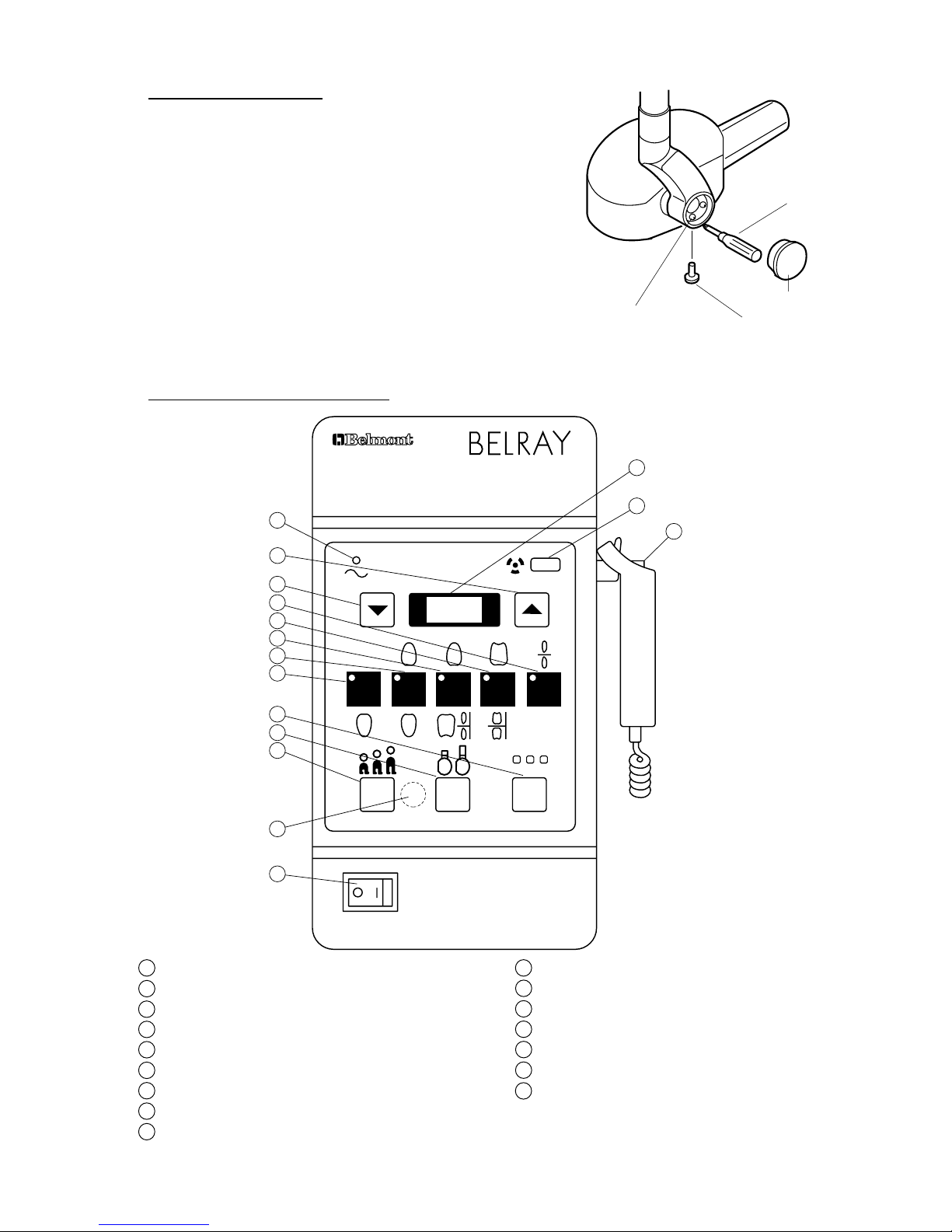
SECTION FIVE : CONTROL IDENTIFICATION AND OPERATION
[1] CONTROL IDENTIFICATION
1
Main Power switch
10
Patient Size Selection Switch
2
Ready Lamp
11
Cone Type Selection Switch
3
Exposure Time Adjusting Sw.(Up)
12
Film Speed Selection Switch
4
Exposure Time Adjusting Sw.(Down)
13
Exposure Time Display Window
5
Tooth Selection Switch (T1)
14
Exposure Warning Light
6
Tooth Selection Switch (T2)
15
Exposure Switch
7
Tooth Selection Switch (T3)
16
Technical Switch
8
Tooth Selection Switch (T4)
9
Tooth Selection Switch (T5)
W A R N I N G
THIS X-RAY UNIT MAY BE DANGEROUS
TO PATIENT AND OPERATOR UNLESS SAFE EXPOSURE FACTORS
AND OPERATING INSTRUCTIONS ARE OBSERVED.
MODEL 096 70kVp 10mA
P C F
T1 T2 T3 T4 T5
abc
15
14
2
3
4
9
8
7
6
12
11
10
16
5
1
13
[3] HEAD POSITIONING
A. Place head into position.
B. If head drifts from the set position, adjust the brake screws
according to the following procedures.
1. Remove the yoke outside cover by loosening cover
screw.
2. Adjust 6 brake screws using phillips screw driver.
3. After adjustment, reattach the yoke outside cover with
the cover screw.
FIGURE 28
Phillips Screw Driver
Yoke Outside Cover
Cover Screw
Brake Screw
Table of contents


