Belson BSA-1520MP3 User manual
MODEL : BSA-1520MP3
MODEL BSA - 1520
IMPORTANT SERVICE SAFETY INFORMATION
1.SAFETY PRECAUTIONS
2. PRODUCT SAFETY NOTICE
some electrical andmechanical parts havespecial safety related
characteristics which areoften not evidentfrom visual inspection.
Nor can the protection they give necessarily be obtained by replacing
them with componentsrated for highervoltage , wattage,etc. Parts
that have special safety characteristics areidentified by a on
schematic and parts list. Use of a substitute replacement that dose not
have the same safety characteristics as the recommended replacement
part might createshock, fire, and/orother hazards. Productsafety is
under review continuouslyand new instructions are issued whenever
Appropriate.
3. Servicing precautions
caution: before servicing the unit covered by this service by this service
manual and its supplements. Read and follow the SAFETY PRECAUTIONS on
this page. NOTE: if unforeseen circumstances create a conflict between
the following servicingprecautions and anyof the safety precautions,
always follow thesafety precautions. Remember:safety first.
General servicing precautions.
A. Always unplugthe unit's AC powercord from theAC power source
(1) removing or reinstalling any component, circuit board, module or
any other unitassembly.
(2) disconnecting orreconnecting any unitelectrical plug or other
Electrical connection.
(3) connecting a test substitute in parallel with an electrical capacitor
caution: a wrongpart substitution or incorrect polarity installation
Of electrolytic capacitorsmay result in an explosion hazard.
B. Do notdefeat any plug/socketb+ voltage interlockswith which
the unit coveredby this service manual might be equipped.
C. Do not apply AC power to this unit and/or any its electrical assemblies
unless all solid-statedevice heat sinksare correctly installed.
D. Always connecta test unitinstrument's ground leadto the unit's
chassis ground before connecting the test instrument's positive lead
always remove thetest instrument's ground leadlast.
4. Laser precautions
Warning!!
1. When servicing.(In case itis necessary toconfirm laser beam
emission ) besure not toplace your eyes any closer than 1 or
30cm from thesurface of the objectivelens on theOptical
Pickup block.
HANDLING THE LASERPICKUP
2. Laser DiodesAre Extremely SusceptibleTo damage from static
electricity even ifa static dischargedies not ruin the diode, it can
shorten its lifeor cause itto work improperly.When replacing the
the pickup, usea conductive maton the floorand desk andwear
a wrist bandconnected to groundthrough a 1M ohm resistorto
protect the laserdiode from staticdamage. If thelens should get
dusty, blow off thedust carefully fromthe object.
3. There are no adjustable parts in the pickup assembly. If it is defective,
replace the wholepickup assembly.
CAUTION:
USE OF CONTROLS, ADJUSTMENTS OR PERFORMANCE OF PROCEDURES
HEREIN MAY RESULTIN HAZARDOUS RADIATION EXPOSURE.
DANGER:
IF INTERLOCK FAILS OR ISDEFEATED, THE LASER LIGHT IS ABLE TO
FUNCTION. THE LASERIS INVISIBLE, AVOID DIRECT EXPOSURE TO BEAM.
Before:
Before returning a unit to the customer, always make a safety check of the
Entire unit, including,but not limited to the followingitems:
a. Be sure that no built-in protective devices are defective and/or have been
defeated during servicing.
(1) protective shields are provided to protect both the technician and the
customer. Correctly replace all missing protective shields including any
removed for servicingconvenience.
(2) when reinstalling the chassis and/or other assemblies in the cabinet, be
sure to put back in place all protective devices, including , but not limited
to , nonmetalliccontrol knobs, insulating fishpapers,
adjustment and compartment covers/shields and isolating resistor/
capacitor networks. Do not operate this or permit it to beoperated
Without all protective devices correctly installed and functioning .
b . Be sure that there are no cabinet openings through which an adult or child
might be able to insert their fingers and contact a hazardous voltage. Such
openings include, butare not limited to, excessively widecabinet ventilation
slots, and an improperly fitted and/or incorrectly secured cabinet
back cover.
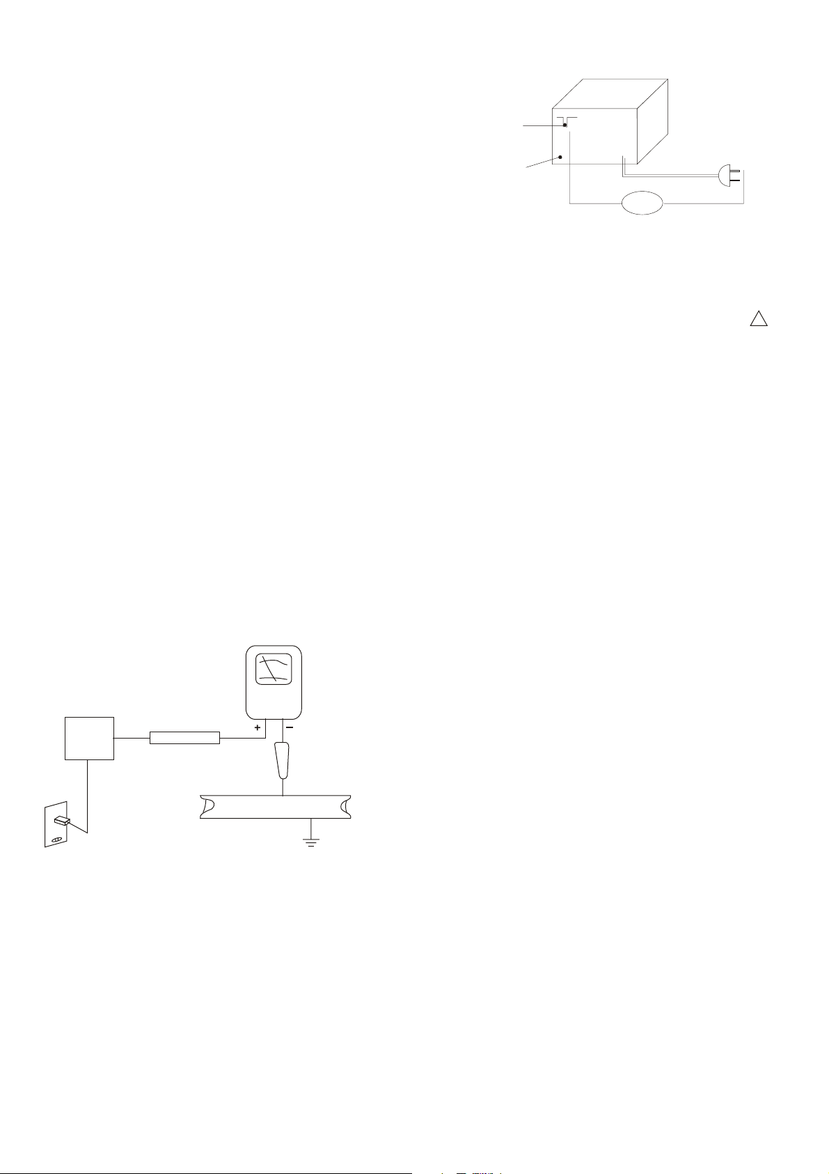
Leakage current hot check - with the unit completely reassembled ,plug the AC
line cord directly into a 120V AC outlet. (Do not use an isolation transformer
During this test.) Use a leakage current tester or a metering system that complies
with American Nationalstandards Institute (ANSI) C101.1"Leakage Current for
Appliances "and Underwriters Laboratories(UL) 1410 (50.7). WITH THE UNITAC
switch first in the ON position And then in the OFF position, measure from a known
earth ground (metal water pipe, conduit, etc.) To all exposed metal parts of the
Unit (antennas, handle bracket, metal cabinet, screw heads , metallic overlays,
control shaft, etc.) Especially any exposed metal parts that offer an
electrical return path to the chassis. Any current measured must not exceed 0.5
milliamp, reverse the unit power cord plug in the outlet and repeat test . ANY
MEASUREMENTS NOT WITHIN THE LIMITS SPECIFIED HERENIN INDICATE A POTENTIAL
SHOCK HAZARD TAHT MUST BE ELIMINATED RETURNING THE UNIT TO THE CUSTOMER.
D. Insulation resistancetest cold check
unplug the power supply cord and connect a jumper wire between the two prongs
of the plug.
Turn on thepower switch ofthe unit.
Measure the resistance with an ohmmeter between jumpered AC PLUG AND EACH
Exposed metallic cabinet part on the unit, such as screw heads, antenna, control
shafts, handle brackets, etc. When the exposed metallic part has a return path to
the chassis , the reading should be between 1 and 5.2 megohms. When there is
no return path to the chassis, the reading must be "infinite". If it is not within the
limits specified, thereis the possibilityof a shock hazard, and theunit must be
repaired and recheckedbefore it isreturned to the customer.
TEST ALL
EXPOSED METAL
SURFACES
(READING SHOULD
NOT BE ABOVE
0.5mA)
LEAKAGE
CURRENT
TESTER
EARTH
GROUND
DEVICE
UNDER
TEST
2-WIRE CORD
ALSO TEST WITH
PLUG REVERSED
(USING AC ADAPTER
PLUG AS REQUIRED)
ANTENNA
TERMINAL
OHMMETER
OM
EXPOSED
METAL
PAR T
!
AC LEAKAGE TEST
2

BSA-1520
ADJUSTMENT LOCATION
3

MODEL:BSA-1520MP3
FM AND AM RF ALIGNMENT CHART ( IF ) ˗˴˸ˍ 28-Jul-04
Step item Input Circuit Output Circuit Tuner Adj - Adjustment
Setup Setup setting Point
Unless otherwise specified set switches as follows:
FM Function: FM
Adjust generator frequency to a center of the FM band where no FM broadcast exists
IF Connect FM IF Connect Co19 and GND FM in band Adjust for straight and
˄Adjustment sweep output IF-OUT terminal to end T304 symmetrical S-curve
terminal to IC302 IF sweep input terminal with max.amplitude.
˅FM Headphone jack or 87.5 MHz L303 Adjust L301 for max output
Band setup speaker terminal 108MHz Done
FM SG ANT. Headphone jack or 90.1 MHZ L302 Adjust for max.output and
ˆTracking (1) Terminal 90.1 MHz, speaker terminal MONO best waveform
1kHz, +-22.5kHz dev
ˇTracking (2) 106.1 MHz, 1 kHz Headphone jack or 106.1 MHz CT303 Same as above.
+-22.5 MHz dev speaker terminal
ˈRepeat steps 3 and 4.
MW
IF Connect standard loop Connect input terminal MW in band Adjust tor max. amplitude
˄Adjustment antenna to output ter- genescope to detector end ˧ˆ˃˅ with symmetrical 450 kHz.
minal of genescope output
˅MW Headphone jack or 522 kHz T301 Adjust L135 for max output
Band speaker terminal 1620 kHz CT302 Adjust CT133 for max output
ˆTracking (1) 612 kHz 400 kHz, Headphone jack or 612 kHz T303 Adjust for max.output and
3% mod speaker terminal best waveform
ˇTracking (2) 1404 kHz 400 kHz, Headphone jack or 1404 kHz CT301 Same as above.
3% mod speaker terminal
ˈRepeat steps 3 and 4.
TAPE SECTION
HEAD ADJUSTMENT (AZIMUTH)
10 kHz test tape (example:MTT-114N) must be used for this adjustment. Connect to VTVM or oscilloscope to the head-
phone JCK or speaker terminal Press the play button.
Adjust the azimuth by using a screw driver to maintain the maximum L & R output voltage. Adjust tape. Please secure the
azimuth position by using locking paint.
RECODING BIAS OSCILLATOR FREQUENCY ADJUSTMENT
Connect the frequency counter to of R601 two ends.
Press REC button of tape .
Adjust T201 obtain 60 kHz +-100 HZ
BSA-1520
ALIGNMENT PROCEDURE
4
Table of contents
Other Belson Stereo System manuals


