Belt-Way Scales 45 User manual


Page 2 of 40
Conveyor Belt Scale
Product Manual
Safety and Warnings
All Belt-Way components MUST be used as described in this manual!
Please note the labels on the integrator and in the manual denote
dangerous voltage. Failure to take safety precautions may result in
serious injury or death.
The protective conductor terminal (Earth Ground) is signified by the
following label. It must be properly connected to earth ground per
local electrical codes.

Page 3 of 40
Conveyor Belt Scale
Product Manual
Table of Contents
Scale Accessories ...............................................................................5
Integrator Specs & Scale Components .............................................6-8
Mechanical Installation....................................................................9-15
Wiring the Sensors / Integrator Installation...................................................16-21
A. Sensor Board ...................................................................................................................................18
B. Terminal Board with AC Power Supply..............................................................................................19
C. Terminal Board with DC Power Supply..............................................................................................20
D. Integrator Board ..............................................................................................................................21
E. IO Board ..........................................................................................................................................21
Integrator Configuration................................................................ 22-36
A. Integrator Navigation.......................................................................................................................22
B. Setup Wizard ..................................................................................................................................23
C. C. Scale Setup .............................................................................................................................23-24
D. Scale Calibration .........................................................................................................................25-28
Zero Calibration....................................................................................................................................25
Test Weight Calibration ...................................................................................................................26-27
Material Test Calibration ......................................................................................................................28
E. Scale Totals .....................................................................................................................................29
F. Device Setup...............................................................................................................................29-30
Plant Connect.......................................................................................................................................31
G. Administration.................................................................................................................................32
Routine Maintenance .........................................................................33
Diagnostics / Troubleshooting ..................................................... 34-36
Message Icons / Error Messages ...........................................................................................................36
Calibration Logs ........................................................................... 37-38
Product Warranty ..............................................................................39
Page 4 of 40
Conveyor Belt Scale
Product Manual
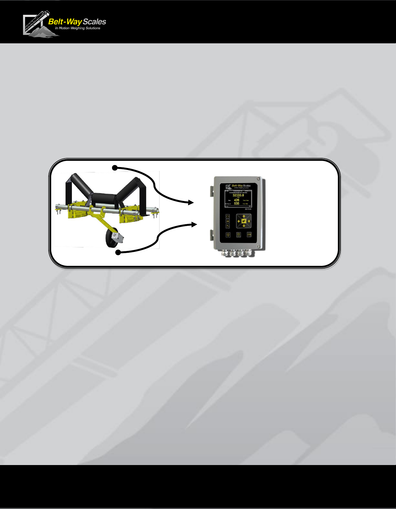
Introduction
The Belt-Way conveyor belt scale is a highly accurate and cost effective in-
motion weighing system. It is designed to measure material flow over a
conveyor belt in real-time. The primary components are the integrator (AKA,
controller, display, indicator), load cell assemblies, and speed sensor. The
scale system processes speed and load signals to accumulate weight and
calculate flow rate.
This manual covers the following belt scale models:
•Model 45 (Low capacity)
•Model 100, Model 200 (Medium capacity)
•Model 350, Model 500, Model 1000 (High Capacity)
This manual pertains to scales operating on firmware 6.43 and above.
A manual for previous versions may be found at beltwayscales.com
BELT
LOAD
BELT
SPEED
ACCUMULATED
WEIGHT
+
FLOW RATE
Page 5 of 40
Conveyor Belt Scale
Product Manual
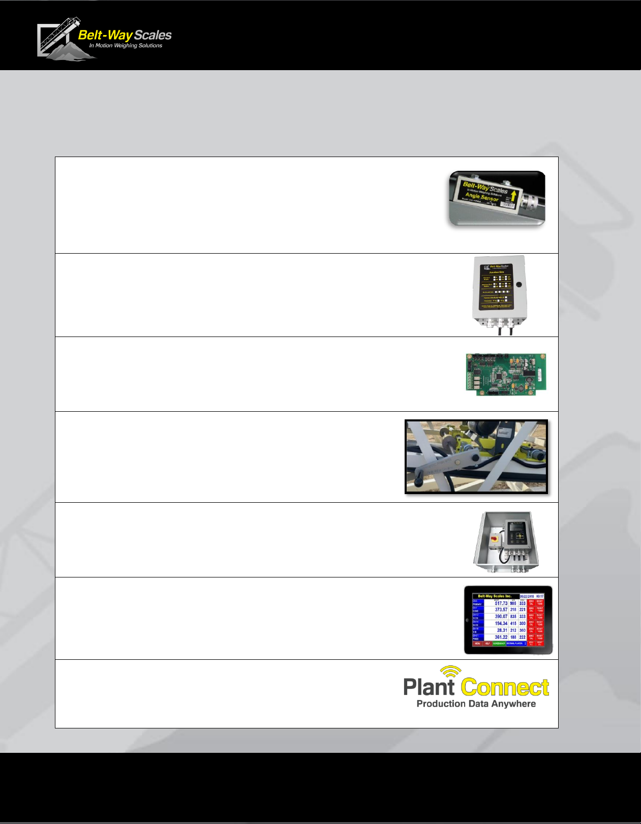
Scale Accessories
Call or visit beltwayscales.com for a complete list of all the accessories
that Belt-Way has to offer.
▪Angle Sensor
The angle sensor eliminates the need for constant recalibration
when the scale is installed on a variable angle conveyor or portable
machine.
▪RS485 Junction Box
A Smart junction box can be installed on the conveyor to place
the scale integrator up to 1000 ft. from the scale.
▪IO Board
The IO board allows the scale to interface with a PLC system, automate
loadout of trucks or rail cars, control a VFD, and blend multiple products.
▪Self-Storing Test Weight Kit
The test weight kit remains installed on the conveyor.
It is activated from one side for easy, safe calibration.
▪Outdoor Protection Enclosure
Heavy duty enclosure offers extra protection for the scale integrator.
Includes power switch.
▪Wireless Multi-Scale Remote Display
The remote display allows multiple scales to be viewed from one
location. Monitor production, clear weight, and perform zero calibrations.
Wireless communication makes installation simple and cost effective.
▪Plant Connect - Online Scale Production Reporting
Our Plant-Connect website allows users to monitor belt
scale production on a PC, tablet or smart phone.
Page 6 of 40
Conveyor Belt Scale
Product Manual
Integrator Specifications
Replacement Part Number: BWINT
100-240 AC Power Supply Factory Installed Part Number: BWPS-AC
100-240 AC Power Supply Field Installation Kit Part Number: BWPSKIT-AC
9-30 DC Power Supply Factory Installed Part Number: BWPS-DC
9-30 DC Power Supply Field Installation Kit Part Number: BWPSKIT-DC
IO Option Board Part Number: BWIO (Factory Installed)
IO Option Board Kit Part Number: BWIOKIT (Field Installed)
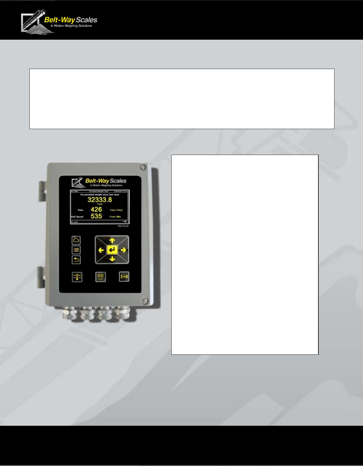
Display: 4.3" Color LCD
Enclosure: Cast Aluminum
Operating Temperature: -20C to 45C
Required Power: 12-24 VDC, 55 Watts
optional 110/240 AC power adapter
Inputs: 8 Load Cells (millivolts)
1 Speed Sensor (0-5 VDC Pulse)
1 Angle Sensor (0- 4 VDC)
Outputs: 1 RS232 (Printer Port)
1 RS232 (Display Port)
1 Ethernet Port (Modbus TCP)
1 USB 2.0 Client
Optional IO Outputs:
4-20 mA outputs (Tons Per Hour)
Digital Pulsed Output (Total Weight)
Min / Max Speed
Min / Max Tons Per Hour
Zero Calibration
Loadout
Optional IO Inputs:
Clear Weight
Print Ticket
Zero Calibration
Page 7 of 40
Conveyor Belt Scale
Product Manual
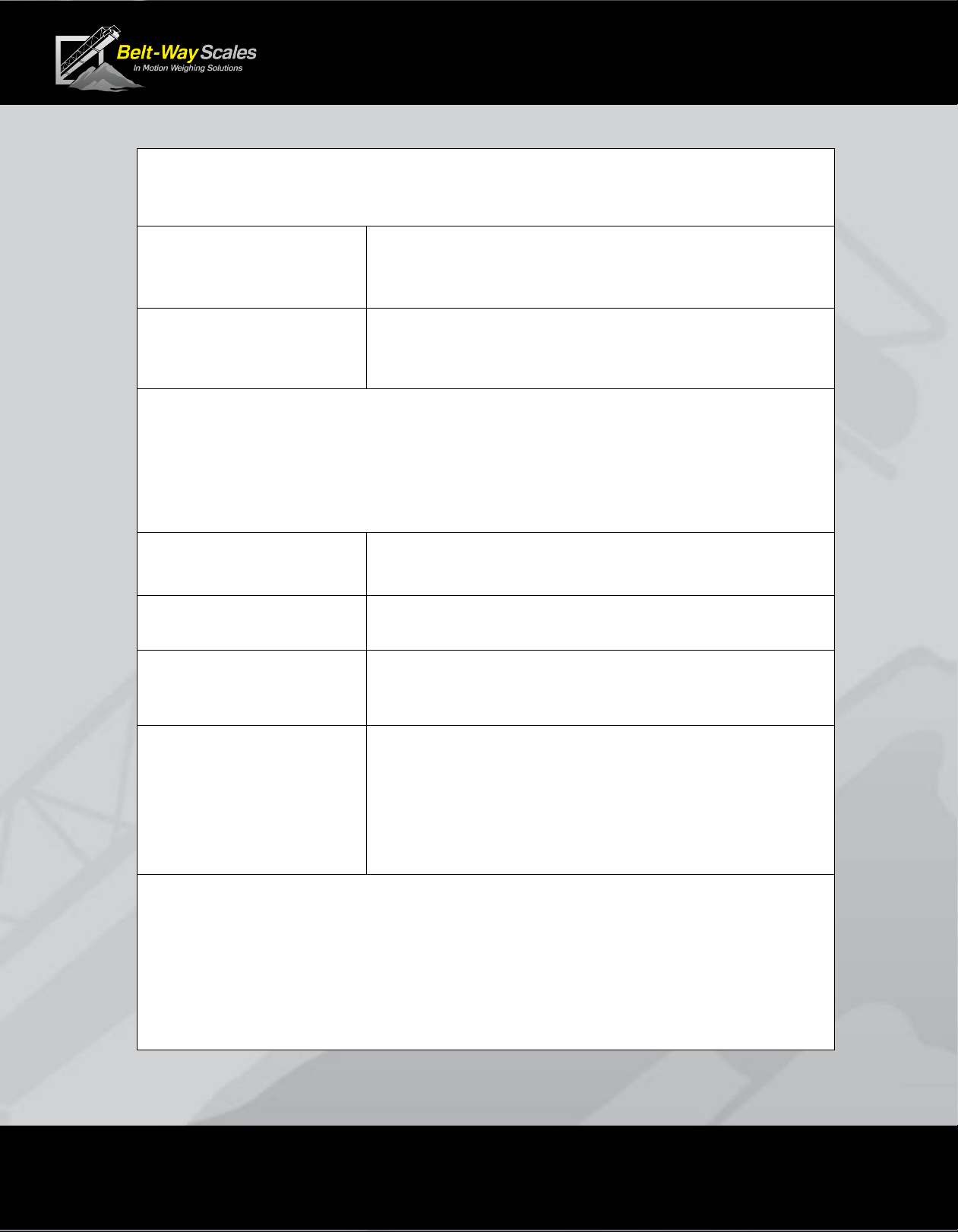
Electrical Ratings
Input Power to
Belt-Way Integrator:
12-30 VDC, 24 VDC 2.25A Max
AC Power option:
Input:100-240VAC 50/60Hz, 1A Max
Output: 24VDC, 2.25A Max
Use of the factory supplied AC Power option is recommended.
AC control power over-current protection with isolated circuit, and
disconnect point such as a breaker or switch box, is recommended.
Conformance to local electrical codes is required.
Digital Inputs:
(IO option installed)
12-24VDC, 50mA sink
Digital Outputs:
(IO option installed)
12 - 24VDC, 100mA sink
Analog Outputs:
(IO option installed)
4-20mA, 24VDC powered loop
Relay Outputs, UL
contact ratings:
(IO option installed)
220VDC, 0.24A, 60W
125VDC, 0.24A, 30W
250VAC, 0.25A, 62.5VA
125VAC, 0.5A, 62.5VA
30VDC, 2A, 60W
Environmental
▪Temperature: Normal operating range -20⁰C to +45⁰C.
▪Humidity: The unit is suitable for outdoor use.
▪Altitude: The unit is suitable for use to elevation of 2000m.

Page 8 of 40
Conveyor Belt Scale
Product Manual
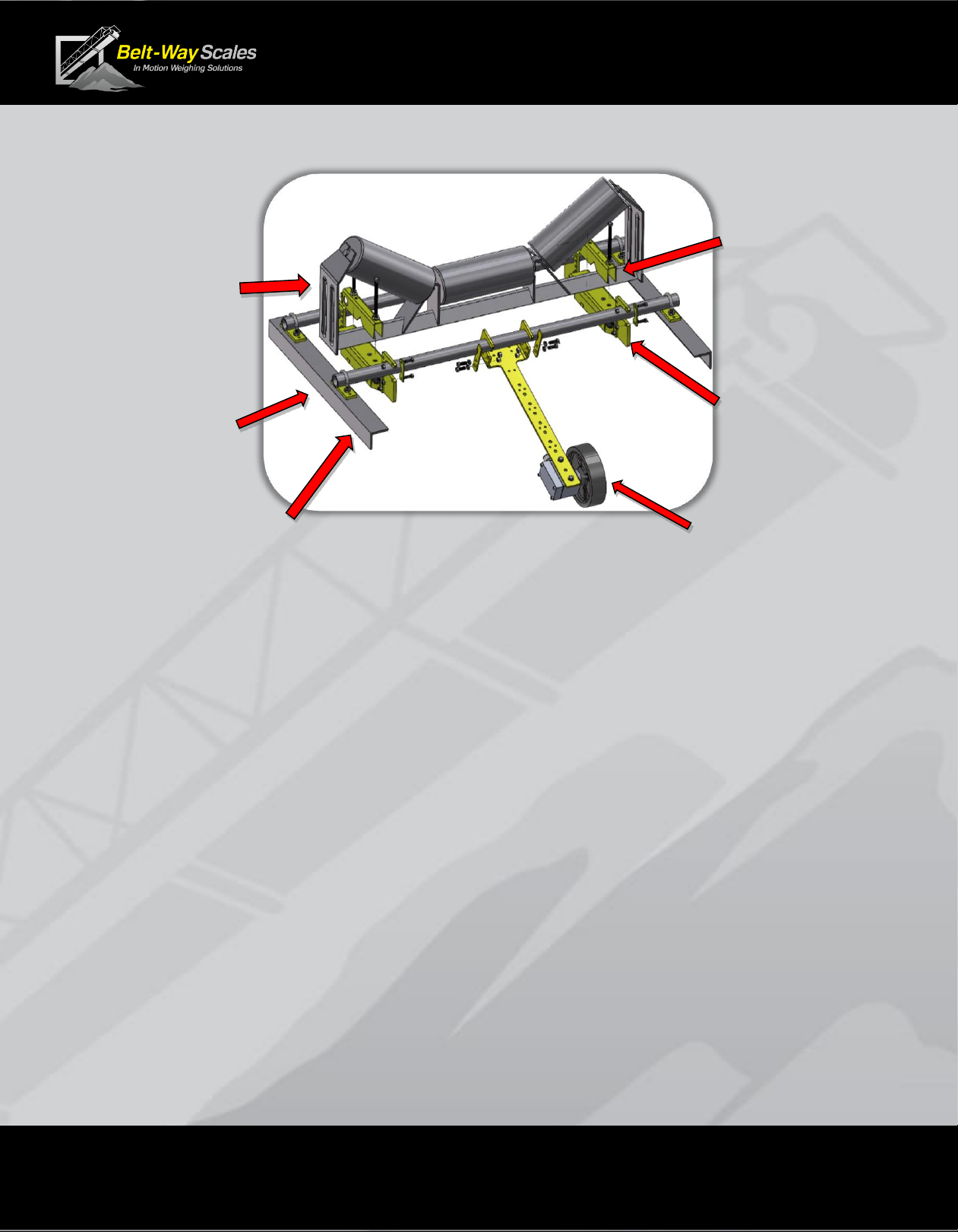
Scale Components
The single idler scale consists of the following components
1 - Integrator
2 - Load Cell
Assemblies
2 - Mounting pipes
1- Hardware Kit
1 - Speed Sensor with
mounting arm
The dual idler scale consists of the following components
1 - Integrator
4 - Load Cell
Assemblies
4 - Mounting pipes
2 –Hardware Kits
1 - Speed Sensor with
mounting arm
Unpacking the Scale
Each scale is comprised of at least three boxes
26” x 10” x 8” - Integrator and Speed Sensor
26” x 10” x 8” - Load Cells and Hardware kit
48”, 60” or 72” long boxes for mounting pipe
and various sizes for angle sensors and other accessories
Page 9 of 40
Conveyor Belt Scale
Product Manual
Mechanical Installation
2D component and installation drawings are available at beltwayscales.com
3D drawings are available by request.
A. Recommended Tools
▪Cutting torch and grinder (remove idler mounting feet)
▪Heavy duty drill or magnetic drill press (drill u-bolt holes)
▪Tape Measure (measure idler distance)
▪Angle finder or phone app (measure conveyor angle)
▪1/2”socket and wrench (load cell and speed sensor brackets)
▪9/16” deep socket and wrench (V-block, u-bolts, leveling bolts)
▪String (to level weighbridge idlers)
▪Shim kit (to adjust idler height)
▪4 way screwdriver (integrator mounting, integrator door, hose clamps)
▪Small Belt-way screwdriver (integrator wiring)
B. Conveyor Design Recommendations
The following design suggestions are essential for best scale accuracy and repeatability.
▪Reduce speed whenever possible to maximize belt load. Slow moving, heavily loaded belts
work better than fast moving, lightly loaded belts.
▪Proper belt tension must result in 1%-2% deflection between idlers.
For example, 2% deflection is 1 inch sag in the belt over a 4 ft. idler spacing.
▪Lower trough angles, 0-35, are preferred. Avoid 45troughed idlers.
▪Install a belt scraper to keep the belt clean.
▪Cover the conveyor to shelter it from wind, rain and snow.
MOUNTING PIPE
AND
LEVELING
PLATES
MODIFIED
CEMA IDLER
LOAD CELL
ASSEMBLIES
SPEED
SENSOR
V-Block
CONVEYOR
FRAME
Page 10 of 40
Conveyor Belt Scale
Product Manual
C. Scale Placement
▪Install the scale where it is easily accessible for maintenance purposes.
▪Choose a very rigid section of conveyor such as an idler over a brace.
▪The scale must be at least 40 ft. away from curves in the conveyor.
▪Stay at least three idlers away from the head pulley, tail pulley, and loading points.
Material must not impact the belt near the scale!
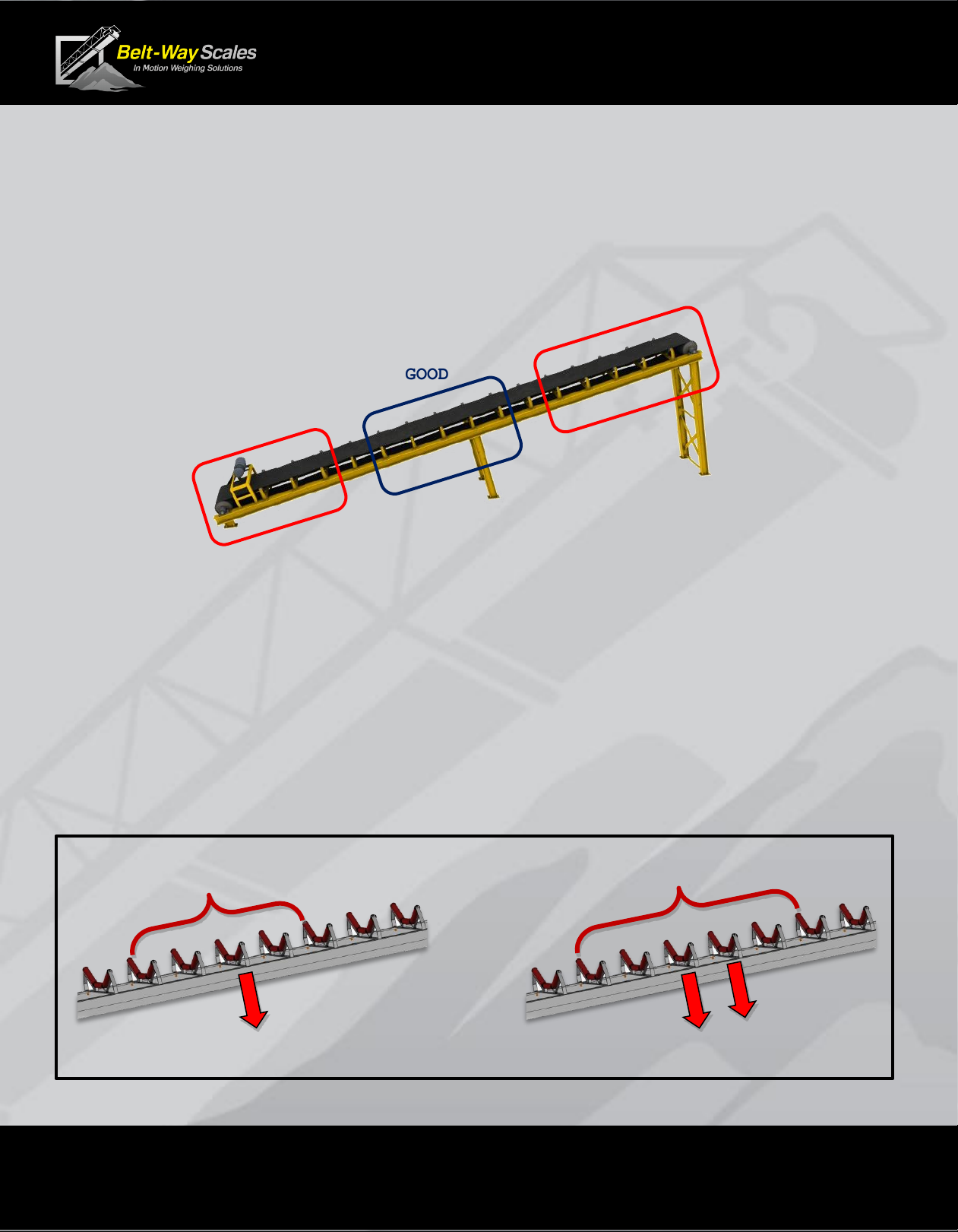
D. Define the Weighbridge
The Weighbridge is the section of belt actively being weighed by the scale.
▪The weighbridge idlers must be in good mechanical condition.
▪The weighbridge idlers must be the same trough angle, and diameter.
▪The weighbridge idlers should be an equal distance apart.
▪Skirting should not make contact with the belt in the weighing area.
▪A single idler weighbridge consists of 5 idlers.
Scale must be installed on the center idler
▪The dual idler weighbridge consists of 6 idlers.
The scale must be installed on the 2 center idlers.
GOOD
AVOID
AVOID
5 Idler Weighbridge
Single Idler Scale
6 Idler Weighbridge
Dual Idler Scale
Page 11 of 40
Conveyor Belt Scale
Product Manual
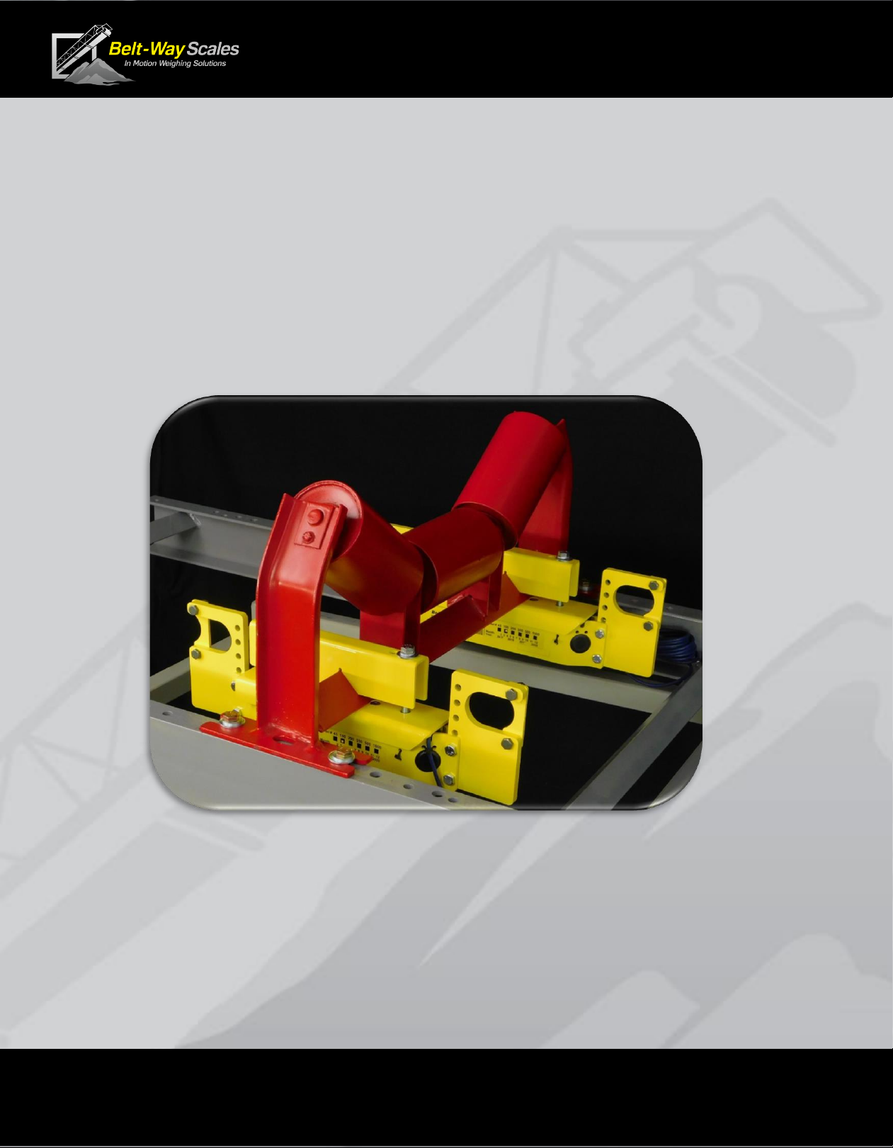
E. Attach Load Cell Assemblies to idler
▪Bolt the load cell assemblies to the idler as shown using the V-Block.
▪The load cell cable should point downhill.
▪Leave plenty of clearance between the load cell assembly and conveyor frame.
▪Do not overtighten the V-Block bolts.
▪The bolts should be tightened ¼ turn after compressing the lock washer.
▪Position the load cell assemblies an equal distance from the conveyor frame.
▪This balances the load of the belt evenly between the load cells.
NOTE: Stainless Steel Load Cells –Do not use a full thread bolt,
or over tighten the existing V-Block bolt on a stainless steel load cell.
This will damage the load cell cable.

Page 12 of 40
Conveyor Belt Scale
Product Manual
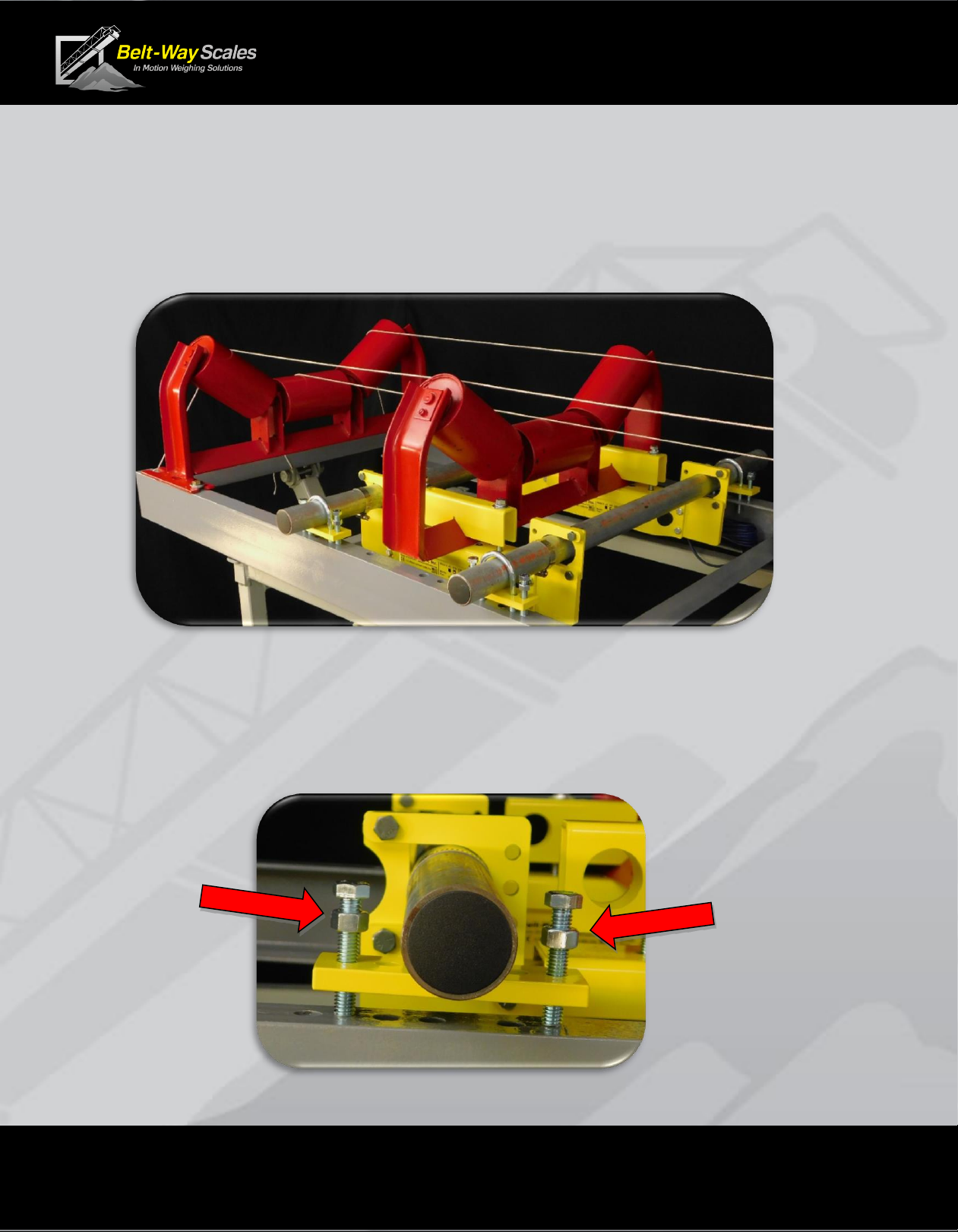
F. Install Scale Support Pipes
This step is extremely important to ensure long term scale accuracy.
▪The mounting pipe must touch the strap on the uphill side of load cell assembly.
▪The strap on the downhill side must create an oval opening.
▪Center the pipe in the oval hole.
▪The load cell assembly must be free to move up and down slightly on the pipes.
This eliminates torque on the conveyor frame, which allows automatic alignment
of the weighing elements.
▪Install the four hose clamps onto the pipe with the screw fitting directly over the
top of the pipe, but do not tighten the clamps at this time.
Uphill side:
Retaining strap
fits tightly around the pipe.
Downhill side:
Retaining strap
forms oval hole around the pipe.

Page 13 of 40
Conveyor Belt Scale
Product Manual
G. Drill U-bolt Holes
▪Use the leveling plate as a drill template for the U-bolts.
▪The leveling plates and pipe centers should measure 15”apart.
▪The holes should be at least 7/16” to clear the 3/8” -16 U-bolts.
H. Remove and Modify Idler
▪Unbolt idler from frame.
▪Remove the idler mounting feet to create clearance above the conveyor frame.
▪If the idler feet are not removed, all other weighbridge idlers must be shimmed up 3/8”.
▪Make sure the idler is centered from left to right on the conveyor.
15 inches
15 inches
Page 14 of 40
Conveyor Belt Scale
Product Manual
I. String-Line Idlers to level the Weighbridge:
This is an extremely important step in the installation process.
▪The empty belt must rest uniformly on all idlers within the weighbridge.
▪Use a minimum of three strings to align all 5 or 6 weighbridge idlers.
▪Shim idlers if necessary to bring them into alignment.
▪Use the 3/8-16 leveling bolts to adjust the scale idler height.
▪Tighten U-bolts evenly so pipes remain parallel and oval clearance
around bottom pipe is maintained.
▪Tighten the jam nuts against the leveling plate to lock the pipes in place.
Page 15 of 40
Conveyor Belt Scale
Product Manual
J. Install Hose Clamps:
▪Install the hose clamps on the outside of the load cell
assembly.
▪Leave clearance so the clamps don’t bind between the
pipe and load cell bracket.
▪Rotate the screw barrels away from the gaps between
the hanger brackets and the pipes.
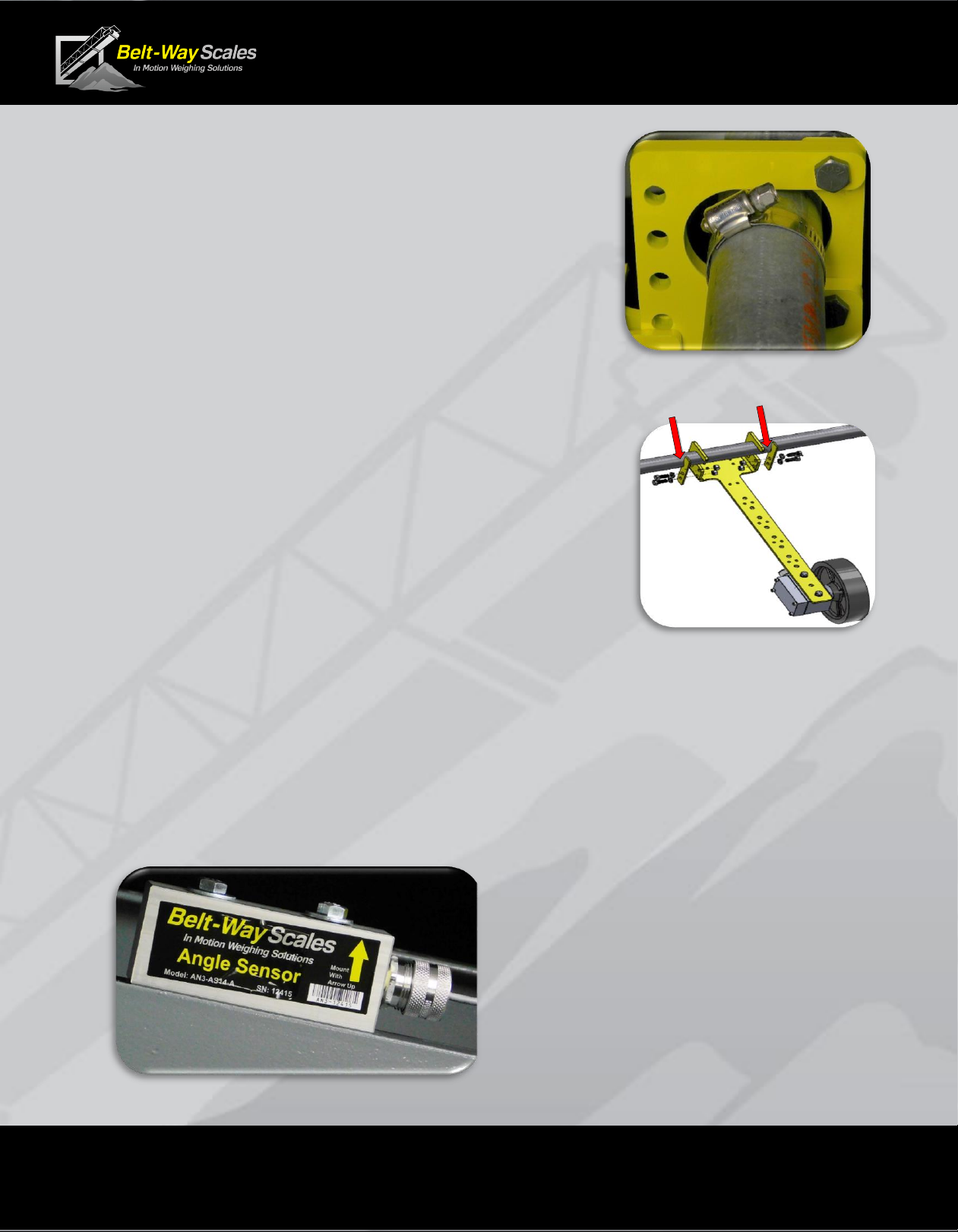
K. Install Speed Sensor Assembly
▪The standard speed sensor assembly may hang
from either pipe. It must point downhill.
▪The wheel must ride smoothly on the belt.
▪Avoid installing it near return idlers that may cause the
wheel to bounce.
▪A small amount of weight may be added to the speed
wheel arm to hold the wheel firmly on the belt.
▪Use two hose clamps to retain the mounting arm .
▪Secure the cable to the arm with cable ties. Route the
cables carefully along the conveyor frame so they are
protected from falling debris and pinch points.
L. Optional Angle Sensor
Any conveyor that frequently changes angle must have an angle sensor installed.
▪Mount the Angle Sensor directly on the conveyor frame.
▪Mount in the direction of the head pulley.
▪Reference the UP arrow indicator on the sensor.
Caution: Excessive vibration
will interfere with Angle Sensor
performance.
Hose Clamps

Page 16 of 40
Conveyor Belt Scale
Product Manual
Wiring the Sensors
A. Extending the sensor cables
▪Standard load cells, speed sensors, and angle sensors have 30 ft cables.
▪50 ft. cables are available upon request for an additional charge.
▪Factory supplied cables may be extended up to 100 ft. in one of four ways:
1.Solder and waterproof a similar shielded cable onto the original.
2.Use a waterproof terminal strip. Do NOT sum multiple load cells into a single
cable. Each load cell must individually connect to the integrator.
3.Belt-Way RS485 Junction box.
4.Belt-Way RS485 Junction box with Quick Disconnect option
▪Distances greater than 100 ft should utilize the Belt-Way RS485 Junction box.
▪Use of any style crimp connector or wire nuts to extend sensor cables is
unacceptable and will void the warranty!
▪Use of unshielded cable is unacceptable and will void the warranty!
B. Connecting the sensors to the integrator or junction box.
C. Connecting the shield wire
Use a small screwdriver to gently pry the connector
out of the terminal strip.
Insert the connector at an angle to snap
It back into place
All sensor wires MUST be connected as shown below.
Properly terminating the shield wire is required to prevent electrical interference.
Route the cable through the rubber grommet
and loop the shield wire back out so it touches the aluminum connector.

Page 17 of 40
Conveyor Belt Scale
Product Manual
Always disconnect power before servicing the integrator.
Make sure you LOCK OUT, TAG OUT and TRY OUT the electrical system before any maintenance
or service. Please follow all Federal, State and Company Safety procedures and policies when
working with this product.
Integrator Installation
The mounting kit includes four mounting feet and four M6 x 1mm x 60mm screws with nuts to attach
mounting feet to the integrator. Customer must supply fasteners from mounting feet to mounting
location. Leave a minimum of 3”clearance on the hinge side to allow the door to open.
The integrator is weatherproof, but should be installed in a
protective enclosure whenever possible.
Physical damage to the integrator is not covered under warranty.
WARNING!
Do not install the integrator where it is subject to vibration.
Damage from vibration is not covered under warranty
Rubber or neoprene should be used to dampen the
effects of vibration. This is especially important on
portable machines. Vibration Mounting Kits are
available from Belt-Way.
Order part number BWVIBRATIONMT.
Integrator
Rubber Mount

Page 18 of 40
Conveyor Belt Scale
Product Manual
A.Sensor Board
The load cells, the speed sensor, and the angle sensor
all connect to the sensor board unless a junction box is required.
.80 A Fuse
Speed Sensor Wiring
SIGA –GREEN
+5V –RED
GND –BLACK & WHITE
Angle Sensor Wiring
SIG –GREEN
GND - WHITE
+5V –RED
GND - BLACK
Load Cell Wiring
-SUP –BLACK
+SUP –RED
-SIG - WHITE
+SIG –GREEN
A Single Idler Scale must use LC1 and LC2.
A Dual Idler Scale must use LC1 to LC4.
DO NOT SUM THE LOAD CELL WIRES BEFORE
CONNECTING TO THE INTEGRATOR!
The load cells are processed independently and require
individual wires for each load cell connector.
Summing the wires will cause the scale to malfunction.
Page 19 of 40
Conveyor Belt Scale
Product Manual
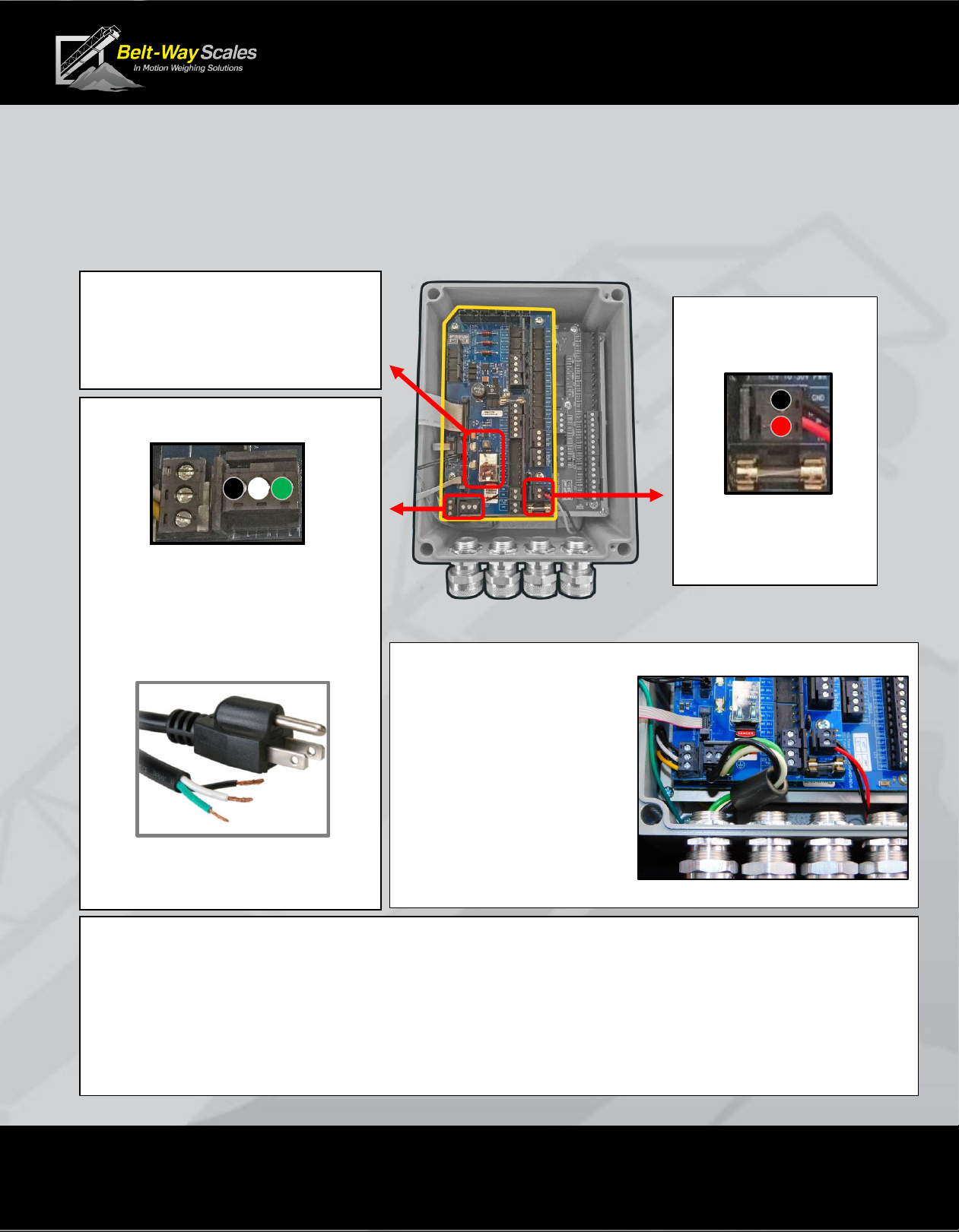
B.Terminal Board with 110 / 240 AC Power Supply
All power wiring must conform to local and national electrical codes.
Always disconnect power before servicing the integrator.
The AC Power supply is installed below the Sensor Board. It converts 110/240 AC to 24 VDC.
Ethernet Port
Power Over Ethernet 1.25 A Fuse
Only install this fuse when using
a wireless transmitter. See page 21
110 AC - To Power Supply
LINE –BLACK
NEUTRAL - WHITE
EARTH GROUND –GREEN
The user must supply a minimum
16-gauge 3 wire power cord.
Connect to a properly grounded
receptacle that is rated for at least
15 Amps at 110 VAC.
24 VDC
From Power Supply
GND = BLACK
+24V = RED
6 A Fuse
NOTE FOR GENERATOR POWER
A generator may produce unstable power during the startup or shutdown sequence.
The integrator is sensitive to power fluctuations and should be disconnected at startup and
shutdown to prevent data loss. Use a breaker or simply unplug the power cord from the
outlet until the generator is fully powered up.
Ferrite Bead Installation
Each scale includes a
Ferrite Bead to meet
CE emission requirements.
Run all AC wires through
it as shown to the right.
Page 20 of 40
Conveyor Belt Scale
Product Manual
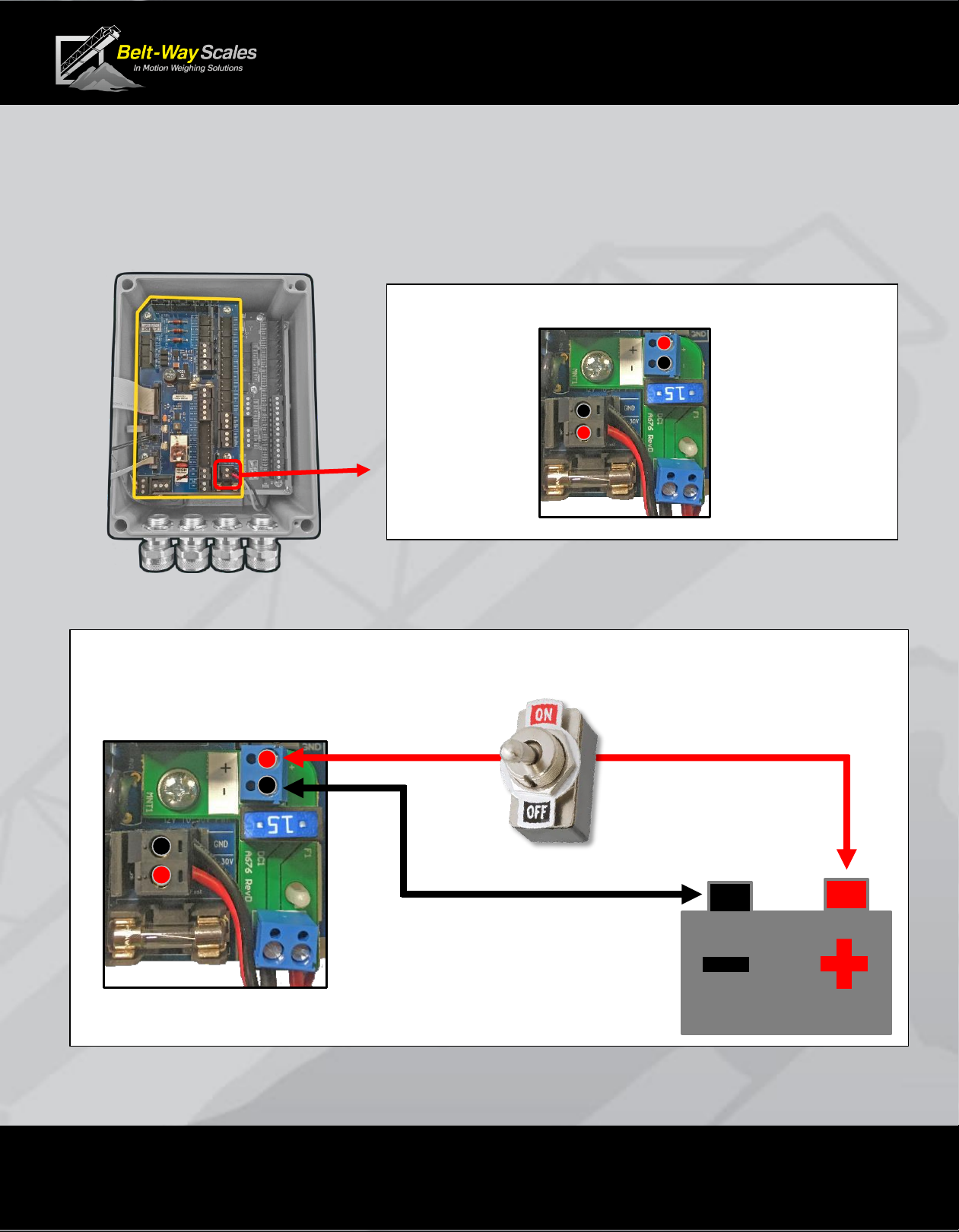
C.Terminal Board with DC Power Supply
The DC Power supply is installed below the Sensor Board.
It boosts 9-24 VDC up to 24 VDC and regulates the voltage during engine cranking.
User should supply a toggle switch to isolate the integrator from the battery.
9-24 VDC Landing Board
+ 9-24 VDC
- VDC
7.5 A Fuse
-VDC = BLACK
+24 VDC = RED Input from Battery
( Output from to Power Supply
Power Supply
To Integrator
This manual suits for next models
5
Table of contents
Other Belt-Way Scales Scale manuals


