bemodern 3062 Operation and maintenance manual
1
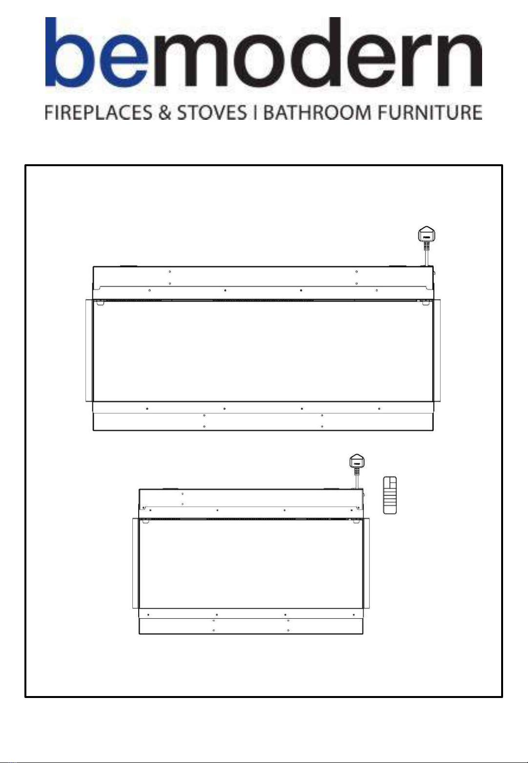
750 Landscape, 1000 Landscape
3 Sided Electric Fires
Instructions for operation
R1 May 21

2
Technical Specification
Model No.: 3062, 3083
Supply Voltage: AC 220-240V 50-60Hz
Maximum power consumption: 2KW
Power for flame effect 750: 20W (LED 15W + Motor for flame 5W)
Power for flame effect 1000: 30W (LED 25W + Motor for flame 5W)
Heat Output:
Nominal heat output (Pnom): 2KW
Minimum heat output (indicative) (Pmin): 1KW
Maximum continuous heat output (Pmax): 2KW
Auxiliary Electricity Consumption:
At nominal heat output (elmax): 0W
At minimum heat output (elmin): 0W
In standby mode (elSB): 0.45 W
Single
stage heat output and no room temperature control No
Two
or more manual stages, no room temperature control No
With
mechanic thermostat room temperature control No
With
electronic room temperature control No
Electronic
room temperature control plus day timer No
Electronic
room temperature control plus week timer Yes
Room
temperature control, with presence detection No
Room
temperature control, with open window detection Yes
With
distance control option No
With
adaptive start control No
With
working time limitation No
With
black bulb sensor No
Type of heat output / room temperature control
Other Control Options
200811_1

Read all the instructions carefully before using the appliance.
For indoor use only. This appliance is not suitable for use outside the house and only suitable for well
insulated spaces or occasional use.
Do not use this appliance in the immediate surroundings of a bath, a shower or a swimming pool.
Do not use this fire as a free-standing appliance. It must always be fixed to the wall, fireplace mantel, floor etc.
This fire must not be located immediately below a socket-outlet.
This appliance must be earthed.
This appliance must not be supplied through an external switching device, such as a timer, or connected to the
circuit that is regularly switched on and off by utility in order to avoid a hazard due to the inadvertent resetting of
the thermal cut out.
A non-rewireable plug fitted with a 13A fuse is supplied. Should the fuse or plug need replacing, and you are
competent to do so, it must be replaced with a 13A fuse or plug being 13A BS1363A approved.
If the power cord is damaged, it must be repaired by the manufacturer, its authorised service centre or professional
person.
The meaning of this symbol is Warning: in order to avoid overheating, do not allow the
appliance to be covered or let the air inlet/outlet become obstructed.
To reduce the risk of fire, keep textiles, curtains, or any other flammable material a minimum distance of 1 meter
from the air outlet.
Keep the power cord away from hot surfaces and hot conditions. Do not route the power lead in front of the
appliance.
Do not use this fire in rooms that have explosive fumes in them (for example petrol), or if you are using solvents,
glue, aerosol spray or in flammable paints, as these may catch fire.
This appliance can be used by children aged from 8 years and above and persons with reduced physical, sensory or
mental capabilities or lack of experience and knowledge if they have been given supervision or instruction
concerning use of the appliance in a safe way and understand the hazards involved.
Children and vulnerable people must be supervised at all times when using this appliance, as some parts can
become very hot and cause burns.
Do not use this appliance in small rooms when they are occupied by persons not capable of leaving the room on
their own, unless constant supervision is provided.
Cleaning and user maintenance shall not be made by children without supervision.
Children aged from 3 years and less than 8 years only can switch on / off the appliance provided that it has been
placed or installed in its intended normal operating position and instructions and supervisions concerning the safe
way of the use of the appliance are offered. Children aged from 3 years and less than 8 years shall not plug in,
regulate and clean the appliance or perform user maintenance.
This appliance shall not be played with by children.
Children of less than 3 years should be kept away unless continuously supervised.
Keep the power plug accessible after installation.
3
200811_1
Important Safety Information
4
Operation Instructions
200811_1
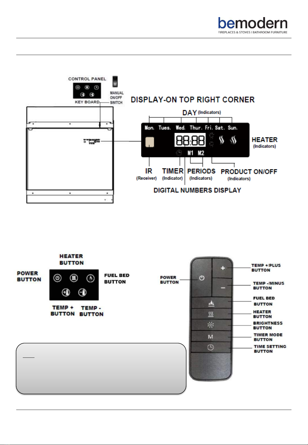
The fire can be operated either manually via the buttons located on the front right side of the unit or by the
supplied remote control. The manual ON / OFF switch located on the right hand side of the manual buttons must
be in the “I” position before trying to operate the fire
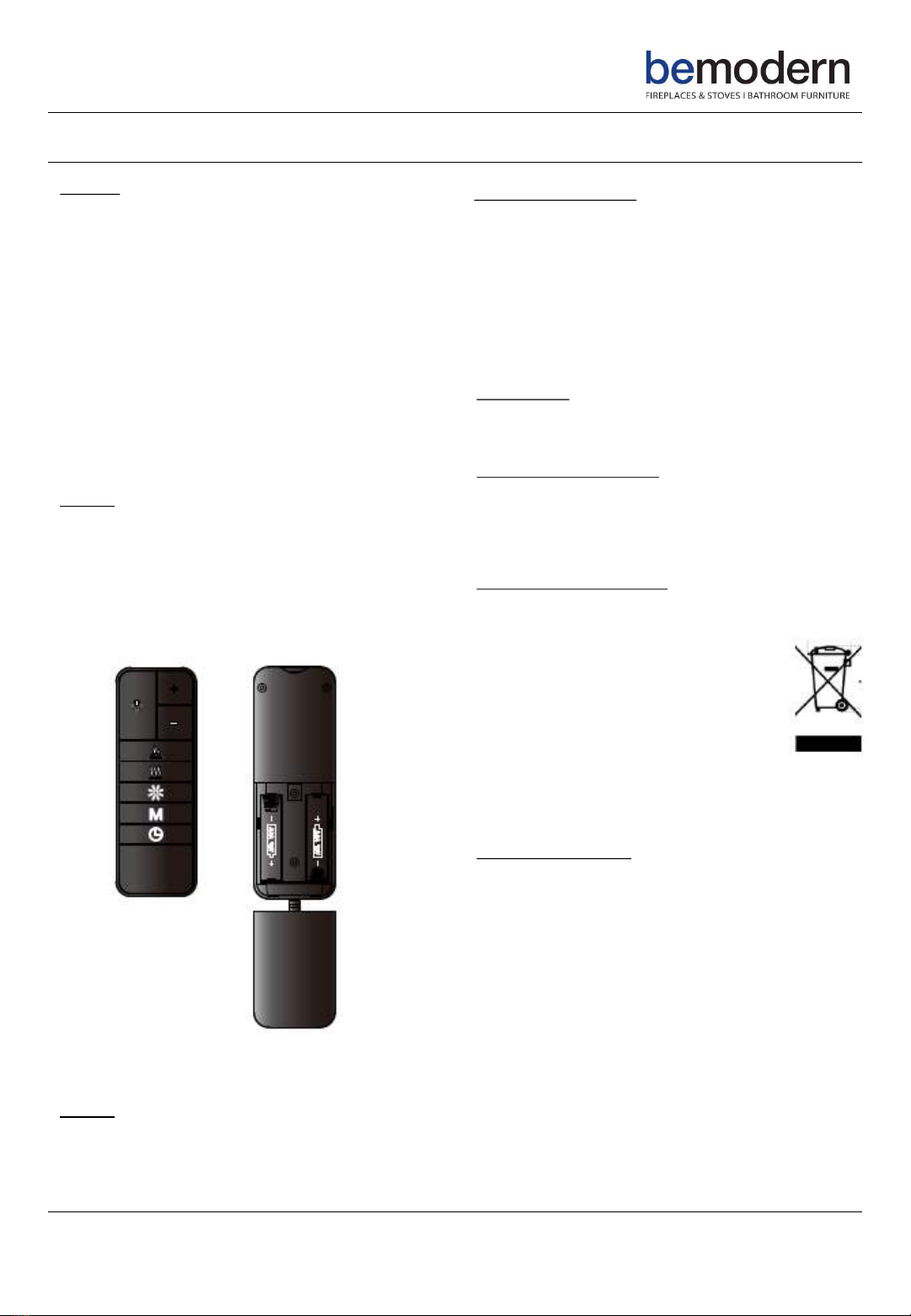
Note: Before attempting any operation with the remote control,
press and slide the battery door on the back of the remote to open
the battery compartment. Insert the 2 x AAA batteries checking
that the + and –sides of the batteries match the inside of the
battery compartment. Replace the battery compartment door.
Manual Operation
When using either manual or remote control
Manual Operation
5200811_1
Operation Instructions continued…
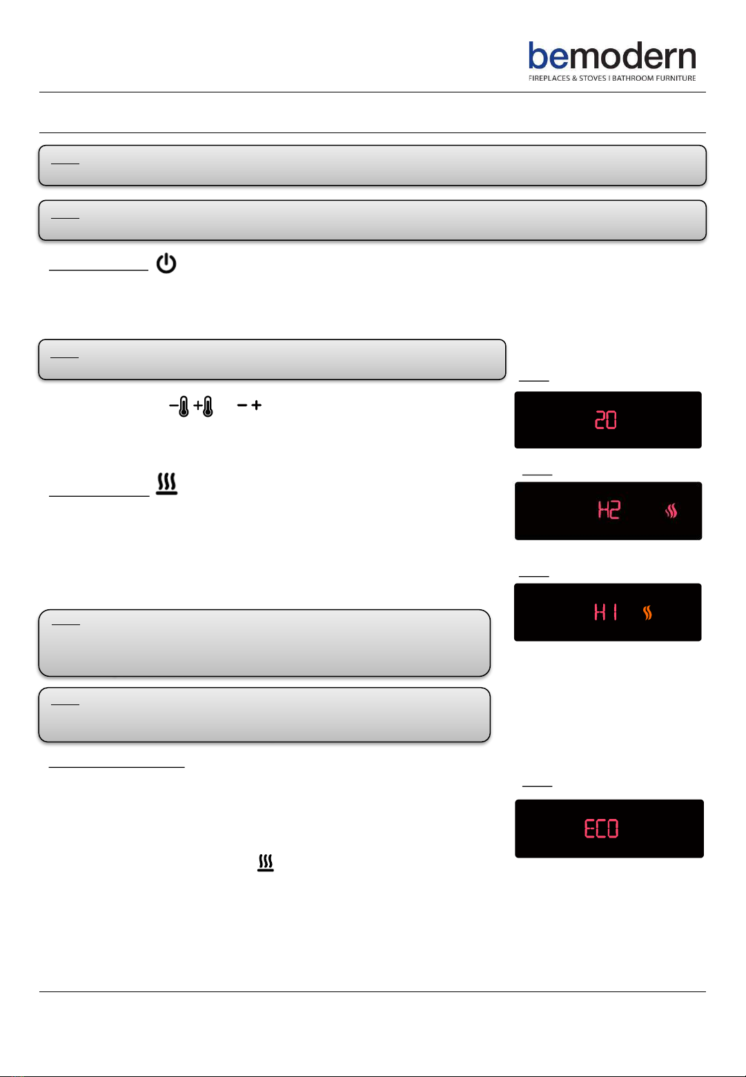
Powering the fire
Press the power button to supply power to all the functions of the fire and put the fire into standby mode, the
current room temperature will be shown on the display.
Press the power button again to turn off all functions
Temperature setting or
Fig 1.
Adjust the temperature to the desired setting (15° to 30° range) using the
Temp + and Temp –buttons. The set temperature must be above the room
temperature for the heating function to operate. Fig 1.
Heater Operation
Press the heater button to select 2000W, H2 and a red flame symbol will be
displayed. See Fig 2.
Press the heater button again to select 1000W, this time H1 and an orange
flame will be displayed. See Fig 3.
Press the heater button again to turn the heater off
Fig 2.
Fig 3.
Open Window Function
This appliance has an “Open Window Detection Function”. When the heater
is in operation H1 or H2 and the ambient temperature drops 5° within 10
minutes ECO will appear in the display and the heat function will
automatically turn off.
This means there is a window open or a cold draft coming into the room past
the fire. Close the window and press on the manual control panel or the
remote control to restart the heater. See Fig 4.
Fig 4.
Note: The unit may emit a slight harmless odour and smoke when first used. This odour and smoke is normal and
is caused by the internal heating parts and will not occur again.
Note: The below functions can be controlled by either the manual buttons on the fire or the remote control.
Ensure the ON / OFF switch is in the “I” position before trying to operate the fire.
Note: All previous settings are held in the memory so the next time you power
up the fire it will turn on with the same settings unless power to the unit is lost
Note: On either heat setting the heat function will turn off when the room
temperature reaches the set temperature. The heater will automatically
restart when the room temperature drops 3° below the set temperature as
detected by the fire unit
Note: The heater fan will run for approximately 30 seconds after the heat
has been turned off, this is to remove any residual heat and protect the
components from potential overheating.

6200811_1
Operation Instructions continued…
Fuel Bed Operation
Press the fuel bed button to select from seven different fuel bed colour options.
Fig 5.
1 –OFF 5 - Blue
2 –Red 6 - Purple
3 –Sky Blue 7 - Green
4 –Orange 8 –Cycle between 2 and 7
Fig 5.
Press and hold button for 2 seconds to turn ON / OFF the downlights.
ON is displayed when the downlights are on.
Fig 6.
Fig 7.
Brightness Operation
The brightness setting of the flame effect can also be adjusted. This is done
by pressing the brightness button and selecting one of the following
options. Fig 8.
H –Maximum Setting
C –Intermediate Setting
L –Minimum Setting
Fig 8.
Note: The last setting “8” is where the unit cycles through all seven colours.
Pressing the stops the cycling and holds the unit on one preferred
colour, a circle will be displayed. See Fig 6.
When one of these modes has been selected, this will become the default
mode when the unit is next turned on.
Note: The brightness setting of the flame effect can only be adjusted by using
the remote control

7200811_1
Operation Instructions continued…
Setting The Day and Time
The following can only be set using the remote control.
Press the power button to turn the unit on.
Press and hold the time setting button for two seconds to display the time
and day (no numbers are shown as time has not been set) See Fig 9.
Press the time setting button and the day setting will start to flash. See Fig 10.
Adjust the day setting using the Temp + Temp –buttons.
Press the time setting button and the hour setting will start to flash, adjust the
hour using the Temp + and Temp- buttons.
Press the time setting button and the minute setting will start to flash, adjust
the minute setting using the Temp + and Temp –buttons
Press the time setting button to set the time and exit the day / time setup.
Fig 9.
Fig 10.
Setting The Weekly Timer
This timer allows for two ON / OFF periods (M1 / M2) for each day of the week.
The timer can be set using the following procedure:
Press the power button to turn the unit on.
Press and hold the timer mode button for two seconds to enter the timer
settings. The settings for the first ON / OFF period (M1) for Monday will be
shown with the first ON time and hour setting flashing. See Fig 11.
Adjust the hour setting using the Temp + and Temp –buttons, press the time
setting button to select the minute, adjust this setting using the Temp + and
Temp –buttons.
Press the time setting button and the display will move to the first OFF time
setting. See Fig 12.
Repeat the above steps to set the first OFF time.
Press the time setting button and the display will move to the second ON / OFF
period (M2), with the second ON time setting displayed. See Fig 13.
Repeat the above steps to set the second ON / OFF period
Press the time setting button and the display will move onto the first ON / OFF
period (M1) for Tuesday with the first ON time setting displayed.
Repeat the above steps for Tuesday’s settings and repeat process for
Wednesday to Sunday settings.
Having confirmed Sunday’s settings exit the timer setting, this can be done by
not using the remote for 10 seconds and the unit will then default into normal
operating mode. To activate the timer settings press the timer mode button
until the timer symbol is displayed on the screen. See Fig 14.
Fig 11.
Fig 12.
Fig 13.
Fig 14.
Note: The time and day must be set before the timer mode can be activated. The unit can still be operated
normally when in timer mode using the heater function
Note: If the power to the unit is lost then the time / day and weekly timer settings will have to be reprogrammed.
8200811_1
General Information
Cleaning
Allow the product to completely cool before
handling or cleaning it.
•Switch off and unplug from the power supply
before cleaning
•Using a soft moist cloth with or without mild soap
solution carefully clean the exterior of the
product
•Do not allow water or other liquids to run into
the interior of the product as this could create a
fire and / or an electrical hazard
•We also recommend the periodic cleaning of this
product by lightly running a vacuum cleaner
nozzle over the grill to remove any dust or dirt
that may have accumulated inside or on the unit.
Caution: Do not use harsh detergents, chemical
cleaners or solvents as they may damage the
surface finish of the plastic components.
Battery Replacement –Remote Control.
•Slide open the battery cover on the back of the
remote control
•Install AAA batteries into the remote control
•Replace the battery cover
Discard leaky batteries.
Dispose of batteries in a correct manner according to local
regulations.
Caution: Any battery may leak electrolyte if mixed with a
different battery type, if inserted incorrectly, if all the
batteries are not replaced at the same time, if disposed of
in a fire or if an attempt is made to charge a battery not
intended to be charged
Thermal Safety Cut-out
A thermal safety cut-out is incorporated in the heater
to prevent damage due to overheating. This can
happen if the heat outlet is restricted in any way. The
heater will switch on once the obstruction has been
removed and the heater has cooled. If the cut-out
continues to operate intermittently the heater should
be switched off and a service agent contacted.
Maintenance
Warning: Always disconnect from the power supply
before attempting any maintenance
Light Emitting Diode (LED)
This fire is fitted with LED (Light Emitting Diode) bulbs
in place of traditional incandescent bulbs. These
generate the same light level as traditional bulbs but
use a fraction of the energy consumed.
Correct Disposal of Product
This marking indicates that the product
should not be disposed with other
household wastes. To prevent possible
harm to the environment or human health
from uncontrolled waste disposal, recycle it
responsibly to promote the sustainable
reuse or material resources. To return your
used device please use the return and
collection systems or contact the retailer
where you purchased the product. They
can take this product for environmental
safe recycling
Warranty Information
The manufacturer provides warranty in accordance
with the legislation of the customers own country of
residence, with a minimum of 1 year starting from the
date on which the appliance is sold to the end user.
The warranty only covers defects in material or
workmanship.
The warranty will not apply in cases of:
•Normal wear and tear
•Incorrect use, e.g. overloading of the appliance, use
of non-approved accessories
•Use of force, damage caused by external influences
•Damage caused by non-observance of the user
manual e.g. connection to an unsuitable mains
supply or non-compliance with the installation
instructions
•Partially or completely dismantled appliances

9
Environment
Meaning of crossed –out wheeled dustbin:
Electrical appliances should not be disposed as unsorted municipal waste. Separate
collection facilities should be used in the disposal of electrical appliances. Contact your
local government for the information about the available collection systems. If
electrical appliances are disposed of in landfills or dumps, hazardous substances can
leak into the groundwater and get into the food chain, damaging your health and well-
being. When old appliances are replaced by the new ones, it is a legal obligation for
the retailer to take back the old appliance for disposals at least free of charge.
This fire complies with the Safety Standards EN 60335-1 and EN 60335-2-30 which
covers the essential requirements of the Low Voltage Directive 2014/35/EU and the
EMC standards EN 55014-1; EN 55014-2; EN 61000-3-2 and EN 61000-3-3 which
covers the essential requirements of the European Electro Magnetic Compatibility
2014/30/EU, and the RED standards EN300220-2, EN301489-1, EN301489-3 and
EN6247 which covers the essential requirements of the European Radio Equipment
Directive 2014/53/EU.
200811_1
RoHS stands for Restriction of Hazardous Substances, and impacts the entire
electronics industry and many electrical products as well. The Restrictions of the Use
of Certain Hazardous Substances in Electrical and Electronic Equipment Regulations
2012, originated in the European Union in 2002 and restricts the use of six
hazardous materials found in electrical and electronic products. All applicable
products in the EU and UK market since July 1, 2006 must pass RoHS compliance.
General Information continued..
This fire complies with the Safety Standards BS 60335-1 and BS 60335-2-30 which
covers the essential requirements of the Electrical Equipment (Safety) Regulations
2016 and the EMC standards BS 55014-1; BS 55014-2; BS 61000-3-2 and BS 61000-3-
3 which covers the essential requirements of the Electro Magnetic Compatibility
Regulations 2016, and the RED standards BS 300220-2, BS 301489-1, BS 301489-3
and BS 6247 which covers the essential requirements of the Radio Equipment
Regulations 2017.

10
Be Modern Ltd. (the ‘Company’) provides a twelve month guarantee in respect of electric fire (the
‘Product’) ranges.
1. The twelve month Guarantee applies to:
a. All products in the ranges manufactured by the ‘Company’ (but subject to the exceptions
below):
where:
b. The product has been purchased and installed within the UK and in respect of
c. The initial installation: and in favor of
d. The original purchaser
2. Proof of Purchase must be retained by the Purchaser
3. The twelve month Guarantee does not apply to:
a. Damage or inferior workmanship practices whilst the ‘Product’ is being installed
b. Damage caused by mis-use of the ‘Product’ or where normal standards of care and use have
not been complied with.
c. Damage through a malfunction or an inadequately installed electric fire.
d. Damage or defects due to mis-use, accident or unauthorised alterations.
4. During the twelve month after the “Product” has been supplied, the Guarantee covers the making
good (whether by repair or replacement at the Company’s option) of defects arising from defective
manufacture of materials of “Product” covered in Para 1 all at no cost to the purchaser on the
provision:
a. The Product has been installed as per Be Modern recommendations. The Purchaser uninstalls
the Product and makes it available for collection
by Be Modern.
This Guarantee does not affect your statutory rights
On requiring service the purchaser should contact the retailer who supplied your product who will
assist and advise you as necessary.
Electric Fire Guarantee
200811_1
Be Modern Ltd.
19/34 Bedesway
Bede Industrial Estate
Jarrow
Tyne and Wear
NE32 3BE
Tel: (0191) 430 0901
Fax: (0191) 430 9522
http://www.bemodern.com

11200811_1
Wiring Diagram
This manual suits for next models
1
Table of contents
Popular Bathroom Fixture manuals by other brands

Signature Hardware
Signature Hardware Hibiscus 948220 manual

Brizo
Brizo T70150 Series quick start guide

Kohler
Kohler Waterlite tower 3866 installation instructions

Decor Star
Decor Star PL-005-SS manual

Hans Grohe
Hans Grohe Talis Classic 14113 Series Instructions for use/assembly instructions

Ideal-Standard
Ideal-Standard CONNECT 2 WETROOM Manual for Use, Installation and Maintenance


