Benassi ft 7500 Manual

S.p.A.
OPERATION AND
MAINTENANCE MANUAL
HIGH GRASS MOWER
FT 7500
FT 7500FT 7500
FT 7500
30/11/99

S.p.A. FT 7500
2
CONTENTS
◊ INTRODUCTION
◊ IDENTIFICATION AND TECHNICAL
CHARACTERISTICS
◊ PACKING AND TRANSPORT
◊ SAFETYRULES AND LIMITS ON USE
◊ STARTING AND STOPPING THE MACHINE
◊ OPERATING AND REGULATING THE MACHINE
◊ MAINTENANCE
◊ TESTS FOR SAFETY
◊ WARRANTY
◊ CERTIFICATION
INTRODUCTION
• Thank youfor havingselectedour product. We w ouldlike tow elcome youamongour many customers.
• We are certainthat youw ill appreciate the performance and the operating ease of this machine.
• Our w ide experience in the sector, the use of top grade materials and the highquality productionensure the
flaw less efficiency of the machine, w hich is designed to give many years of use if operated and maintained
correctly.
• We have therefore composed this manual to familiarise you w ith the use of the machine, its construction,
operating features andapplications, w hichw ill also facilitate maintenance.
• Pay special attentionto the rules inthis manual that are preceded by the symbol below :
CAUTION
This symbol indicates that the failure to comply with these rules may lead to personal injury.
LIST OF MACHINE PARTS:
1. Belt cover
2. Silencer protection
3. Oil cap
4. Handle
5. Accelerator hand lever
6. Second forw ard speed engagement-
disengagement lever
7. Blade engagement
8. Wheel release lever
9. Engine stoplever
10. Rew ard engagement-disengagement
lever
11. Handle adjustment
12. Pull start
13. Fuel cap
14. Cutting height adjustment
15. Bumper frame
16. Front protection
17. First forw ardspeedlever
18. Sparking-plug pipette

S.p.A. FT 7500
3
IDENTIFICATION ANDTECHNICAL CHARACTERISTICS
Model: FT 7500
Weigh:131 Kg.
Motor:4 tempi
Make:BRIGGS & STRATTON
Model: HP 8,5
Swept volume: 319 cc.
Max. power to driving shaft:
8,5 HP (Kw 6,25)
Model: FT 7500 H
Weight: 135 Kg.
Motor:4 tempi
Make:HONDA
Model: GXV 270
Swept volume: 270 cc.
Max. power to driving shaft:
8,5 HP (Kw 6,25)
• Fuel for 4-stroke engine: Petrol 100/130 Octane
• Transmission: belt-clutch with tightener and worm with oil
bath gearbox
• Start-up with self-winding cord
• Dry air filter
• 4-STROKE ENGINE OIL : AGIP DIESEL SIGMA SAE 30 0.6 l
• 2 forward speeds with clutch lever and 1 reverse motion
• Blade engagement lever on handle
• Electrical safety stop above hand clutch
• Handle with vertical and transverse adjustment
• Cutting height adjustment in 5 positions
• Rubber wheels with air tube type 16/650.B” disk 5.00.8 (vespa flange)
• Speed: first forward speed: 2,25 Km/h;second forward speed: 4 Km/h;reverse motion: 1,9 Km/h
• Cutting width: c m. 65
• It is possible to have a support with height adjustable wheel instead of the front bumper. (See fig.
13)
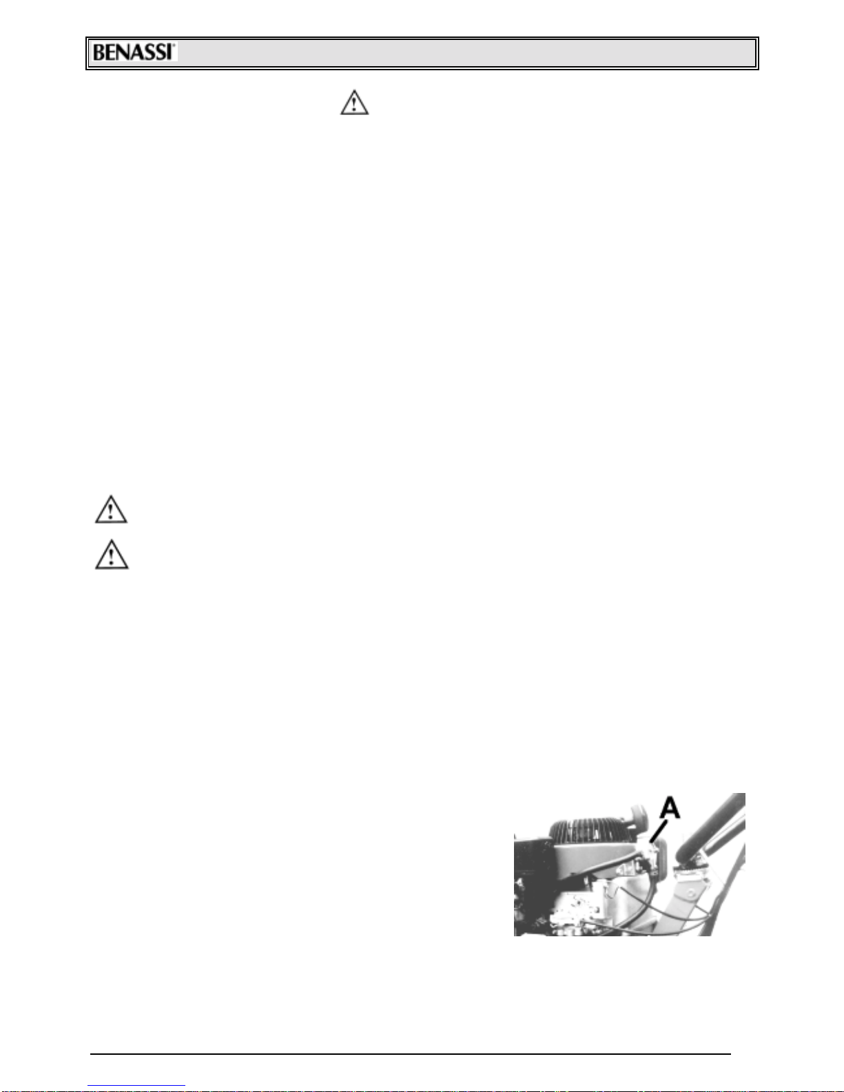
For machine identification (serial number, engine, weight, power) read the data plate as shown in
the photo. See Picture 1,Ref."A".
PACKING AND TRANSPORT
◊WIDTH: 130 cm
◊DEPTH: 80 cm
◊WEIGHT: 80 cm
⇒ The machine is delivered in its own packing.
⇒ The machine is delivered with oil in the gearbox.
⇒ After unpacking the high grass mower, fasten the handle to the handle support using the screws
provided,and adjust the height to the most comfortable position
⇒ Fasten the bumper slide by two screws Ref. 15 of the picture with captions page 2 onto its
supports Ref. C Pics. 5. Lock it in the wished position by means of the knob Ref. A Fig. 5.
⇒ Ensure that the blade engagement lead "D" is not tightened when the blade is disengaged. If it
is tightened,move the register ofthe tightening pulley under the hood Ref. B Pics.2
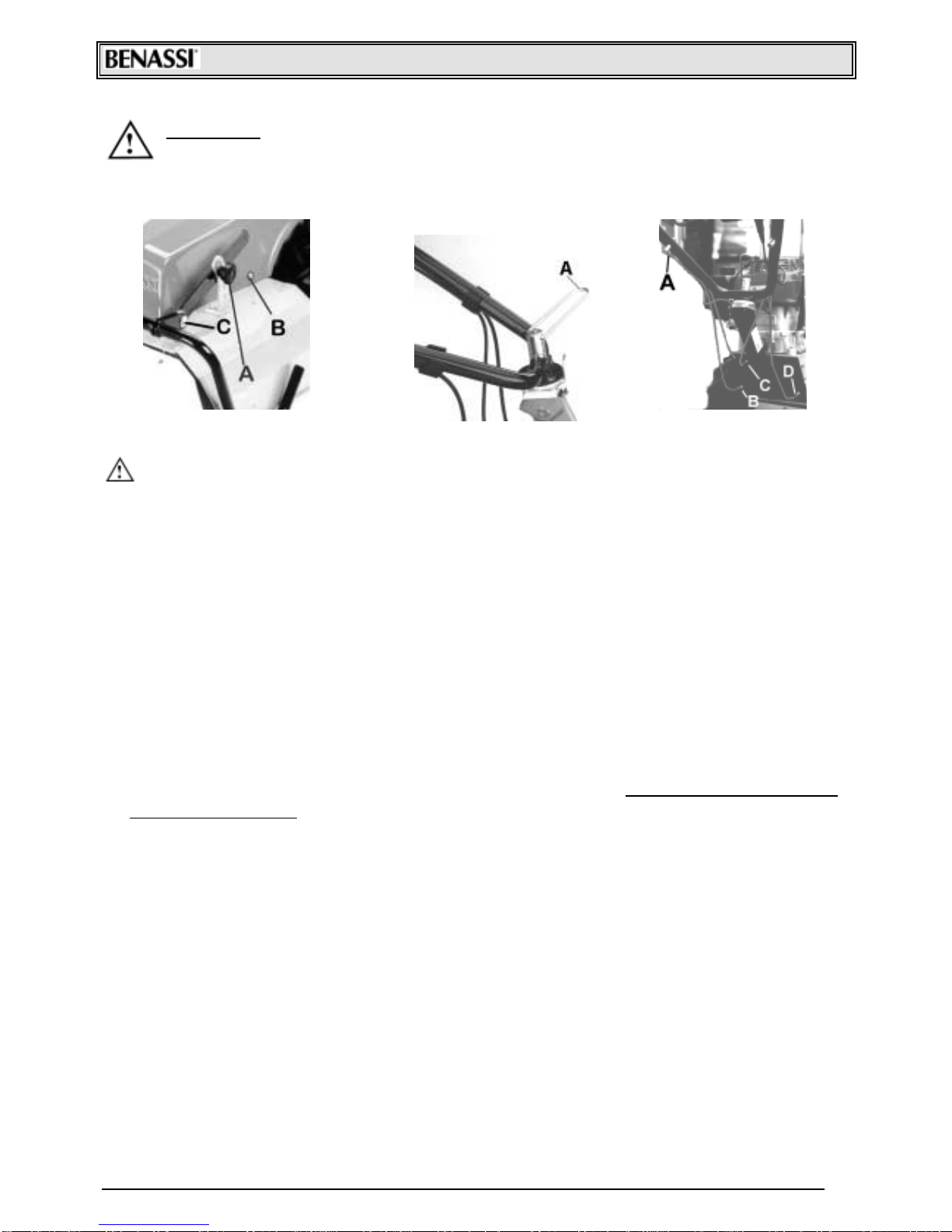
⇒ For transporting convenience, the handle may be disassembled by unscrewing the two knobs
(Ref. "A" Pics 4).
⇒ During the operations oftransport,it is necessary to:
1. disconnect the blade
2. switch off the engine
3. take off the cable of the sparking plug (see ref. 18 in the picture at page 2),in order to prevent
the engine to sw itch on accidentally.
S.p.A. FT 7500
4
SAFETY RULES
• Please read carefully the operation and maintenance manual supplied with the machine.
• Persons under 16 years of age are prohibited from operating the machine.
• The operator is responsible for all damages as the machine is under his control.
• Should the machine be transported,empty the tank ofpetrol.
• Should the machine be left unattended,ensure that it cannot start up again.
• Never work in bare feet. Wear sturdy shoes and long pants.
• Before using the machine, inspect the area to be cut and remove sticks, stones and any other
extraneous objects.
• Before starting the machine, ensure that there is a 5-meter radius of free space around the
machine.
• Dry petrol leaks.
• Always add fuel to the tank with the engine off. The supply and/or the transfer of fuel must
always take place outdoors, away from flames or heat sources. Do not smoke during this
operation.
• Before using the high grass mower, the operator must learn how to shut off the engine quickly,
and how to utilise the machine and the controls correctly.
• Do not operate the engine where carbon monoxide exhaust may accumulate.
• Never utilise the machine incomplete of or without the relative safety device.
• Never disassemble or clean the blade with the engine running.
• CAUTION! Neverworkon slopesexceeding 30°. Pay attention when working in sloping areas. Try
to worktransversally to the slope and never leave the machine unattended when not in flat areas.
• Never leave the blade functioning when moving the high grass mower with the engine
running.
• Neverlift the machine on the side of the operatorwhen the engine isrunning.
• Never start the machine when the operator is on the side of cutting or material discharge point.
• Caution! Always use the front yellow protection
• Cutting shrubs with a diameter of more than 2 cm is not advised.
• The manufacturer shall not be held liable for any damages resulting from the failure to comply
with these rules.
• During blade maintenance and cleaning, the spark plug cable must be disconnected.
STARTING AND STOPPING THE MACHINE
Whenever the engine is started up,first make a careful check of the following:
1. Check that the tank is filled with fuel and the cock is open.
2. Check the engine's oil level.
3. REFER TO THE ENGINE INSTRUCTION AND M AINTENANCE
M ANUAL.
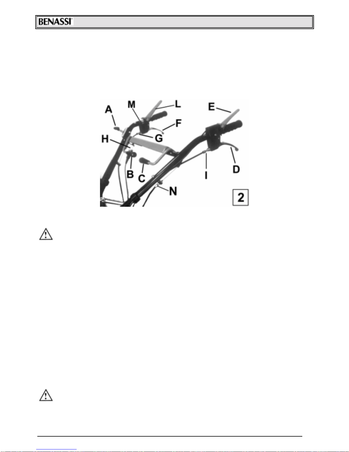
4. Bring the gas lever to START position. (See Pics2 Ref. “A”)
5. Make sure that the lever that engages the blade Ref. “B”
Fig.2 is not engaged
6. Start the engine by pulling the self-winding cord (read
carefully the engine instruction manual under "START-UP"
7. Move the accelerator lever Ref. ”A” Pics.2 back to an intermediate position.
8. The machine will become operational by pushing the "Stop engine" lever (Fig.2 Ref. ”E”) and
pulling at the same tame the blade engagement lever (Fig.2 Ref. ”B”).
- Pics. n 3 -
S.p.A. FT 7500
5
9. To stop the machine, move the lever (Ref. ”A” Fig.2) of the accelerator device to “STOP”
position.
10. To stop the blade in few seconds while keeping the engine running, follow this procedure: hold
the stop lever down Fig.2 Ref. ”E”, move the blade engagement lever Fig.2 Ref. ”B” onto the
disengaged position (toward the engine) while pressing the brake with brake lining. This lever is
equipped with a safety microswitch Fig.2 Ref. ”H” that obliges the operator that wishes to keep
the engine turning with the blade engaged,to hold down the stop engine lever Fig.2 Ref. ”E”.
OPERATING AND REGULATING THE MACHINE
• The FT 7500 machine has been designed to cut and clean very thick grassy and wooded areas.
• The machine is suitable for rugged terrain and for hilly and mountainous areas which do
not,however,have a slope of more than 30°(55%)
• When using the machine on slopes exceeding 15° it is necessary to apply to the machine a petrol
pump kit (only for version with Briggs & Stratton 8,5 HP engine) Ref. “A” Pics 3, that is featured as
an accessory.
• The lever Rif. “L” Fig. 2, is used for engage the first forward speed. In order to engage the second
forward speed, it is necessary to pull the lever “F” fig.2, by keeping the lever “L” fig.2 pushed
down. By releasing only the lever “F” fig.2, first speed is engaged again. This system has been
worked out to help the operator in cutting operations that need the availability of different
speeds. In order to engage the reverse motion, it is necessary to pull the lever Ref.”D” Fig.2.
Attention: don't engage the reverse motion while a forward speed (first or second) is engaged.
• To move the machine in neutral, it is necessary to unlock the wheels by means of the lever Ref.
“C” Fig.2.
• Handlebars are vertically and transversally adjustable and can be blocked in the desired position.
This operation must be carried out by means of the handle (“A” Pics 4).It'sadvised to adjust the
handlebar in the most suitable position according to the slope of the ground.
• Before starting work, adjust the cutting height by means of the cutting height adjusting knob (Pics
5 Ref. “A”). This height varies according to the type of ground, the height of the grass to be cut,
the diameter of the shrubs to be cleaned and the feel of the operator. It is possible to adjust
height in 5 positions.
• When both the blade and the machine start operation, it is advised to move very slowly
with the machine at medium speed.
• If the driving belt slips, loosen the register on the lever (Pics 2 Ref. "M"), taking care to leave a free
space of approximately 5 mm before the forward gear engagement; if it is not enough it is also
possible to adjust the register of Fig.6 Ref.”B”.

S.p.A. FT 7500
6
• If the engagement of the second forward speed is difficult, it is possible to adjust it by means of
the register of the lever Fig.2 Ref.”G”.
• If the belt of the reverse gear slips or tow when disengaged,adjust the registers of Fig2 Ref.”I” or
Fig 6 Ref.”D”.
• It is also possible to register the wheel unlocking device command wire (in case of engaging or
disengaging malfunction), through the register of Fig.2 Ref.”N”. (see Pics.6 Ref.”A”).
• The high grass mower has a double blade,in order to improve the breaking of cut material.
• When the mower is used in open fields or woody areas, it is possible to bring these modifications
to the machine:
1. remove the right side door (ref. A fig. 11);
2. mount the deflector cap (ref. B fig. 12);
3. mark the boundary of the working area as it 's shown in the draft below, before using the
machine. (Respect the measures indicated in the draft);
4. put warning signboards all around the working area. The signboards must report this inscription:
“Danger: throwing objects. Do not cross the enclosure.”
AB
ABCD = 20m X 20m (enclosed area)
A*B*C*D* = 15m X 15m (working area)
C D
Adjustment of the blade pulley belt tightener:
1. Disconnect the spark plug cable (ref. 18 page 2),before starting any operation.
2. Remove the front hood by unscrewing the four screws that fasten the cover (Pics 5 Ref. "B").
3. Engage the blade engagement lever (Pics 2 Ref. "B") so that the belt tightener,located beside
the driving shaft, is in engaged position.
4. Adjust the belt tension (Pics 7 Ref. "A") with the register (Pics 6 Ref. "C")
5. If this adjustment is not effective enough the operator can move the entire cutter assembly
6. Loose the two screws (Pics 7 Ref. “B”) blocking the hexagonal pipe , adjust the register screw
Fig.8 Ref.”A”,to shorten or lengthen de device following needs.
7. Tighten the two screws (Fig.7 Ref.”B”) and check that in brake engaged position the brake with
brake lining (Fig. 7 Ref.”C”), is correctly coupled with the pulley. If not, adjust the brake travel
through the adjustment rod Fig.7 Ref.”D”.
• If the machine has been subjected to heavy use,the discharge may tend to jam. If this happens,
the operator should: 1) raise the cutting height and 2) reduce the working section if the
grass is too high or thick.
• If the high grass mower is used near a wall or sidewalk, take care not to bang the blade as this
could lead to damage to the machine.
A* B*
D* C*
2,5 m
S.p.A. FT 7500
7
CAUTION: It is advised not to keep the engine running when the
machine is not being used for its specific purpose.
-Pics. n°4- - Pics. n°5- - Pics. n°6-
MAINTENANCE
! Before any maintenance or cleaning operation on the high grass mower disconnect the
spark plug cable.
! To change the oil or to perform other maintenance operations on the engine (spark plugs,air
filter, adjustments), refer to the engine instruction manual provided.
! N.B. To unscrew the oil drain cap of the engine, it is necessary to tilt it sideways.
! Make a regular check of the oil in the gearbox (Pics 9 Ref. "C")
! Every 200 hours change the oil completely by unscrewing the oil drain cap (Pics 9 Ref. "B"). Empty
out and screw back the cap. Fill the box from cap "C" (Pics9) until the oil level just reaches the
hole. Use only recommended oil.
! For any servicing, especially during the warranty period, seekthe assistance of a dealer- authorized repair
shop.
! Make a regular check to verify that screws are tightened,specifically the screws fastening the
bar to their support. Ref.”A” Pics 10 and the threaded pins Rif.”B” Fig. 10,that fasten the
articulated blades to the blade support.
! When the blade does not cut adequately,it should be disassembled,sharpened and balanced.
An unbalanced blade may damage the machine with vibrations. . When it is very worn, replace it
with a new original one.
! BLADE SHARPENING OPERATIONS:
8. Disconnect the spark plug cable
9. Unscrew the pins that fasten the blades (Pics10 Ref. “B”)
10.Sharpen the cutting edge area with an emery grinding wheel.
11.Fit the blade paying ATTENTIONto the cutting edge direction of rotation,that is,looking under the
machine, counterclockw ise.
12.Connect the spark plug cable again.

S.p.A. FT 7500
8
-Pics. n°11- -Pics. n°12- -Pics. n°13-
WARRANTY
The machines and accessories are guaranteed for 12 months, with the exception of electrical parts
or parts in rubber. The manufacturer shall replace pieces recognised as defective free of charge.
Labour and transport shall be at the expense of the purchaser. Warranty requests must be made
through dealers authorised by the manufacturer.
With regard to materials not of our manufacture, with special reference to the engine,the rules laid
down by the respective manufacturers shall apply. Any requests for repair shall therefore be directed
to the specific service centres in the respective areas.
For any problem or repair,contact the dealer where the machine was purchased.
-Pics. n°9-
-Pics. n°10-

S.p.A. FT 7500
9
SAFETY TESTS AND CERTIFICATION
Declarationof CE conformity inaccordance w ithEECdirective 89/392 and amendments.
SpA 40010 SanMatteo della Decima BO Italy Via Lampedusa 1
Wehereby declarethat themachineconformswiththeessentialrequirementsforhealthandsafety inaccordance
w ithEEC Directive 89/392 and amendments.
HIGH GRASS MOWERTYPE MODEL FT 7500
CHAIRMAN OF THE BOARD
S. Matteo della Decima
24/02/2000 RESULT AND TESTS
HIGH GRASS MOWERTYPE MODEL FT 7500
Acoustic pressure to the operator: LAeq =89,9 dB (A)
Testing conditions at a height of 1.6 m at handle midpoint.
LWA machine acoustic pow er =101,79 dB (A)
Vibrations w eighted average level measuredaccording to the EN 1033 normand transmitted to the upper limbs:
7,6 m/sec²

S.p.A. FT 7500
10
S.p.A.
Via Lampedusa 1
40010 S. MATTEO DELLA DECIMA (BO)
ITALY
TEL. 051/820534 TELEFAX051/682.61.64
www.benassispa.it e-mail export@benassispa.it
Table of contents
Other Benassi Lawn Mower manuals

Benassi
Benassi FC 200 3VS User manual

Benassi
Benassi FT 530 E User guide

Benassi
Benassi F 1900 series User manual

Benassi
Benassi F 1900 B User manual

Benassi
Benassi F 170 User guide

Benassi
Benassi FC 210 3VS User guide

Benassi
Benassi FT 155 User manual

Benassi
Benassi FT 155 User manual

Benassi
Benassi F 1900 User manual

Benassi
Benassi FT 530 User guide
Popular Lawn Mower manuals by other brands

MTD
MTD 18A-V17-700 Operator's manual

Husqvarna
Husqvarna LB 442i Operator's manual

Toro
Toro Tru Trak Sulky 30110 Operator's manual

Scheppach
Scheppach MP43-40Li Translation from the original instruction manual

Wolf Garten
Wolf Garten 2.34 E Original operating instructions

Craftsman
Craftsman 247.370301 Operator's manual


