Benassi FC 200 3VS User manual

S.p.A.
OPERATION AND
MAINTENANCE MANUAL
SICKLE BAR MOWER
SERIES
ALL VERSIONS
01/07/2008

S.p.A.
2
CONTENTS
INTRODUCTION
DETAILS OF THE MACHINE
IDENTIFICATION AND TECHNICAL
CHARACTERISTICS
PACKING AND TRANSPORT
SAFETY RULES
STARTING AND STOPPING THE MACHINE
OPERATING AND REGULATING THE MACHINE
MAINTENANCE
ACCESSORI
WARRANTY
SAFETY TESTS AND CERTIFICATION
INTRODUCTION
♦Thank you for having selected our product. We would like to welcome you among our many customers.
♦We are certain that you will appreciate the performance and the operating ease of this machine.
♦Our wide experience in the sector, the use of top grade materials and the high quality production ensure the
flawless efficiency of the machine, which is designed to give many years of use if operated and maintained
correctly.
♦We have therefore composed this manual to familiarise you with the use of the machine, its construction,
operating features and applications, which will also facilitate maintenance.
♦Pay special attention to the rules in this manual that are preceded by the symbol below:
CAUTION
♦This symbol indicates that the failure to comply with these rules may lead to personal injury.
DETAILS OF THE MACHINE
1- Accelerator level
2- Engine-stop safety device
3- Clutch lever for wheels
4- Fuel cap
5- Clutch lever for cutter bar
6- Gear lever
7- Handlebar adjustment
8- Tools bag
9- Air filter
10- Side cutter bar
11- Central cutter bar
12- Cutting height adjusting skid
13- Grass divider
14- Oil cap
S.p.A.
3
IDENTIFICATION AND TECHNICAL CHARACTERISTICS
F
OR THE ENGINE FEATURES SEE THE ENGINE INSTRUCTION BOOKLET DELIVERED WITH THE MACHINE
.
•All the engines which can be fitted on this machine have the recoil
starter and protection on the exhaust.
•Fuel for 4-stroke engine : Unleaded petrol
•Fuel for Diesel engine: Diesel oil
•Safety device on handles to stop machine
•Air filter in oil bath
•Consumption at 3600 r.p.m.: 0.8 Kg/hour
•ENGINE LUBRICATION: SAE 30 OIL
•Oil quantity in motor: 0.6 lt.
•Transmission : 2 forward gears + Reverse gear
•TRANSMISSION LUBRICATION : SAE 80W/90 OIL
•Oil quantity in gearbox : 0.5 Kg.
•Manually controlled wheel release and cutting bar
•Steering handles mounted on vibration-damping supports
•"Tractor" type rubber wheels 4.00X8 and rubber wheels 3.50X8
•Central mowing unit
•Manual-control clutch
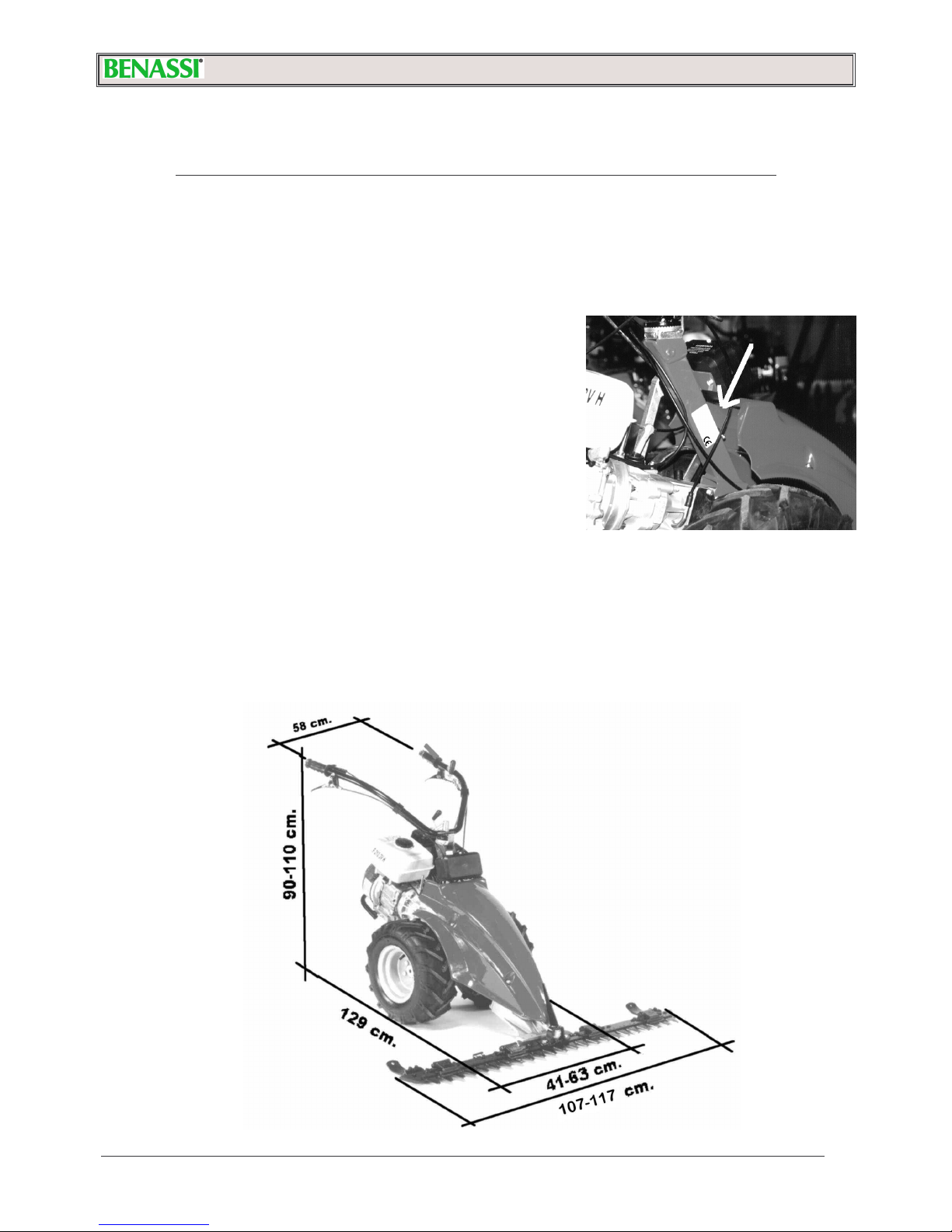
•For machine identification (serial number, motor, weight, power), refer to the data plate as shown in the photo.
See Pict. n.2.

S.p.A.
4
PACKING AND TRANSPORT
WIDTH: 116 cm
DEPTH: 42 cm
HEIGHT: 63 cm
Remove the power mower from its packing.
Secure the handles with the screw (Pict. 10 Ref. “A”). The handle support is secured on anti-vibration devices
(see Pict. 4 Ref. “B”).
Fit the cutter bar into the machine by the quick coupling (see Pict. 6)
If the machine is to be transported, empty out the petrol tank and always apply the plastic protective strip to
the E.S.M. cutting bar blade. Read the E.S.M. sheet attaché.
IMPORTANT: THE PACKED MACHINE IS SUPPLIED WITH THE MOTOR WITHOUT OIL OR PETROL.
SAFETY RULES
•Read carefully the operation and maintenance manual enclosed with the machine.
•The use of the machine is prohibited to persons under 16 years of age.
•The operator is liable for damages since the machine is under his control.
•Those unfamiliar with the machine or who have never used it are obliged to read the operation and
maintenance manual before operation.
•In case of transport, disassemble the bar and empty the petrol out of the tank.
•If the machine is left unattended, ensure that it cannot start up again.
•Before running the machine, the operator must have a 5 meter radius of free space around him.
•Dry any petrol leaks.
•Fill up the tank with the motor off. Filling the tank or transferring fuel must always be performed outdoors, away
from flames or heat sources. Do not smoke during this operation.
•When mowing in mountainous areas or on slopes, mow horizontally and use non-skid equipment on shoes and
wheels.
•If the blade needs replacement, observe E.S.M. operation and maintenance procedures.
•If the bar suffers impact, check the condition of the bar before resuming work.
•Keep feet and hands far away from the cutting bar and all rotating parts.
•Do not run the motor where exhaust containing carbon monoxide may accumulate.
•Never use the mower incomplete or without its safety device.
•Do not assemble/disassemble or clean the cutting bar or other equipment with the motor running.
•Caution! Do not mow areas with slopes exceeding 50%.
•We will not be held liable for accidents caused by the failure to observe these rules.

S.p.A.
5
Every time you get ready to start the motor,
make a careful check of the following:
•Make sure that fuel is in the tank.
•Check engine oil level. IMPORTANT:
ENGINES OF NEWLY MANUFACTURED
MACHINES DO NOT CONTAIN OIL. In this
case, fill with oil up to the oil plug stick.
•CONSULT THE OPERATION AND
MAINTENANCE MANUAL OF THE MOTOR
UNDER "BEFORE START-UP"
•Make sure oil is up to the level in the
gearbox (Pict. 12 Ref. B)
•Check that all safety systems are released and functioning.
•Before starting the machine, when the engine is cold, pull the choke, if it is fitted on your machine.
•Always start the motor up outdoors.
•For versions FC 209 and 210 H 3VS, lower the starter lever (when starting a cold engine), for version FC 200 D 3VS, turn
the lever of the air pump, located above the cylinder head.
•For versions FC 209 and 210 H 3VS, turn the accelerator lever (Pict. 6A Ref. “F”) to “START” position, for the FC 200 D
3VS version, turn the lever by a ¾ turn (Pict. 6B Ref. “F”) . Pull the clutch lever (Pict. 8 Ref. “A”), lower the engine stop lever
(Ref. “C”) and lock it with the push-button (Pict. 8 Ref. “B”). Grip the handle of the self-winding device (Pict. 7), pull gently
until you meet resistance, and then pull it firmly. Do not allow the cord to return to its position on its own, but accompany it
with your hand.
•For best start-up, read the operation and maintenance manual on the motor under "START-UP".
•After starting the engine, disengage the starter lever.
•With the motor running, bring the accelerator lever (Pict. 6A-B Ref. "F") to the middle position.
•To move the mower forward, grip the clutch lever (Pict. 8 Ref. “A”) , select the speed your require with the gear-stick (Pict. 4
Ref. “A”), slowly lower the clutch lever (Ref. “A”), releasing it from the push-button (Pict. 8 Ref. “B”). To engage the mowing
bar, lower the lever (Pict. 8 Ref. “D”) taking care to always do this while the engine is idling. After engaging the bar, you
may accelerate.
•
To move the mower freely forward or back, lift up the wheel release lever (Pict. 8 Ref. “E”).
!
BEFORE STARTING, ALWAYS CHECK IF THE MACHINE IS IDLING AND IF THE CLUTCH HAND-LEVER
IS LIFTED AND LOCKED WITH THE PUSH-BUTTON (Pict. 8 Ref. “A” and “B”).
BEFORE STARTING, THE BAR MUST BE DISABLED BY USING ITS COMMAND (Pict. 8 Ref. “D”).
SAFETY DEVICE FOR STOPPING THE MOTOR
The main function of the lever Ref. "A" Pict. 9 is to turn off the motor when releasing your hands from the steering handles. Do
not ever tie the "MOTOR STOP" lever "A" to the handlebar knob. Before you start to mow, check that the motor shuts off with
the "STOP" lever raised. MOTOR STOP: lever "A" is squeezed; MOTOR START : lever "A" is lowered.
In case of danger the machine will immediately stop after releasing with the left
hand the "stop engine safety device".

S.p.A.
6
OPERATING AND REGULATING THE MACHINE
Before you start mowing, oil the cutting blade, then start the motor as follows:
•The release of the wheels and bar clutches should be done with the engine running at low
speed.
•Engaging the transmission to the wheels and the cutting bar by means of the clutch lever
must be carried out with the motor at a middle r.p.m. and by slowly releasing the lever.
•When starting to mow, position the accelerator lever at 3/4 or at "MAX" to ensure adequate
power.
•When mowing along a wall or the edge of a sidewalk, be careful to keep a safety distance
so that the blade does not suffer impact. If not, the cutting bar may undergo damage.
•When moving forward or back with the mower running, first squeeze the clutch lever which
will block the bar, then squeeze the wheel release lever and move as needed.
•The handles can be adjusted in height and sideways (Pict. 10 Ref. “a”) by a multi-
toothed device.
•You can adjust the cutting height of the grass by the skids on the cutter bar (see
instructions on the bars)
•
To regulate the motor, read the manual on the motor under "REGULATIONS".
•ATTENTION: DO NOT LEAVE THE MACHINE RUNNING WHEN NOT IN
OPERATION
MAINTENANCE
For changing the oil and other maintenance operations on the motor (spark plugs, air filter, regulations), refer to the motor
manual provided.
Make a regular check of the oil level in the gearbox with the cap (Pict. 12 Ref. "b") and topping up if necessary.
Change the oil completely every 200 hours. Empty the gearbox of oil by unscrewing the oil drain plug (Pict. 5 Ref. "C")
Allow oil to flow out completely. Then, screw down the plug completely, and fill with new oil of the recommended type,
unscrewing breather plug (Ref. “A” Fig 12), up to the correct level - see the screw Ref. “B” Fig 12.
If the grass is not cut in a satisfactory manner despite the adjustments (see Pict. 11), the blade must be sharpened or
replaced. Follow the instructions on the E.S.M. maintenance sheet.
For any mechanical repair, especially during the warranty period, we recommend to go to a specialised repair shop of the
dealer.
For transporting convenience, the handles can be disassembled by means of the two knobs (Pict. 10 Ref. "a"). The same is
recommended for the cutting bar, which is easily disassembled by after moving the locking knob (see Pict. 5). Always use
gloves and apply the protective strip to the blade.
Regularly check that screws are tight. Pay special attention to the screws fastening the bar to its support.
Once a year, be sure to check oil level in the bar gearbox (see Pict. 13).
In the types with air filter in oil bath check the oil and clean the filter box every 10 working hours (see Pict. 14).

S.p.A.
7
ACCESSORIES
PAIR OF RUBBER WHEELS 4.00.8
PAIR OF RUBBER WHEELS 16/650.8 (with 50 mm spacers)
PAIR OF IRON WHEELS
PAIR OF “DAISY” TYPE IRON WHEELS (applies to 4.00.8 wheels only)
PAIR OF 50 mm SPACERS FOR WHEELS
PAIR OF 112 mm SPACERS FOR WHEELS
PAIR OF HUBS FOR TWIN-WHEELS
PAIR OF SIDE WINDROWING ATTACHMENTS FOR SEMI-DENSE MOWING UNIT
PAIR OF EXTENSIONS FOR WINDROWING ATTACHMENTS
SNOW PLOUGH 50 x 45 cm
LARGE BRUSH 100 cm
FRONT SNOW-PLOYGH BLADE
TYPE OF BAR :
ESM BAR 117 cm
SPECIAL BAR 107 cm
SEMI-DENSE BAR 112 cm
WARRANTY
The machines and accessories are guaranteed for 2 YEARS, with the exception of electrical parts or parts in rubber. The
manufacturer shall replace pieces recognised as defective free of charge. Labour and transport shall be at the expense of the
purchaser. Warranty requests must be made through dealers authorised by the manufacturer.
With regard to materials not of our manufacture, with special reference to the motor, the rules laid down by the respective
manufacturers shall apply. Any requests for repair shall therefore be directed to the specific service centres in the respective
areas.
For any problem or repair, contact the dealer where the machine was purchased.
IMPORTANT: using the machine for a long time you should use ear protection
system.

S.p.A.
8
SAFETY TESTS AND CERTIFICATION
Declaration of CE conformity in accordance with the directive 98/37 CE and the directive EMC 89/336/CE
S.p.A.
Via Lampedusa n°1 -
40017 San Matteo della Decima BO Italy
We hereby declare that the machine complies with the essential requirements for health and safety in accordance with Directive
98/37/CE.
TYPE: POWER MOWER SERIES: FC 200 3VS MODEL: FC 210 KD 3VS / FC 210 H 3VS
For verification of the conformity with the above-mentioned Directives reference has been made to following specifications: UNI
EN ISO 12100-1 and UNI EN ISO 12100-2; UNI EN 12733 for pushed motor mowers with rotating cutting blades or with
reciprocating motion used in agriculture, forestry and horticulture.
CHAIRMAN OF THE BOARD
S.Matteo della Decima 18/10/2007
RESULT AND TESTS
TYPE: POWER MOWER MODEL: FC 210 KD 3VS / FC 210 H 3VS
Acoustic power level LwA = from LdB (A) 104 to 109 LdB (A)
Acoustic pressure to the operator’s ear: LpA = from 91,5 dB (A) to 99,4 dB (A)
Testing conditions height 1.6 m handle midpoint.
Vibration to handles with weighting UNI EN 1033-1 value: from 14,9 m/sec2 to 24,61 m/sec2.
This declaration of CE conformity is valid only if the product doesn’t undergo any changes or modifications without authorization.
S.p.A.
VIA LAMPEDUSA 1
40017 S. MATTEO DELLA DECIMA (BO) – ITALY
TEL. +39/051/820534 TELEFAX +39/051/820526
Web: www.benassi.eu e-mail: export@benassispa.it
Dealer stamp
Table of contents
Other Benassi Lawn Mower manuals

Benassi
Benassi ft 7500 Manual

Benassi
Benassi FT 530 User guide

Benassi
Benassi F 1900 User manual

Benassi
Benassi F 1900 series User manual

Benassi
Benassi FT 155 User manual

Benassi
Benassi F 1900 B User manual

Benassi
Benassi FT 530 E User guide

Benassi
Benassi F 170 User guide

Benassi
Benassi FT 155 User manual

Benassi
Benassi FC 210 3VS User guide


