Bend-Pak Autostacker PL-6SR User manual
1645 Lemonwood Dr.
Santa Paula, CA, 93060 USA
Toll Free (888) 977-8225
Tel: (805) 933-9970
autostacker.com
Autostacker™ Parking Lift
Installation and Operation Manual
Manual P/N 5900002 — Manual Revision D — August 2019
Models:
• PL-6SR
• PL-6SRX
U.S. Design Patent No. D814,736
Autostacker is designed and engineered by BendPak Inc. in Southern California, USA. Made in China.
⚠
DANGER
Read the
entire
contents of this Manual
before
using this product. Failure
to follow the instructions and safety precautions in this manual can result in
serious injury or death. Make sure all other operators also read this manual. Keep
the manual near the product for future reference. By proceeding with setup and
operation, you agree that you fully understand the contents of this manual.
Manual. Autostacker Parking Lift, Installation and Operation Manual, Manual P/N 5900002, Manual Revision D,
Released August 2019.
Copyright. Copyright © 2019 by BendPak Inc. All rights reserved. You may make copies of this document if you
agree that: you will give full attribution to BendPak Inc., you will not make changes to the content, you do not gain
any rights to this content, and you will not use the copies for commercial purposes.
Trademarks. BendPak and the BendPak logo are registered trademarks of BendPak Inc. Autostacker is a
trademark of BendPak Inc. All other company, product, and service names are used for identification only. All
trademarks and registered trademarks mentioned in this manual are the property of their respective owners.
Limitations. Every effort has been made to ensure complete and accurate instructions are included in this
manual. However, product updates, revisions, and/or changes may have occurred since this manual was
published. BendPak reserves the right to change any information in this manual without incurring any obligation for
equipment previously or subsequently sold. BendPak is not responsible for typographical errors in this manual.
You can always find the latest version of the manual for your product on the Autostacker website.
Warranty. The Autostacker warranty is more than a commitment to you: it is also a commitment to the value of
your new product. For full warranty details, contact your nearest Autostacker dealer or visit
autostacker.com/support/warranty.
Safety.Your product was designed and manufactured with safety in mind. Your safety also depends on proper
training and thoughtful operation. Do not set up, operate, maintain, or repair the unit without reading and
understanding this manual and the labels on the unit;
do not use this product unless you can do so
safely!
Owner Responsibility. In order to ensure operator safety and maintain your product properly, it is the
responsibility of the product owner to read and follow these instructions:
• Follow all setup, operation, and maintenance instructions.
• Make sure product setup conforms to all applicable local, state, and federal codes, rules, and regulations,
such as state and federal OSHA regulations and electrical codes.
• Read and follow all safety instructions. Keep them readily available for operators.
• Make sure all operators are properly trained, know how to safely operate the unit, and are properly supervised.
• Do not operate the product until you are certain that all parts are in place and operating correctly.
• Carefully inspect the product on a regular basis and perform all maintenance as required.
• Service and maintain the unit only with approved replacement parts.
• Keep all instructions permanently with the product and make sure all labels are clean and visible.
• Only use this product if it can be used safely!
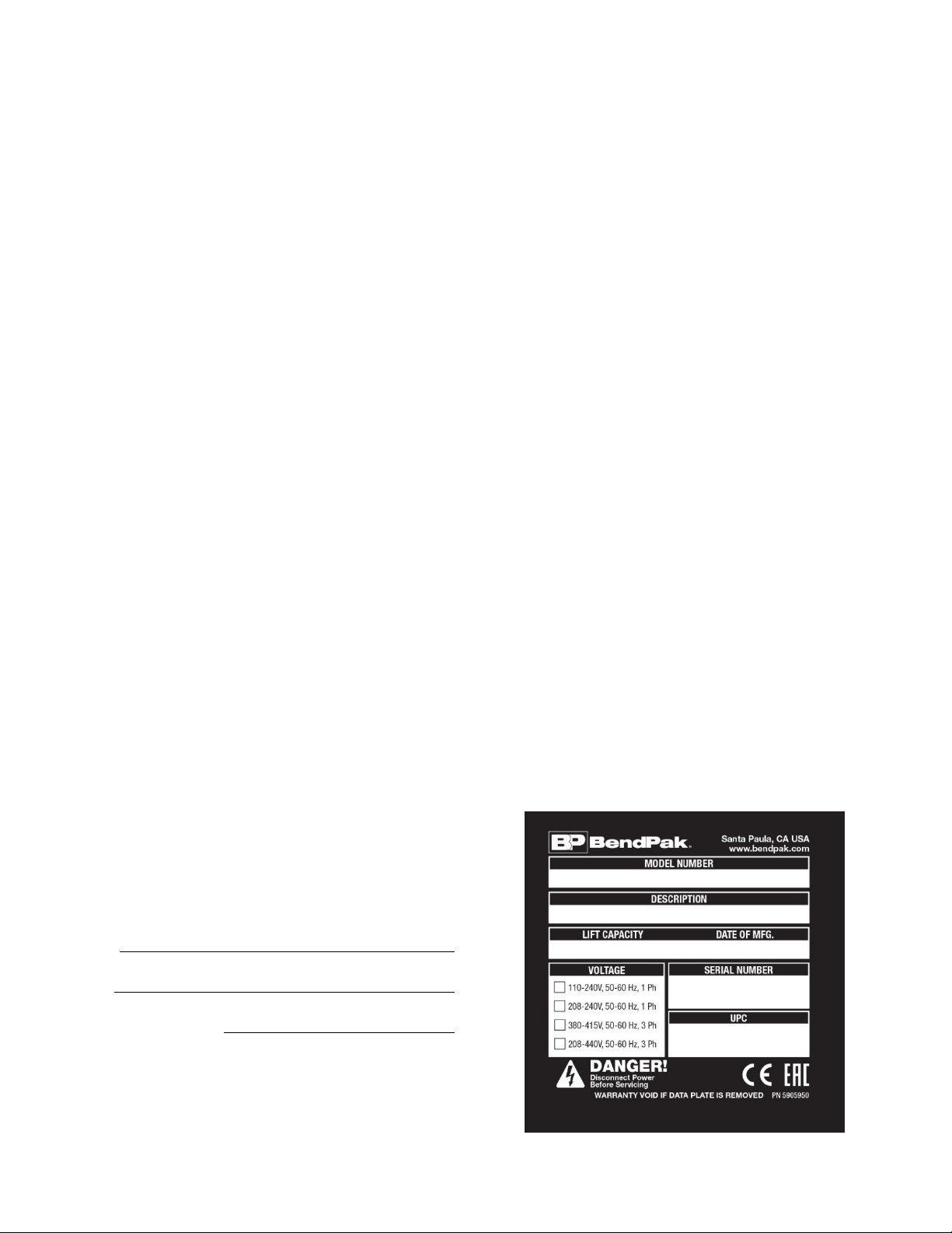
Unit Information. Enter the Model Number, Serial
Number, and the Date of Manufacture from the label
on your unit. This information is required for part or
warranty issues.
Model:
Serial:
Date of Manufacture:

Autostacker™ Parking Lift 3P/N 5900002 — Rev. D — August 2019
Table of Contents
Introduction 3 Installation 13
Shipping Information 4 Operation 41
Safety Considerations 4 Maintenance 47
FAQ 6 Troubleshooting 48
Specifications 7 Multi-Autostacker 51
Components 8 Wiring Diagrams 68
Will My Cars Fit? 10 Labels 74
Orientation 11 Parts Diagrams 80
Installation Checklist 12
Introduction
This manual describes both Autostacker versions, which can easily and quickly raise a Vehicle so that
you can park a second Vehicle underneath.
Autostacker raises Vehicles up to 6,000 lbs (2,722 kg). For more information about Autostacker, visit
autostacker.com.
Autostacker is available in two versions:
•PL-6SR. Parking Lift that allows you to make a parking spot that holds just one Vehicle into a
parking spot that holds two Vehicles, lifting vehicles up to 6,000 lbs (2,722 kg).
•PL-6SRX. Wide version of the PL-6SR, with an extra 8 inches of width for your Vehicles.
Autostacker is available in a
Multi-Lift
configuration, where you can control up to 12 Lifts using a
single Master Power Unit.
Unless specifically stated, the setup for each Autostacker in a Multi-Lift configuration follows the same
installation process as a single Autostacker. The main differences include separate procedures for
routing the Hydraulic Hoses and Return Line to a Master Power Unit, in addition to installing a Control
Stand to each Lift that allows you to operate a specific Lift in your lineup; see Multi-Autostacker
towards the end of this manual for those modified procedures and any additional information.
After you have completed those modified procedures, continue the remainder of the installation as you
would with a single Autostacker; see the Installation Checklist for an overview of the installation
process.
This Manual is mandatory reading for
all Autostacker Lift installers and users
.

Autostacker™ Parking Lift 4P/N 5900002 — Rev. D — August 2019
⚠DANGER Be very careful when setting up, operating, maintaining, or repairing this equipment;
failure to do so could result in property damage, product damage, injury, or (in very
rare cases) death. Make sure only authorized personnel operate this equipment. All
repairs must be performed by an authorized technician. Do not make modifications
to the unit; this voids the warranty and increases the chances of injury or property
damage. Make sure to read and follow the instructions on the labels on the unit.
Keep this manual on or near the equipment so that anyone who uses or services it can read it.
Technical support for your product is available directly from your distributor or you can contact
parts (please have the serial number and model number of your unit available).
Shipping Information
Your equipment was carefully checked before shipping. Nevertheless, you should always thoroughly
inspect the shipment before you sign to acknowledge that you received it.
When you sign the bill of lading, it tells the carrier that the items on the invoice were received in good
condition.
Do not sign the bill of lading until
after
you have inspected the shipment.
If any of the
items listed on the bill of lading are missing or damaged, do not accept the shipment until the carrier
makes a notation on the bill of lading that lists the missing and/or damaged goods.
If you discover missing or damaged goods
after
you receive the shipment and have signed the bill of
lading, notify the carrier at once and request the carrier to make an inspection. If the carrier will not
make an inspection, prepare a signed statement to the effect that you have notified the carrier (on a
specific date) and that the carrier has failed to comply with your request.
It is difficult to collect for loss or damage after you have given the carrier a signed bill of lading. If this
happens to you, file a claim with the carrier promptly. Support your claim with copies of the bill of
lading, freight bill, invoice, and photographs, if available. Our willingness to assist in helping you
process your claim does not make us responsible for collection of claims or replacement of lost or
damaged materials.
Safety Considerations
Read this manual carefully before using your new product.
Do not set up or operate
the product until you are familiar with all operating instructions and warnings. Do not allow anyone else
to operate the product until they are also familiar with all operating instructions and warnings.
General Safety Information
Please note the following:
•The product is a Parking Lift. Use it only for its intended purpose. Do not make any
modifications.
•The product must only be operated by authorized personnel.
•Always wear appropriate protective clothing when installing, servicing, or repairing your
Autostacker.

Autostacker™ Parking Lift 5P/N 5900002 — Rev. D — August 2019
•Keep loads centered and balanced on the Platform. Do not overload the rear side; Autostacker is
designed to support an equal load.
•Use caution when driving onto the Platform with a Vehicle with wet tires.
•When the product is in use, keep all body parts away from it.
•Do not leave the area or the Autostacker without confirming that each Leg Base is secured on a
Safety Lock.
•Make sure all operators read and understand the Installation and Operation Manual. Keep the
manual near the device at all times.
•Make a visual inspection of the product before using it. Check for damaged or missing parts. Do
not use the product if you find any issues. Instead, take it out of service, then contact your
distributor, or Autostacker at autostacker.com/support or support@autostacker.com.
•Make a thorough inspection of the product at least once a year. Replace any damaged or severely
worn parts, decals, or warning labels.
Symbols
Following are the symbols used in this manual:
⚠DANGER Calls attention to an immediate hazard that will result in injury or death.
⚠WARNING Calls attention to a hazard or unsafe practice that could result in injury or death.
⚠CAUTION Calls attention to a hazard or unsafe practice that could result in minor personal
injury, product, or property damage.
NOTICE Calls attention to a situation that, if not avoided, could result in product or property
damage.
Tip Calls attention to information that can help you use your product better.
Liability Information
BendPak Inc. assumes no liability for damages resulting from:
• Use of the product for purposes other than those described in this manual.
• Modifications to the equipment without prior, written permission from BendPak Inc.
• Damage to the equipment from external influences.
• Incorrect operation of the equipment.

Autostacker™ Parking Lift 6P/N 5900002 — Rev. D — August 2019
Frequently Asked Questions
Question: What kinds of Vehicles is Autostacker designed for?
Answer: Autostacker is designed for cars, light trucks, and SUVs.
Q: Why is the Platform angled?
A: The angled Platform allows low-profile Vehicles to drive directly onto the Platform without scraping.
Q: How high does my garage ceiling have to be to use Autostacker?
A: Autostacker works great with ceilings as low as 10 feet. However, the height of the ceiling does
impact what cars you can park on the Lift. Refer to Will My Car Fit? for complete information.
Q: Can I put the Console on either side of the Autostacker?
A: Yes. The included Hydraulic Hoses are long enough to support the Console being up to 30 inches
away on either side. If you want, you could go to your local hydraulics shop and get longer, custom-
made Hydraulic Hoses that give you greater latitude for where you put your Console. Remember that
the operator
must
be able to see both the Autostacker and the area around it, for safety purposes.
Make sure to cover the Hydraulic Hoses once they are installed.
Q: Does it matter if I drive my vehicles in straight or back them in?
A: No, Autostacker works great either way. For the Vehicle
on
the Platform, make sure the wheels are
in the Tire Trough, whichever direction you drive it on. For the Vehicle
under
the Platform, put it in
whichever direction makes it easier to open the doors. Note that it is not required that you drive your
under Vehicle all the way underneath the Platform; for some Vehicles, opening the doors is easier if you
only drive part way in.
Q: Can Autostacker be installed outside?
A: Yes, but the Lift is designed for indoor installation, so there are some additional things you will need
to do; cover the Console, put a canopy over the Lift, keep it clean and dry, and increase maintenance.
Contact BendPak Customer Service (via the web bendpak.com/support, via email
techsupport@bendpak.com, or via phone (800) 253-2363 for additional information.
Q: How long can I leave a Vehicle raised on the Autostacker?
A: As long as you want,
if it is engaged on a Safety Lock
. Autostacker is great for storage in any
condition, long or short-term.
Q: Can I change the oil on the Vehicle raised on the Autostacker?
A: Yes; the optional Access Panel gives you access to the underside of the Vehicle that is raised,
making your parking lift into a service lift as well. Each Access Panel works in place of three Platform
sections and you can install up to two access panels per Autostacker.
Q: How many Lifts can be supported by the Master Power Unit?
A: The Master Power Unit can support up to 12 Autostacker Lifts, although
only one Lift can be
raised and lowered at a time
.

Autostacker™ Parking Lift 7P/N 5900002 — Rev. D — August 2019
Specifications
Specifications PL-6SR PL-6SRX
Lifting capacity 6,000 lbs. / 2,722 kg
ATotal width 103" (8.6 feet) / 2,620 mm 111" (9.3 feet) / 2.815 mm
BPlatform width 83.75" (7 feet) / 2,127 mm 91.75" (7.7 feet) / 2,331 mm
CDrive-thru width 83" (7 feet) / 2,112 mm 90.75" (7.7 feet) / 2,305 mm
DOverall length 143" (12 feet) / 3640 mm
EPlatform plus ramp 143" (12 feet) / 3,632 mm
Platform only 129" (10.7 feet) / 3,274 mm
Maximum wheelbase 132" (11 feet) / 3,352 mm
Maximum underclearance 80" (6.7 feet) / 2,032 mm
Top Safety Lock 81" (6.9 feet) / 2,057 mm
Ramp height 2" / 50.75 mm
Rise/Lower Speed 55 seconds / 35 seconds
Motor • 220 VAC at 50 Hz, 208-230 VAC at 60 Hz, 1 Ph
• 380 VAC at 50 Hz, 3 Ph
• 110 VAC at 50/60Hz, 1 Ph
If you have a
Multi-Lift
setup, see Multi-Autostacker for modified specifications.

Autostacker™ Parking Lift 8P/N 5900002 — Rev. D — August 2019
Components
Autostacker components include:
•Console. Hosts the Controls for your Autostacker and the Power Unit. The Console is designed
to go on either side of the front of the Autostacker. The included Hydraulic Hoses let you put the
Console up to 30 inches away from the Autostacker. For a Single-Lift setup.
•Platform. Angled metallic deck that holds Vehicles. The Platform has the Tire Trough at one end
(the front) and the Drive-Up Ramp at the other end (the back).
•Drive-Up Ramp. Gives you access to the Platform. Note that the Tires of the Vehicle you are
parking on the Platform can be placed on the Drive-Up Ramp.
•Tire Trough. Lowered section of the Platform that holds the Vehicle’s tires. The Tire Trough
functions as tire chocks, so it is very important that the wheels of the Vehicle sit fully in the Tire
Trough.
•Patented Door-sentry™ car door protectors. Protects the car doors of the Vehicle parked
under the Platform. You should carefully open the car doors of the Vehicle parked under the
Platform, but the car-door protectors are there in case of contact.
•Leg Assemblies. The Autostacker comes partially assembled, making installation easier and
faster. There are two Leg Assemblies, left and right. Each Leg Assembly has a Platform Arm, Leg,
Cylinder, and Base. Note that the two Leg Assemblies are heavy and can damage materials like
tile, sandstone, and brick if not handled correctly; you must use a lifting device like a Forklift or
Shop Crane to move the Leg Assemblies.
•Left and Right Legs. Part of a Leg Assembly, they raise and lower the Platform.
•Safety Locks. Hold the Platform in place while it is raised. Multiple Safety Locks let you select
the right Platform height for your needs.
Only leave your Autostacker on the ground or
on the Safety Locks.
•Top Safety Lock. Provides the most space for the Vehicle under the Platform. The heights of all
six Safety Locks are listed in Raising a Vehicle.
•Lowest Safety Lock. Provides the most space for the Vehicle on the Platform.
•Left and right Cylinders. Also part of a Leg Assembly, they move the Legs up and down using
hydraulic power. The Cylinders are synchronized so that raising and lowering the Platform is even,
smooth, and rapid.
•Top and Bottom Connector Tubes. Located at the front of the Lift, the Connector Tubes
hold the Autostacker superstructure together. The Bottom Connector Tube is hollow; the Hydraulic
Hoses and the Return Lines are routed to the Console through the Bottom Connector Tube.
•Hydraulic Hoses. The Hydraulic Hoses provide hydraulic power to the Hydraulic Cylinders,
which they use to raise and lower the Lift.
•Return Line. Returns extra Hydraulic Fluid to the reservoir on the Power Unit. Connect to the top
of the Hydraulic Cylinders.
•Velocity Fuse. Prevents the Hydraulic System from failing in the event of a sudden, catastrophic
loss of Hydraulic Fluid pressure; if a Hydraulic Hose were accidentally cut, for example, while the
Platform was raised with a Vehicle on it.
•Rubber Padding. Offers padded protection if you accidentally bump your head into the Platform
Arm when passing underneath the Platform. One per Leg Assembly.
•Conduit Tube. Not shown. Used for routing electrical wiring if you have a Control Stand at the
Rear of the Lift. For a Multi-Autostacker setup; see Multi-Autostacker for additional information.
•Control Stand. Not shown. Holds the Controls to operate a specific Lift in a Multi-Lift setup, and
can be placed at the Front or Rear of the Lift. See Multi-Autostacker for additional information.
•Safety Placard. Not shown. Includes safety and operation instructions; attaches to the Control
Stand. See Multi-Autostacker additional information.

Autostacker™ Parking Lift 9P/N 5900002 — Rev. D — August 2019
The following drawing shows the two possible locations for the Lift Controls: The Console for a
Single-Lift configuration versus the Control Stand for a Multi-Lift configuration.
Console:
Control Stand:

Autostacker™ Parking Lift 10 P/N 5900002 — Rev. D — August 2019
Will My Cars Fit?
The Autostacker accommodates a wide variety of cars, light trucks, and SUVs. This section describes
how to get wider, longer, and taller Vehicles onto your Autostacker.
Width
Considerations for Vehicle width include:
•Platform width. The width from the outside of the left tires to the outside of the right tires cannot
exceed the width of the Platform. The tires
must
fit on the Autostacker Platform.
•Mirrors. Mirrors and other accessories may mean that some parts of a Vehicle are much wider
than the tires of the Vehicle. This is generally not a problem on a raised Vehicle, but should be
taken into consideration for Vehicles being parked under the Autostacker.
•Doors. Opening car doors makes the Vehicle wider while they are open. If opening Vehicle doors
is an issue, try driving in the Vehicle in the other direction. Autostacker Legs have Door-sentry car
door protectors, which limit problems if a door does contact an Autostacker Leg.
Length
Considerations for Vehicle length include:
•Vehicle wheelbase. Vehicles that get raised on the Platform must have one set of wheels in the
Tire Trough and the other set on the Platform itself.
•Overhang. If a Vehicle’s wheelbase fits on the Platform, then any overhanging parts of the Vehicle
outside the wheelbase are not an issue.
Height
Considerations for Vehicle height include:
•Ceiling height. The height of the ceiling determines how much space you have for the two
Vehicles. If you want to park both a tall Vehicle on and under your Autostacker, your ceiling needs
to be higher than if you want to park two low-slung Vehicles.
•Formula. There’s a formula for figuring out how high a ceiling you need.
Height of Vehicle on Platform +16 inches +Safety Lock height
For example: Say you have a 2017 Camaro and a 2017 Toyota Camry. The Camry is 58 inches
high, the Camaro is 53 inches. If you want the Camry under the Platform and the Camaro on it, the
formula would be 53 +16 +65.75 (fourth Safety Lock) = 134.75 inches. If you have a 12 foot high
ceiling, you have 144 inches to use, so this combination would fit fine.
The 16 inch figure includes the height of the Platform plus the height needed to raise the Lift off of
the Safety Lock. Note this figure is a rough estimate, for calculation purposes only.
⚠CAUTION We recommend double checking your ceiling and Vehicle heights before raising a
Vehicle on the Autostacker Platform.
Be especially vigilant the first time
you raise a particular Vehicle!
No one wants to see the roof of their Vehicle
make contact with the ceiling. Use the Emergency Stop button if necessary.
Autostacker™ Parking Lift 11 P/N 5900002 — Rev. D — August 2019
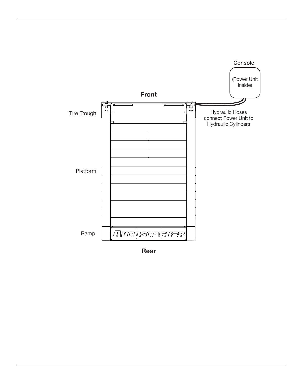
Orientation
The following diagram shows the Console on the right side; it can be placed on either side up to 30
inches away from the Lift.
Not all components are shown. Drawing not necessarily to scale.

Autostacker™ Parking Lift 12 P/N 5900002 — Rev. D — August 2019
Installation Checklist
Following are the steps needed to install an Autostacker; perform them in this order.
☐1. Review the installation Safety Rules.
☐2. Make sure you have the necessary Tools.
☐3. Plan for Electrical Work.
☐4. Select the installation site.
☐4. Check Clearances around the Lift.
☐5. Create a floor plan.
☐6. Position the Leg Assemblies and other components.
☐7. Attach the Bottom and Top Connector Tubes.
*
☐8. Anchor the Bases to the ground.
☐9. Set up the Console and attach the Power Unit.
*
☐10. Connect the Hydraulic Hoses.
*
☐11. Connect the Return Lines.
*
☐12. Connect the Power Unit.
*
☐12. Attach the Conduit Tube.
*
☐12. Install the Control Stands.
*
☐13. Wiring a Power Disconnect Switch.
☐14. Install a Thermal Disconnect Switch.
☐15. Test the Autostacker.
☐16. Add the Tire Trough and Tire Stops.
☐17. Add the Platform sections and Drive-Up Ramp.
☐18. Lubricate the Autostacker.
☐19. Review the Final Checklist.
*
Procedures modified and/or specific to a
Multi-Lift
configuration only. See Multi-Autostacker for
more information.

Autostacker™ Parking Lift 13 P/N 5900002 — Rev. D — August 2019
Installation
This section describes how to install your Autostacker. Perform the steps in the order listed.
⚠WARNING
Only use the factory-supplied parts that came with your Lift
. If you
use parts from a different source, you void your warranty and compromise the
safety of everyone who installs or uses the Lift. If you are missing parts, visit
autostacker.com/support or call (888) 977-8225.
Safety Rules
When installing your Autostacker, your safety depends on proper training and thoughtful operation.
⚠WARNING Do not install this equipment unless you have automotive lift installation training.
Always use proper lifting tools, such as a Forklift or Shop Crane, to lift heavy
components. Do not install this equipment without reading and understanding
this manual and the safety labels on the unit.
Only fully trained personnel should be involved in installing this equipment.
Pay attention at all
times.
Use appropriate tools and lifting equipment, when needed. Stay clear of moving parts.
BendPak recommends referring to the current version of the ANSI/ALI ALIS Standard Safety
Requirements for Installation and Service for more information about safely installing, using, and
servicing your Lift.
⚠WARNING You must wear appropriate protective equipment
at all times
during
installation: gloves, steel-toed work boots, eye protection, back belts, and
hearing protection.
Tools
You may need some or all of the following tools:
•Rotary hammer drill or similar
•3/4", 3/8" masonry bits
•Hammer and crow bar
•Open-end wrench set
•Socket and ratchet set
•Medium crescent wrench
•Chalk line and tape measure
•Medium flat screwdriver
•Fork lift or Shop Crane

Autostacker™ Parking Lift 14 P/N 5900002 — Rev. D — August 2019
Electrical Work
You will need to have a licensed, certified Electrician available at some point during the installation.
⚠DANGER All wiring
must
be performed by a licensed, certified Electrician.
The Electrician needs to do these things:
•Connect the selected power source to the bottom of the Power Disconnect
Switch. Required. This is generally done when the Power Unit is being connected.
•Connect the Power Unit to the top of the Power Disconnect Switch. Required. This is
generally done when the Power Unit is being connected.
•Install a
Thermal
Disconnect Switch. Optional. BendPak recommends connecting a
Thermal Disconnect Switch or overload device (not supplied) to make sure the equipment shuts
down in the event of an overload or an overheated motor. Refer to Install a Thermal
Disconnect Switch for more information.
Select a Site
Keep the following in mind when selecting a site for your Autostacker:
•Enough space. Make sure there is adequate space for the Autostacker on all four sides, plus
enough height for the Vehicles you will be lifting. If architectural plans are available, use them to
make sure there is adequate space for your planned layout.
•No overhead obstructions. Make sure the site is free of overhead obstructions such as
heaters, building supports, electrical lines, lights, and so on.
•Concrete specifications. Do not install the lift on cracked or defective Concrete. Make sure
the concrete is at least 4.25 inches thick, 3,000 psi, and cured for at least 28 days if recently
poured. Make sure the floor is defect-free, dry, and level.
⚠WARNING Do not install your Autostacker on a surface with 3° or more of slope. A 3° degree
slope or greater could lead to property damage, personal injury, or death.
•Power. You will need a power source available near the Console. For a 220 VAC, single-phase
circuit, use a 25 amp or greater fuse. For a 380 VAC, three-phase circuit, use a 20 amp or greater
fuse.
•Operating temperature. Autostacker is designed to be used between temperatures of 0°F to
104°F (-20°C to 40°C).
•Indoor installation. Autostacker is designed for indoor installations.
•Outdoor installation. Autostacker is not designed for outdoor use. It has an operating ambient
temperature range of 0ºF to 104ºF (-20ºC to 40ºC). If operation below this temperature is required,
contact autostacker.com/support for more information. Do not operate your Autostacker in
rain or extremely damp locations. It is water resistant, not waterproof, and water damage is not
covered under the warranty. Outdoor installations can be accommodated in certain regions
if
optional moisture preventative devices are ordered and installed. Coastal locations often require
additional maintenance due to highly corrosive airborne ocean salt. Although parts of your Lift are
made of galvanized metal and protected by commercial-grade powder coat, take additional
precautions by damp washing all exposed surfaces approximately every three months. Do not
allow grass clippings, leaves, or other debris to accumulate on your Autostacker. If you use your
Autostacker outdoors, clean it daily and lubricate it every week.
•Second floor installs. Do not install the Autostacker on a second floor or elevated floor without
first consulting the building architect and getting their approval.

Autostacker™ Parking Lift 15 P/N 5900002 — Rev. D — August 2019
•Dress properly. Wear protective gear (like safety goggles, helmet, heavy gloves, suitable
working clothes, safety boots, ear protection, and so on) when installing Autostacker. Do not wear
loose clothing or jewelry; contain long hair; keep hair and clothing away from moving parts.
⚠WARNING
Always
wear appropriate protective gear when working on the Autostacker.
Important: Your Autostacker Lift is supplied with installation instructions and concrete fasteners
that meet the criteria set by the current American National Standard “Automotive
Lifts – Safety Requirements for Construction, Testing, and Validation” ANSI/ALI
ALCTV. Lift buyers are responsible for any special regional, structural, or seismic
anchoring requirements specified by any other agencies or codes, such as the
Uniform Building Code or International Building Code.
Create a Floor Plan
You need to plan out, in advance, where the Autostacker is going to go. Be sure to work with the
Autostacker owner on this:
•Access. The Autostacker is a Parking Lift, so be sure you can drive Vehicles onto it.
•Side clearance. Consider whether or not you want enough room on the sides for people to walk
around the Autostacker.
•Front clearance. Vehicles parked on the Autostacker Platform may extend over the front. If the
Vehicle you want to place on the Platform is longer than average (a light truck or a Cadillac, for
example), make sure you have enough room between the Autostacker and any obstacles (such as
a wall).
•Rear clearance. You are not required to park the Vehicle under the Autostacker all the way
underneath the Platform. Depending on the Vehicle, it may be easier to get in to and out of the
Vehicle if you only go partway under the Platform, as shown below. If this is a consideration, make
sure to allow adequate room at the rear of the Autostacker (the drive-up end) for you to park the
Vehicle and for the garage door to close.
This image shows an Autostacker using some of the space at the rear (by the garage door) for the
Vehicle underneath the Platform to be only partway in.

Autostacker™ Parking Lift 16 P/N 5900002 — Rev. D — August 2019
•Console. The Console must be located near the Autostacker; the Hydraulic Hoses that come with
the Autostacker are optimized for up to 30 inches between the Autostacker and the Console.
Tip If you want the Console further than 30 inches from the Autostacker, you can use
custom Hydraulic Hoses. Keep in mind that the Console
must
have a full,
unobstructed view of the Autostacker and be near the power source.
•Operator. The operator at the Console must have a full, unobstructed view of the Autostacker.
•Power. The Console must also be positioned near the power source.

Autostacker™ Parking Lift 17 P/N 5900002 — Rev. D — August 2019
Create Chalk Lines Guides
Using Chalk Line Guides makes it easy to position the Autostacker components for installation.
Note: The front of the Autostacker is the end
opposite
the Drive-Up Ramp. The Tire Trough is at
the front of the Autostacker and the Drive-Up Ramp is at the back.

Autostacker™ Parking Lift 18 P/N 5900002 — Rev. D — August 2019
To add Chalk Line Guides:
1. Decide where you want to place the Autostacker.
2. Create an Alignment Chalk Line where you want the front of the Autostacker.
Make the Alignment Chalk Line
longer
than the Total Width setting for the Autostacker.
3. Create two perpendicular chalk lines at 90° angles to the Alignment Chalk Line.
Make the distance between the Left Side Chalk Line and the Right Side Chalk Line the distance of
the Total Width setting for the Autostacker, found in Specifications.
For a
Multi-Lift
setup, see Multi-Autostacker for modified specifications. If you plan to
position the Control Stand at the
Rear
of the Lift, use the Total Width (A); do not use the A1 figure.
4. When you want to move the components into position, put the Bottom Connector Tube against
the Alignment Chalk Line and between the Left and Right Side Chalk Lines.
Put the Leg Assemblies up against the Bottom Connector Tube and inside the Left and Right Side
Chalk Lines, respectively.
The Leg Assemblies are
not
interchangeable; the Door Sentry car-door protectors go on the
inside.

Autostacker™ Parking Lift 19 P/N 5900002 — Rev. D — August 2019
Position the Autostacker Components
When the Lift components are delivered to the site, try to have them placed near where you will be
installing the unit. For example, if you are installing Autostacker in a garage, you might want to have the
components unloaded on the garage’s driveway or inside the garage.
⚠CAUTION Some of the Autostacker components are heavy and can damage materials like tile,
sandstone, and brick if not handled correctly. Try to handle the Autostacker
components only twice: once when delivered and once when moved into position.
Once delivered, remove the packaging and prepare for installation.
⚠WARNING Some of the Autostacker components are very heavy. You must have a Forklift or
Shop Crane to move them into position. Use care when moving them around.
Autostacker components include:
•Two Leg Assemblies: Each Leg Assembly includes a Base, Leg, Hydraulic Cylinder, and
Platform Arm.
•Bottom Connector Tube: Connects to the Leg Assembly Bases. The Hydraulic Hoses and the
Return Line are routed through the hollow Bottom Connector Tube.
•Top Connector Tube: Connects to the Leg Assembly Platform Arms. Also attaches to the Tire
Trough.
•Tire Trough: A single piece with a lowered portion (to hold the Vehicle’s tires from moving, which
holds the Vehicle in place). Attaches to the Top Connector Tube and the first Platform section at
the front of the Autostacker.
•Platform: Made up of galvanized steel sections that are bolted together.
•Ramp: A single piece, angled for easy drive-up.
To move the Leg Assemblies into position:
1. Use a Forklift or Shop Crane to move the Leg Assembles into position based on the Chalk Lines.
The Leg Assemblies go on the
inside
of the Chalk Lines.
⚠CAUTION Some of the Autostacker components are heavy and can damage materials like tile,
sandstone, and brick if not handled correctly. Move the Leg Assemblies with care
so that you do not cause damage to the surface.
2. Double check to make sure the Leg Assemblies are correctly positioned with the Door-Sentry car-
door protectors on the inside; the Leg Assemblies are
not
interchangeable.

Autostacker™ Parking Lift 20 P/N 5900002 — Rev. D — August 2019
Attach the Bottom and Top Connector Tubes
The Bottom Connector Tube holds the bottom of the Autostacker structure together. It is hollow,
allowing the Hydraulic Hoses and the Return Line to be routed through it.
Each end of the Bottom Connector Tube connects to the corresponding end of a Leg Assembly base.
The Top Connector Tube holds the top of the Autostacker structure together. Each end of the Top
Connector Tube connects to the corresponding end of a Platform arm.
If you have a
Multi-Autostacker
setup and plan to position the Control Stand at the Rear of the Lift,
the Bottom Connector Tube has a Window on one end that needs to be oriented correctly to fit your
floor plan; see Multi-Autostacker for more information.
To attach the Bottom and Top Connector Tubes:
1. Move the Bottom Connector Tube into position: on the ground at the front of the Lift.
The Bolt locations on the Bottom Connector Tube need to line up with the holes on the Base of
each Leg Assembly.
Important: The Bottom Connector Tube must be oriented so that the smaller gap (from the
top Bolts to the top of the tube) must be at the top and the larger gap (from the
bottom Bolts to the bottom of the tube) must be at the bottom.
If you cannot
push the Bolts through the Bottom Connector Tube and into the
holes on the base of the Leg Assembly, it is probably because you
have the Bottom Connector Tube oriented wrong.
Not all components shown. View is front of Autostacker facing towards Rear.
2. Take four Bolts from the Parts Box, then use them to connect one end of the Bottom Connector
Tube to the base of one of the Leg Assemblies.
3. Take four more Bolts from the Parts Box, then use them to connect the other end of the Bottom
Connector Tube to the base of the other Leg Assembly.
4. Use a Forklift or Shop Crane to lift the two Leg Assemblies onto the lowest Safety Lock.
Raising the Leg Assemblies gives you some extra room as you continue installing the Autostacker.
5. Take three Bolts from the Parts Box, then use them to connect one end of the Top Connector
Tube to the corresponding end of a Platform arm.
Tip The Top Connector Tube is heavy; you need at least two people to connect it (one
person to hold the tube in place, one to connect the tube using the Bolts) or use a
Forklift or Shop Crane to hold it in place while you connect it.
6. Take three more Bolts and use them to connect the other end of the Top Connector Tube to the
corresponding end of a Platform Arm.
This manual suits for next models
1
Table of contents
Other Bend-Pak Automobile Electronic manuals

Popular Automobile Electronic manuals by other brands

BMW
BMW Apollo 84 61 0 143 955 installation instructions

Xpresskit
Xpresskit PKUCG2X installation guide

Double Intelligence Technology
Double Intelligence Technology PSA quick start guide

Dometic
Dometic MAGICWATCH MWE820 Installation and operating manual

VDO
VDO TEMPERATURE GAUGE installation instructions

Dynojet
Dynojet SFM-10 installation instructions


