Mopar 82212502 User manual

1
BACKUPCAMERA
CARAVAN/TOWNANDCOUNTRY
CALLOUTDESCRIPTIONQUANTITY
1Backupcamerawiringharness(withtwolooseconnectors)1
2Backupcamera/licenselampcarrier1
3Tiestraps12
4SpliceKit(includes2splicecollarsandshrinktube)1
ToolsRequired
10mmSocketandRatchet10mmWrenchCrimpingTool,Mopar®p/n
05019912AAorequivalent
ElectricalSolderingKit
HeatGunSmallFlatBlade
Screwdriver
T15Torx®DriverTrimStickC4755
WireStrippersPhillipsScrewdriverT20Torx®Driver
Jun30,2011K6861197
www.mopar.com

2
BackupCameraHarnessRouting(TownandCountryshown)
1.Opentheliftgate.
2.Disconnectandisolatethenegativebatterycable.
3.UsingTrimStickC4755workaroundtheperimeterof
thebezel(1)releasingtheretainingclipsandseparate
thebezelfromtheinstrumentpanel.
Jun30,2011K6861197

3
4.Removetheradio(2)mountingfasteners(1).
CAUTION:Pullingtheantennacablestraightoutoftheradiowithoutpullingonthelockingantennaconnector
coulddamagethecableorradio.
5.Pulltheradiooutfarenoughtoaccessthebackofthe
radio.
6.DisconnecttheAM/FMantenna(2)andelectricalcon
nectors(1).
7.Ifequipped,disconnectthenavigationantenna(3).
8.Ifequipped,disconnecttheUSBconnectors(4).
9.Removetheradiofromtheinstrumentpanel.
Jun30,2011K6861197

4
10.Removethefastener(1)fromthefrontofthefloorcon
sole.
11.Pullthefloorconsole(2)forwardtodisengagethere
tainingtab(1)fromthefloorbracket(3).
12.Removethefrontfloorconsole.
13.Removethefourplasticretainers(3)thatsecurethe
instrumentpanelbin(1).
14.UsingTrimStickC4755gentlyprybetweenthein
strumentpanelbincover(1)andtheinstrumentpanel
toreleasethefoursnapretainers(2)andpositionthe
instrumentpanelbincover(1)foraccesstotheelec
tricalconnectors.
Jun30,2011K6861197

5
15.AttheLFdoor,removetheoneretainingscrewatthe
umbrellatray.
16.UsingTrimStickC4755gentlypryuponthedoor
scuffplate(1)toreleasethesnapretainers(3)and
removethescuffplate(1).
17.UsingTrimStickC4755gentlypryoutonthecowl
trim(1)toreleasethesnapretainers(2)andremove
thecowltrim.
18.UsingTrimStickC4755gentlypryoutontheLHend
cap(1)andremovefromtheinstrumentpanel.
Jun30,2011K6861197

6
19.Removethescrews(1)fromthesteeringcolumn
openingcover.Thescrewsarelocatednearthehood
releasehandle.
20.Removethescrewlocatedontheoutboardsideat
tachingthesteeringcolumnopeningcover(1)tothe
instrumentpanelstructure.
21.UsingTrimStickC4755gentlypryoutonthesteering
columnopeningcover(1)andremovefromtheinstru
mentpanel.
22.Attheslidingdoor,usingTrimStickC4755gentlypry
upandoutboardonthetrimpanel(2)frominboard
edgeofscuffplate.
Jun30,2011K6861197

7
23.Rockthescuffplateoutboardtounhooktabs(2)along
sheetmetaledge
24.Pullthescuffplate(1)forwardtounhookthetabfrom
thequarterpanel(2).
25.UsingTrimStickC4755gentlypryinontheBpillar
trim(1)atthebottomtoloosenforaccesstorunthe
backupcamerawiringharnessinlatersteps.
Jun30,2011K6861197

8
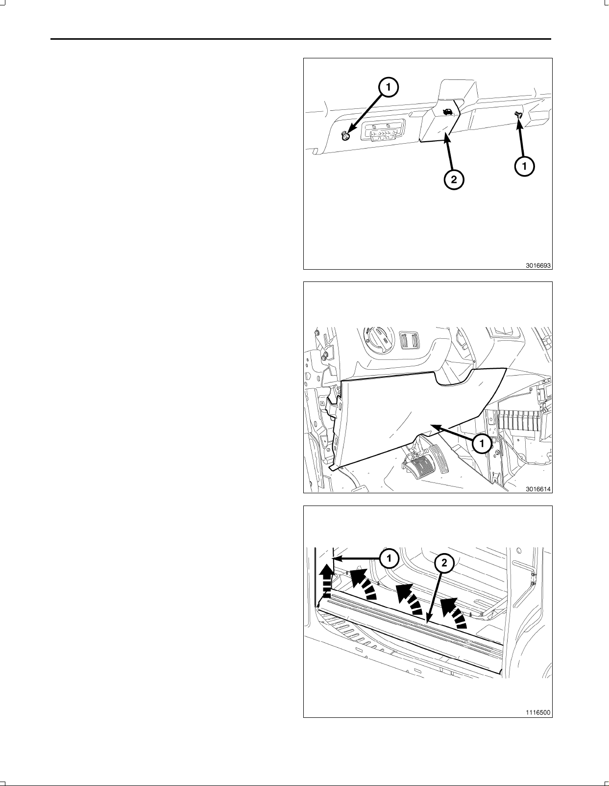
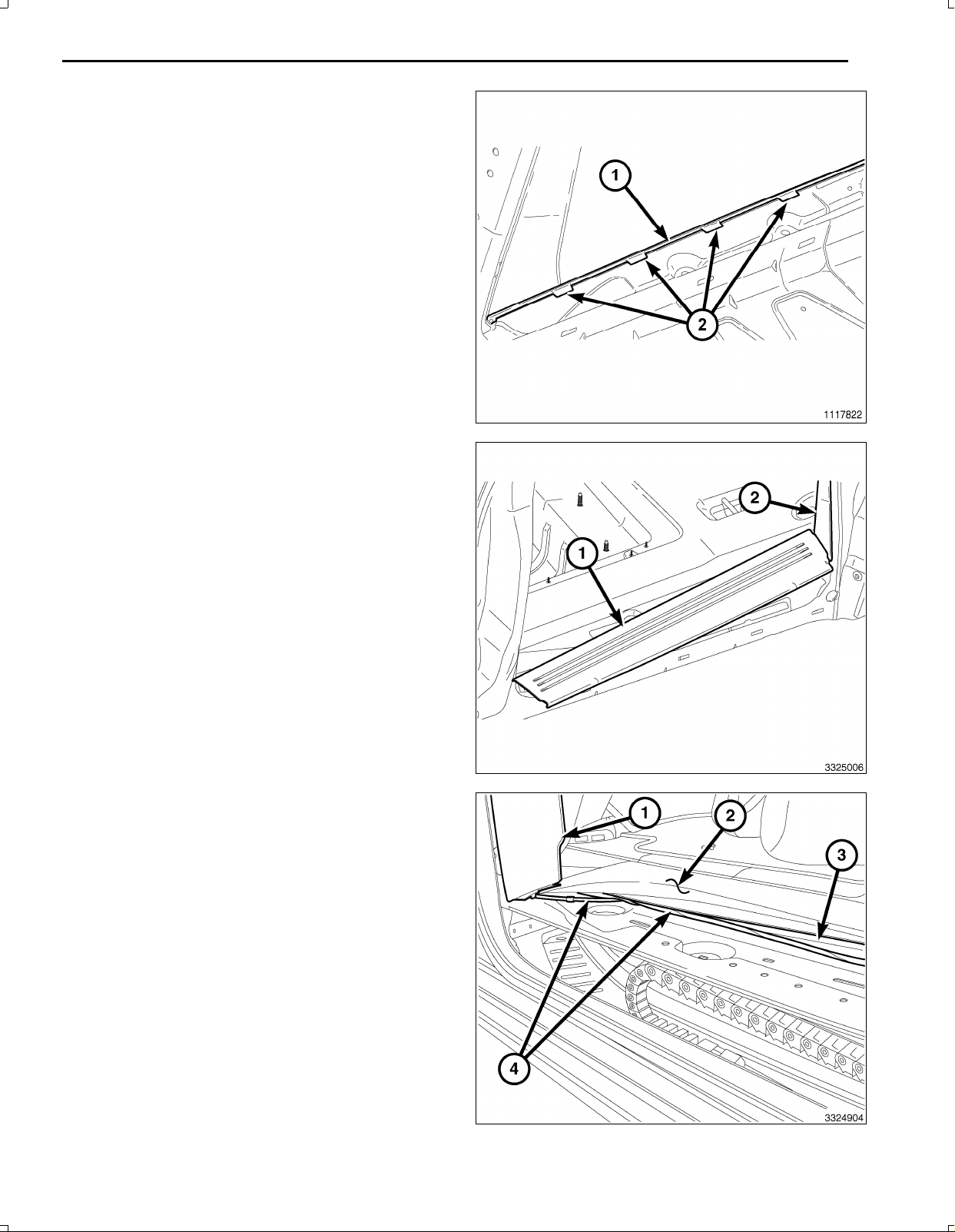
26.UsingTrimStickC4755gentlypryupontheliftgate
scuffplatetoreleasetheretainingclips(1).
27.Carefullydisengagethescuffplateendtabs(4)from
theleftandrightquartertrimpanels(5).
28.Removetheliftgatescuffplate(3)fromtheliftgate
opening.
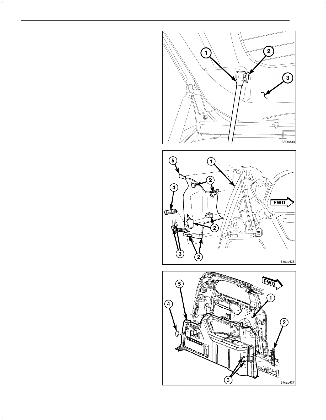
29.Removetherearheadertrimscrewcovers(3)andre
tainingscrews.
NOTE:Whileremovingrearheadertrim(2),carefully
routetheshoulderharness(1)fromtherearheader
trim(2).
30.UsingTrimStickC4755gentlyprydownontherear
headertrim(2)toreleasethesnapretainersandre
movetherearheadertrim(2).
31.UsingTrimStickC4755disengagethefrontandrear
quartertrimbolsterretainingclips(1).
32.Carefullydisengagethequartertrimbolsterupperre
tainingtabs(2)byliftingthebottomedgeofthebolster.
33.Continuepullingthequartertrimbolsterawayfromthe
quartertrimpaneltodisengagethequartertrimbolster
locatingtabs(4).
34.Slidetherearseatbelt(3)outoftheslotinthequarter
trimbolster.
35.Removethequartertrimbolster(5).
Jun30,2011K6861197

9
NOTE:Donotremovetheretainer(2).Whenprying,
theretainer(2)will"snap"totheunlockedposition.
36.Ifequipped,usinganappropriateflatbladedtool,pry
theplasticretainer(2)uptoreleasethelockingmech
anismfromtheheadofthepowerliftgatelinkrod(1).
37.Removethelinkrod(1)endfromtheliftgatebygently
pullingthelinkrod(1)awayfromtheliftgate.
38.UsingTrimStickC4755disengagetheupperDpillar
trimretainingclips(2).
39.CarefullydisengagetheupperDpillartrimendtab(5)
fromtherearheadertrimplate.
40.DisconnectthepowerliftgateDPillarswitchandthird
rowpowerfoldingseatswitchelectricalconnectors(3)
(ifequipped).
41.RemovetheupperDpillartrimfromtheliftgateopen
ing.
42.Removethesixquartertrimretainingscrews.
43.Pullquartertrimpanel(5)frominnerquarterpanel(1)
enoughtoroutethebackupcamerawiringharness
withthevehiclebodyharness.
Jun30,2011K6861197

10
44.UsingTrimStickC4755disengagetheretainingclips
thatsecuretheupperliftgatetrimpanel(3)tothelift
gate(1)andremovetheuppertrimpaneltogainac
cesstothelowertrimpanel(2).
45.Removethefourretainingscrews(1)fromthelower
liftgatetrimpanel.
46.UsingTrimStickC4755disengagetheretainingclips
thatsecurethelowerliftgatetrimpanel(1)tothelift
gate(2).
47.Disconnectthewireconnectorfromtheliftgatelamp
andremovethelowertrimpanel(1).
Jun30,2011K6861197

11
48.Disconnectthepowerlockinglatchcable(2)fromthe
exteriorliftgatehandleandremovethecablefromthe
handle.
49.Disconnectthewireharnessconnector(3)fromthe
exteriorliftgatehandle.
50.Removethetwobolts(4)thatsecuretheexteriorlift
gatehandletotheliftgate.
51.Removethetwobolts(1)thatsecurethebezeltothe
liftgate.
52.Removethepinchsensorretainingscrew(4)nearthe
cover(3)onbothsidesoftheliftgate(2).
53.Removethepinchsensorcoverpushinretainer(1)
onbothsidesoftheliftgate(2).
54.Openthepinchsensorcover(2)onbothsidesofthe
liftgate.
55.Pulltheendofthepinchsensor(3)downenoughto
accesstheexteriorbodypanelnut(1)underthesen
soronbothsidesoftheliftgate.
56.Removetheexteriorbodypanelnuts(1)onbothsides
oftheliftgate.
Jun30,2011K6861197

12
57.Removecenterbezelpanel(1)withlicenselampcar
rier.
NOTE:Whileremovingthecarrierinthenextsteps,
usingasuitablepryingtool(1)todisengagethetabs
(3)fromthecarrieropening(2)beforeseparatingto
preventthetabsfrombeingbroken.
58.Placethebezelonabench.
59.Removetworetainingscrews(1).
60.Separateclips(2)fromcarrierusingprocedureshown
above.
Jun30,2011K6861197

13
61.Turntheconnectors(1,3)andremovethemfromthe
licenseplatelamps(2).
62.Pressthetaboneachlampandremovefromthecar
rier.
63.Payattentiontotheroutingofthelicenseplatelamps
wiring(4)andremovethewiringfromthecarrier.
NOTE:Theconnector(1)fromthebackupcamera
wiringharness(2)willnotbeusedforthelicense
platelamps.Theexistingconnectormustbeused,
andtheconnector(1)fromthebackupcamerawiring
harness(2)mustbesecuredoutoftheway.
64.Installthelicenseplatelamps(2)tothenewcarrier
whichhasthebackupcamerainstalled.
65.Insertthelampconnectors(1,3)tothelampsandturn
tosecurethem.
66.Routethelicenseplatelampswiring(4)thesameway
asitwasremovedfromtheoldcarrier.
Jun30,2011K6861197

14
67.Snapthenewcarrierontothetabs(2)onthebezel.
68.Installandtightenthetwomountingscrews(1)tose
curethecarriertothebezel.
69.Installthecenterbezel(1)andsnapitintoplaceon
theliftgate.
70.Disconnectthe12Vignitionpowersourceelectrical
connector(1)frontthefrontstoragebincover.
Jun30,2011K6861197

15
71.Preparetocrimp/splicethebackupcamerapowerwire
(PK/OR)tothe(DB/PK)ofthe12Vignitionpowerout
letwiringharnessconnectorasfollows:
a.Cutthe12VignitionpoweroutletDB/PKwire.
b.Remove13mm(0.5in.)ofinsulationfromeach
wirethatneedstobespliced.
c.Placeapieceofadhesivelinedheatshrinktubing
(2)ononesideofthewire.Makesurethetubing
willbelongenoughtocoverandsealtheentire
repairarea.
d.Placethestrandsofwireoverlappingeachother
insideofthespliceclip(1).
72.Usingcrimpingtool(1),Mopar®p/n05019912AAor
equivalent,crimpthespliceclipandwirestogether.
Jun30,2011K6861197

16
CAUTION:Donotuseacidcoresolder.
73.Usingasoldertool(3),soldertheconnection(2)to
getherwithrosincoresolder(1).
74.Centertheheatshrinktubing(2)overthesolderjoint
andheatusingaheatgun.Heatthejointuntilthetub
ingistightlysealedandsealant(1)comesoutofboth
endsofthetubing.
75.Crimp/splicethebackupcameragroundwire(BK)to
theground(BK)ofthe12Vignitionpoweroutletwiring
harnessconnectorasabove.
Jun30,2011K6861197

17
NOTE:Theremayalreadybea22pinconnectortothe
radio.Usetheexistingoneanddiscardtheonesup
pliedinthekit.
76.Backouttheconnectorwirelockingtabfromtheradio
harnessconnector.
77.Insertthecameraharnesswiresintotheradioharness
connectorasfollows:
a.Signalwire(DG/BR)cavity3
b.Returnwire(DG/OR)cavity4
c.Shieldwire(DG/WT)cavity5
78.Positiontheradiototheinstrumentpanel.
79.ConnecttheAM/FMantenna(2).
80.Connecttheelectricalconnector(1).
81.Connectthesatellite/navigationantenna(3).
82.Ifequipped,connecttheUSBconnectors(4).
83.Installtheradio(2)mountingfasteners(1).
Jun30,2011K6861197

18
84.Positionthecenterbezel(1)overtheinstrumentpanel
andpressfirmlyandevenlyaroundtheperimeterof
thebezeltoseattheretainingclips.
NOTE:RoutingundertheI/Pshouldbeabovethe
brakepedalsledandsecuredtoeliminatepossible
interferencewithallpedalmovement.Routing
underthekickpanelshouldbesecuredtoeliminate
possibleinterferencewithallpedalmovement.
85.Routethebackupcamerawireharnessfromunderthe
LHsideoftheI/P(abovethebrakepedalsled)behind
theLFkickpanelandsecuretothevehicleharness
withtiestraps.
86.Routethebackupcamerawireharness(4)withthe
vehiclewiringharness(2)undertheedgeofthecarpet
(1)belowtheLFdoorscuffplateandbelowtheBpillar
lowertrim(3).Attachtothevehiclewiringharness(2)
withtiestrapswherenecessary.
87.Routethebackupcamerawireharness(4)underthe
edgeofthecarpet(1)belowtheslidingdoorscuffplate
andaroundtheedgeofthesecondrowseat(3)tobe
routedunderthequartertrimpanel.Attachtothevehi
clewiringharness(2)withtiestrapswherenecessary.
Jun30,2011K6861197

19
88.Routethebackupcamerawireharness(1)withthe
bodywiringharness(2)alongthequarterpanel.At
tachtothevehiclewiringharness(2)withtiestraps
wherenecessary.
89.Routethebackupcamerawireharness(2)withthe
bodywiringharness(1)uptheDpillar.Attachtothe
vehiclewiringharness(1)withtiestrapswherenec
essary.
90.Routethebackupcamerawiringharness(1)through
thebodypassthroughabovetheheadlinerattherear
oftheroof.
Jun30,2011K6861197

20
91.Separatetheupperandlowergrommets(1,2)from
thebodyholes.
92.Routethecamerawiringharnessthroughbothgrom
mets.Oncetheharnessisthrough,seatthegrom
metsintheiroriginallocations.
93.Routetherearcameraharness(2)alongtheexisting
harnessandsecurewithtiestraps.
94.Installtheconnector(1)asshowninthenextsteps.
95.Backouttheconnectorterminallockingtabfromthe
backupcameraconnector.
96.Insertthebackupcameraharnesswiresintobackup
cameraconnectorasfollows:
a.12Vignitionpowerwire(PK/YL)cavity2
b.Signalreturnwire(DG/OR)cavity3
c.Signalwire(DG/BR)cavity4
d.Shieldwire(DG/WT)cavity7
e.Groundwire(BK)cavity8
Jun30,2011K6861197
Table of contents
Languages:
Other Mopar Automobile Electronic manuals