Bengtson BE2C User manual
BE2c367/8”
Copyright©2007‐11M.K.BengtsonAllRightsReservedRev07/11
BE2C 36 7/8” 1/12th Scale
R/CScaleModelInstructions
CONTACTINFORMATION
DesignedbyM.K.Bengtson
PrototypebyJohnO’Duffy
ManufacturedandDistributedby:
BengtsonCompany
www.aerodromerc.com

BE2c367/8”Page1
Copyright©2007‐11M.K.BengtsonAllRightsReservedRev07/11
BE2C367/8”1/12thScale
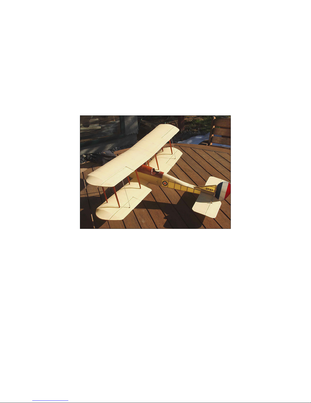
Thankyouforpurchasingthe1/12thScaleBE2Cfor
electricflight.
FinishedModel
ModelSpecifications
Morethan255lasercutparts
Scale: 1/12
Channels: R/E/A/T
Wheels:balsaandplywoodwithNeoprenefoamtires
Wingspan: 367/8ʺ
WingArea: 374.5sqin
Weight: ~25oz
PowerSystem:GWS300c
Prop: 10x7
AirfoilType: Flatbottomed;optionalundercamber
Cowl: N/A
Spinner: N/A
Decals: Availableonwebsite
Designer: M.K.Bengtson
Prototype: JohnO’Duffy
Preparation
Layoutthe2plansheetsandlasercutkitparts.
Studytheplansandidentifyallsuppliedparts,you
mayliketomarkthepartnumbersbesidethepartfor
lateridentification.Asyougo,prepareyour‘stick
shoppinglist’ofstocknotincluded.Thislistwillinclude
butisnotlimitedto,suchaswingspars,leadingedges,
1/8”squareforrearfusesection,andsome1/16”and1/32”
balsasheeting.
Plansandpartslaidout.
Duringconstruction,plansshouldbecoveredwith
somesortof‘planprotector’suchascommercially
availabletypes,or‘greaseproofpaper’orclingwrapor
eventheplasticbagthekitcamein.
Glueisuptoyou,somebuilderslikeCAglueswhich
certainlyspeedsconstructioningeneral,butensureyour
workareaiswellventilatedasmanypeoplehaveadverse
reactionstothepoisonousfumes.Epoxyglueshouldbe
usedforthefusefrontmainstructureforstrengthand
durability.‘White’woodglueisagoodalternativetoCA,
ittakeslongerwaitingforittosetbutgivesmoretimeto
preciselylocateparts,avoids‘stuckfingers’andis
generallyamorestressfreeexperience.
Tools.Notmuchmorethanasharpknifewithagood
supplyofreplacementbladesandsomesandpaperis
required.Veryhelpful,especiallywiththismodelis
havinganumberofset‐squares,straightedgesandrules
availablefortruinguppartsasconstructionproceeds.
Whenremovingpartsfromthesuppliedsheetsuse
careandaverysharpbladetocutthesmallbridges
holdingthepartintothesheetbeforeremovingit.Simply
pressingthepartoutofthesheetriskstearingorbreaking
it,especiallywithsomeofthefinerparts.
Thefuse,wings,tailsurfacesandundercarriage
sectionsareallconstructedseparatelyandbrought
togetherattheassemblystage.Itdoesnotmatterinwhich
orderthesesectionsareconstructedbutnormaladvise
wouldbetostartwiththetailplanesasthattendstobe
easiestandleadsintowingthenfuseconstruction.This
wouldbegoodadviseifyouarenotfamiliarwith
AerodromeRCkits.

BE2c367/8”Page2
Copyright©2007‐11M.K.BengtsonAllRightsReservedRev07/11
TailPlanes
VerticalFinandRudder
RemovepartsS1–S9fromthe1/8”sheet.Youwillalso
needsome1/16”x1/8”balsafromyourstickstock.After
coveringtheplanswithyourchosenprotectorlaythe
partsovertheplans.Whenyouarehappywithhowthe
finandrudderaretobeconstructed,startbypinningthe
twoverticalpieces(S3andS4)totheboard,thenwork
aroundtheruddergluingandpinningeachpieceto
completetheoutsideoftheframe.Fillinthethree
1/16”x1/8”piecesandS11tocompletetherudder.Finish
offtheverticalfinbygluingS1andS2toS3andaddthe
two1/16”x1/8”ribs.Makesureeverythingstaysflat.
Allowwhateverglueyouareusingtocompletelycure
andhardenbeforeremovingthecompletedpartsfromthe
plans.Don’tattachtheplycontrolhornuntilafter
covering.
HorizontalStab.andElevator
H5&H2arelongandsomewhatfragile,usecarewhen
removingthemfromtheirsheetsandwiththelightestof
sandingremoveanyremnantsofthelasercut‘tags’.
Usingastraightedgetokeepitdeadstraight,pinH5
totheplansinposition.GlueandpinH1,thenwith
anotherstraightedge,similarlyglueandlocateH2toH1.
AddthetwoH4sidepiecesandH3’stothecorners.Cut
andfitthe1/8”x1/16”ribs.
Tip:Cutthefirstrib,sandandfitneatlytothe
horizontalstabiliser.Cutalltherestfromthispattern
makingthemeversoslightlyoversize.Acoupleofstrokes
onsandpaperwillbesufficienttotunethesetolengthas
youfitthem.Donotdistortthestructurebytryingto
squeezeinaribthatisjusttoolong,acouplemorestrokes
onthesandpaperandit’llbeperfect.Ifyouover‐sandany
andit’stoolooseafit,putitasideandcutanother.The
shortonecanbeusedforanelevatorrib.
Horizontalstab.startandcomplete.
Whenalltheribsaregluedintothehorizontal
stabiliserremovethestraightedgeagainstH5.
Elevators.
PinthetwoE1totheplans,somethinspacermaterial
betweenH5andthetwoE1willmakethiseasy.Work
aroundtheoutsideontheelevatorstocompletethe
outline.Addtheribsandthetwocontrolhornanchorsto
completethissection.Donotaddthecontrolhorns
themselvesuntilaftercovering.
Wings
Thewingscanbebuiltwithorwithouttheoptional
undercamberwhichislasercutintotheribs.Itisnomore
difficulttohavethisoptionreally,theribsstillsitnicely
flatonthebuildingsurfaceevenafterremovingtheextra
material.Undercamberdoesrequirealittlemore
attentiontotheaileronservohatchareaandyou’llneedto
checkyourservo’sarethinenoughinthenarrowedwing.
Ifyoudowantundercamber,thelasercutlinesareeasy
tofinishwithasharp#11knifebladeandatouchof
sandpapertoremovethe‘bumps’.Don’toversand.Finish
eachrib’slowersurfaceasyouremoveitfromit’ssheet
andyouwon’tevenhavetosandtheundercamberonthe
completedwing.Otherthanalittlemorepreparationof
eachrib,andservorailfitting,wingassemblyisthesame
withorwithoutundercamber.Alsonotewithunder
camber,theply‘P’piecesthatmakethecarbanestrut
socketswillneedsomemoreattentionontheunder
surfaceoftheupperwingbeforecovering.

BE2c367/8”Page3
Copyright©2007‐11M.K.BengtsonAllRightsReservedRev07/11
UpperWings
Selectfourstraight¼”x1/8”bassorsprucesparsfrom
yourstock.Shapetheoutboardendsofthesparsasper
thedetailontheplans.
Foreachwing;
PinW1andW1ainposition.Cutsparstolengthand
fixtoplans.Glueandplacetheinboardoneofthetwo
R3’s,R5andthewingtipR6,checkallisflattothe
buildingsurface,straight,andtheribssquare.
Alsonotethatwiththeinboardribsoftheupperwings
thesparcutoutsarelargerthanthespartoallowlater
insertionoftheplydihedralbracesinfrontofthespar.
Whengluingtheseribstothespars,ensurethesparis
againsttherearofthecutoutintheribs,leavingroom
(1/16”)fortheplybrace.
‘X’pinningthesparswillholdthemdownanduprightwhile
fittingtheribs.
Positionthelowerinboardplytrailingedge.
LeavingribR2tilllast,glueintheremainingribsand
halfribstothewing.GlueinribR2usingtheRFGguide
supplied,thiswillhelpachievethecorrectdihedralangle
whenthetopwingsarejoined.ThetopofribR2leans
awaytowardsthewingtip.
Addtheuppersurfaceplytrailingedges,andapplya
littleweightsothetrailingedgestaysflatandstraight.
Theplytailingedgepiecesrequirenoextratapering,the
narrowedribsaredesignedtolettheedgesoftheplyto
justmeetalongtheirbackedges.
Cuttolengththe¼”x¼”leadingedgefromyourstick
stock.Carefullyremoving/sandingoffonepointofthe
squaresectionforitslength,asindicatedbytheplans,test
andthenfittheleadingedgetothemouthsoftheribs,
glueinplace.Installtheply‘P’pieceseithersideofthe
1/8”ribstoformtheIPstrutsockets.FittheTEpiecesto
finishthewingattheaileronmount.(NottheLEpieces,
theybelongtotheaileron!)
Ailerons
Preparethe6aribpiecesandtheone1/8”6bpiece.Pin
W2andLEinpositionleavingasmallgapattherootend
foraileronclearance.Usingapinwillhelpkeepthegap.
Layaplytrailingedge(upperwing,lower=plywith
horncutout)ontheplanandfit6battherootendanda
6aatthetipend.
Gluetherestofthe6aribsinpositionandaplytrailing
edgeontop.Ensuretheplypiecesaresittingflatinthe
ribsandapplysomeweighttokeepitallflatastheglue
hardens.(Ontheupperwingsthistopsurfaceplypiece
hasnocutout)
TheWingWorks.Wingsatvariousstages.
LowerWings
Proceedasforupperwingsforthebulkofthe
construction.Lowerwingsparscanbeleft1/8”overlong
attherootends;therearecutoutsinthefusesidesto
receivethesesparends.
Withtheaileronsensurethecontrolhorncutoutsinthe
plytrailingedgesareontheuppersurfacethistime.The
BeWarned!Controlhorncutoutsinthe
plyailerontrailingedgesneedparticular
attention.Ontheupperwingthecutouts
areonthelowersurface,onthelowerwing
theyareontheuppersurface.Alsomake
surethecutoutisoveritspositiononthe
plans.

BE2c367/8”Page4
Copyright©2007‐11M.K.BengtsonAllRightsReservedRev07/11
lowerwingaileronsalsohavethebalsacontrolhorn
mountlabelled‘3’;thisisflushwiththelowersurfaceof
theaileron.
PartsW3andW4needshapingtosuit,W3being
taperedtosuitandW4trimmedtothewingcord
(thickness)beforebeingfitted.Sheettherootwingpanel
(uppersurfaceonly)with1/32”balsaasindicatedonthe
plan.Epoxyinthe1/8”dowelsleaving1/8”protruding
whichwilllocateintheholesprovidedinthefusesides.
Fourstrongwings
AileronServohatch/mounting
Ifyouarenotusingtheundercamberoption,gluethe
¼”x¼”servorailsinpositionbetweentheribsoverthe
plans.Ifyouwanttheplycoverrecessed,putsome1/32”
packingbetweentheplanandtherailasyoupositionit.
(Don’tglueinthepacking!)Alsoifyouarerecessingthe
cover,addanotherpieceof1/8”balsatothefrontservo
railflushwiththewingribs,to‘finishthebox’andattach
thecoveringmaterialto.
Servohatch,undercamberandrecessed.
Ifyouareusingundercamber,waittillthelower
wingsarecompletelydry.Markthepositionsoftheservo
railsonthewingribsfromtheplansthenliftthewings.
Testtherailsinthemarkedpositionsflushwiththe
sandedlowersurfaceofthewingribsbyusingtheply
hatchtocheck.Torecess,pushinthehatchsoit’sflush
withtheribs.Tacktherailsinplace,checkwiththeply
hatchallisniceandflush,removehatchandsecurethe
rails.Alsoifyouarerecessingthecover,addanother
pieceof1/8”balsatothefrontservorailflushwiththe
wingribs,to‘finishthebox’andattachthecovering
materialto.
Theservoisattachedtothehatchbygluingitdirectly
orscrewingittoblocksgluedtothehatch.Hereblocksare
gluedtothehatchtopositiontheservoandsiliconwillbe
usedtoglueintheservosothatitcouldberecycled.Some
builderswraptheservointapethengluethetapedservo
inplace.Latercuttingthetapewillreleasetheservo.
Joiningtheupperwings
Assemblethecentresectionoftheupperwing,joining
the3ribstotheplytrailingedgepiecesandasectionof
preparedleadingedge.Installapieceof1/8”x¼”spar
materialtothebackofthespacesintheribs.Prepare1”x
6”blockswhichwillgounderthewingtipsastheyare
assembled,toestablishthedihedralangleofthewings.
Trailfitthefourplydihedralbracestotheupper
wings.Asmallfilewillhelprelievingtheslotsinthewing
ribsiftheyaretootight.Thebracesmayneedtrimmingso
theymeetatthecentrelinewithoutinterference,check
thisovertheplan.Whenthefitisgood,epoxythemin
place.Locatethewingsovertheirpositionontheplan
withthe1”blocksunderthetips,applyepoxytothe
assembledcentresectionribsand‘spar’andslideitdown
betweenthewingribsslottingtheplydihedralbracesinto
position.Checkthatthecentresectionissittingflatonthe
worksurface,thewingtipdihedralblocksareincorrect
positionandthatthewingsatthatpointaresittingflaton
theblocks.Checkyouhaveanicestraightlinealongthe
leadingedge.
Upperwingcentresection.

BE2c367/8”Page5
Copyright©2007‐11M.K.BengtsonAllRightsReservedRev07/11
FuselageConstruction
Thefuselageisbuiltintwosections,afronthalfanda
rearhalfwhicharethenjoinedovertheplan.This
simplifiesconstructionandhelpsensureastraight
fuselage.
Cowl
GluepartsC1andC2together.The‘top’(flatter)
surfacesandsidesareflush,thelower(morerounded)
surfacesaresteppedforlatersandingtotheprofileonthe
plans.
FrontSection
Startbypinningone1/8”balsafusesidetotheside
viewplanandepoxyFCBandRCBcarbanestrutsinto
theirslotsinthefuseside.NoteFCBandRCBare
different.Ensureeverythingispreciselyovertheplanand
thestructurestaysflatwhilethegluesets.Wing
alignmentwilllaterdependontheaccuracyofthis
assembly.
EpoxyFCBandRCBintofuseside.
Whenthegluehascompletelyhardenedonthefirst
side,eitherremoveitandrepeatforthesecondside,or
buildthesecondsideoverthefirstwithapieceofcling
wrapinbetweensothetwodon’tgluetogether.Either
waytheintentistoachieve2identicalsideswiththe
carbanestrutsalignedandvertical.Thereisnoleftorright
sidetoworryaboutheretheyarethesame.
WhilethesecondsidesetslocatepartsF2,F6,F1Dand
cutthe1/8”x1/4”crossbracesinpreparationforjoining
thefusesides.CleaningouttheU/ClacingholesinF1D
(andF1C)witha1/16”drillwillbeeasiernowthanlater.
Formingthebasisofthefrontfusesectionbeginswith
pinningF1Dtotheplanviewoverit’slocation(note
orientation–lacingholestotherear).Usingepoxy,attach
thetwofusesideswithF2andF6between,toF1Dand
thenthecrossbracestothetop.Taketimeatthisstage,
andusestraightedgesandsquarestoensureeverythingis
deadstraightandsquareandthatthecarbanestrutsand
fusesidesareverticaltothebuildingsurface.
Mainfusepartssetting.(Smallbagofshotweighingthings
down)
Therestofthefuseformersetccanbegluedinafter
thetruenessofthebasicstructurehasbeenachieved.
Nowtheplansideviewhasbeenvacatedconstruction
ofthetaillatticecouldbeginwhiletheepoxysetsinthe
fronthalf.SeeTailSectionbelow.
Whenthebasicfrontstructurehascompletelyset,
continueaddingtheremainingformersF1,F3,F4andF1C
(lacingholestothefront).CheckF1isvertical,withthe
fuseonits‘flat’(ieF1Disflattothebuildingsurface).
Checkcarbanestrutsremaintruewhenattachingthefour
F3formerseithersideofthesestruts.NotetheformersF3
&F4arenarrowerthantheoverallwidthofthefusesides
toallowforthelater1/16”sheetingoftheupperhalf,
ensuretheyareevenlyspacedeitherside.
Installthemotormount3/8”squarestock,usethe
planstohelpestablishthe2‐3degreerightanddown
thrustangles.Completethisstagebygluinginthefour
servomountingrailsasindicatedontheplans.Allowglue
tosetcompletely.
Nextthefusesidesneedtobescoredandcracked
behindF6totaperthesidestothenarrowerF7.
AfterscoringtheinsidesofthesidesjustbehindF6,
locatethefuseovertheplansandbend/crackthesides
behindF6inwardsevenlytoconformtothewidthofF7
keepingitallalignedandpositionedwiththeplans.Glue
andtemporarilytapeF7tothesides.Gluereinforcesyour

BE2c367/8”Page6
Copyright©2007‐11M.K.BengtsonAllRightsReservedRev07/11
score/cracklines,ensureeverythingconformstotheplan
andallowtoset.
FusecrackedforF7
Tohelpavoidhangerrashlateronafewothertasks
canbecompletedatthisstage.Epoxythetwo1/8”brass
bearings(cutfrom1/8”brasstube)intotheirholesinthe
fusesidesjustforwardofF6.Usealengthon3/32”rodor
tubethroughbothbearingstokeepthemalignedasthe
epoxysets.Thebearingsshouldbeflushtotheoutside
andcaneachbe3/8”longsoastogive¼”ontheinside
forglueattachment.Ensureyour‘alignmentrod’through
thebearingsdoesnotgetgluedinplace!
Sheettheundersidefrontofthefuselagewith1/32”
balsa.Usecardtomakeapatternoftheshaperequired,
trimminguntilit’saperfectfitapartfromthefront,which
canbeleftover‐lengthandtrimmedlater.Cutapieceof
1/32”balsasheettothispatternandsoakunderawater
soakedpapertowelfor20‐30min.Thatshouldmakeit
flexibleenoughtotakethecurvedshape.Glueandtape
thesheetinposition.
(Tip:Ifyouarenotexperiencedinsheetingcurveswithbalsa,
thisisafairlysimplecurvetostartwith.Usecardtocreatea
pattern,you’llfind,balsabendsawayfromthewetside,balsa
expandsasitsoaksandshrinksbackasitdries.Bepreparedto
havemorethanone‘go’atyourfirstsheetingattempts,ifit’s
wrong,orthebalsacracksthrowitaway,startagain,it’lltake
onlyaslongasittakestogetright.)
Lastlythemotorcanbefittedtothemountstickwitha
screwortwo,screwsskewedtothefrontsothatthey
couldberemovedthroughthefrontforservicing.The
motorcannowbetakenoutagainsoitdoesnotgetfilled
withbalsadustlater.
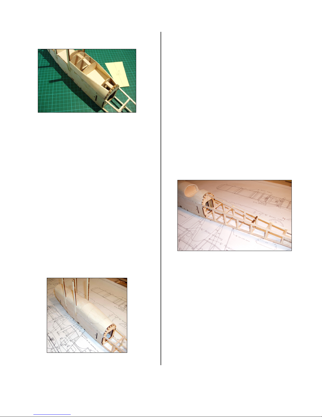
Frontandrearsectionsreadytojoin.The‘bar’throughthefuse
iskeepingthebearingsaligned.
Thefrontsectionisnowreadytojointotherear
sectionwhenthatiscomplete.
TailSectionofFuselage
LocatepartsFS1andFS2.Pinthe1/8”square
longeronstotheplanandglueinthecrosspieces,andFS1
andFS2atthetail.Apieceof1/8”squarestockhasbeen
usedinthephotobetweenFS1andFS2tomaintainthe
spacingrequiredforthelaterinsertionofthehorizontal
stabiliser.Makesureitdoesnotgetgluedin!
Fusetailconstructionstarts.
Whenthefirstsidehashardenedremoveitfromthe
plan,turnitover,coverwithalayerofclingwrapand
buildthesecondsideoverthefirstsothetwoare
identical.

BE2c367/8”Page7
Copyright©2007‐11M.K.BengtsonAllRightsReservedRev07/11
Thenthereweretwo
Jointhetwosidesovertheplans.
Notethesideshaveatopandbottomnow,established
byFS1&FS2.
Dothebottomsurfacefirst,pinSF7inpositiononthe
plan,buttthetwosidesuptoSF7keepingthemvertical
andlocateSF5andthesmall1/8”sq.crossbrace(between
SF7andSF5),betweenthetwosides,addthe1/8”sq.to
thefrontofSF5.Addtheremainingfivecrosspieces.Keep
everythingflatandthesidesvertical,allowtodry.
Gluingthecrossbracesbottomsurfaceofthetail
Thetailpiececannowbeturnedoverontheplanand
thetopsurfacedonesimilarlyusingFS6thistime.Note
‘leaveout’twoofthecrossbraces,theonesatlocations
F10andF11arekitsuppliedpartsandwillbeattached
later.
FinishoffaroundthetailareawithpartsSF3andSF4
oneachside.(Apieceof1/8”scrapsheetwrappedincling
wrapstandinginforthehorizontalstabiliserwillhelp
keepeverythingalignedandinposition.)TheendsofSF3
andSF4willneedlightsandingtoneatlymeetatthepoint
andsides.MakingSF3andSF4slightlyproudwillallow
sandingofthisareatotheprofileformedbythetwoSF7
Tailsectionreadytojointofront.
Joiningfrontandtailfusesections.
Thisimportantstepisrelativelyeasy,inthattheunder,
rearsection/planeofthefrontfuseandthebottomsurface
ofthetailsectionareaflatplaneallowingbothtobeflatto
thebuildingsurfaceduringconstruction.
Usestraightedgesorblocksfixedtotheplanseither
sideoftheforwardfusesectiontokeepitaligned.Rock
thefusebackbetweenit’sguidessothatitsitsflatonthe
backfacetoftheunderfuseshape.Usesomeweightto
holdthefuseinthis‘noseup’attitude.Nowslidethetail
section(dry,noglueyet)intopositionlocatingthe4
longeronendsintotheirsocketsinthefrontfuse.The
bottomsurfaceofthetailsectionisflattothebuilding
surfacejustliketherearoftheforwardsection.Check
everythingovertheplansforlengthandalignmentand
thatthe‘point’ofthefusetailisexactlyoverit’sposition
ontheplans.Trimlongeronsiftheyaretoolong.When
youarehappyallisasitshouldbe,slidethetailoutagain,
applygluetothesocketsinthefusefrontandslidethetail
backintoposition,checkthepointofthetailagain,and
allowtoset.Standbackandadmireyourperfectlystraight
fuselage.
Finishoffanyremainingformersandthecockpitfloors
inpreparationforsheetingthetopofthefuse.
Uppersheetingstarts
Cutsomelengthsof1/16”balsafortheuppersidesof
thefuse,wideenoughtofillbetweenthe1/8”lowerfuse
sideandthe‘chine’lineoftheupperformers.Sandor
planeanangleonthetopedgeofthesetocontinuethe
lineoftheformertops,thiswillhelpwithfittingthetop
sheet.Cutthesidestocorrectlengthandfitthe3pieces
eithersidetothefuse.Theaftsideswillrequiresome
BE2c367/8”Page8
Copyright©2007‐11M.K.BengtsonAllRightsReservedRev07/11
bendingtoconformtotheroundingshapeoftheformers,
soakingwithwetpapertowelfor20‐30minswillhelp.
Rear‘sides’curvedtofollowformers,cardtemplatefortopsheet
readytogo.
Thetopsheetingforthismodelwasdoneintwo
pieces,forwardandaftofthelastF4former.Usecardto
maketemplatesforcuttingthe1/16”balsasheeting.Start
withapieceabout1“wideandlongerthanyouneed.
Benditintopositionbetweenthecarbanestruts,markthe
positionofthestruts,removeandcutstrutnotches.Test
fitthenotchesandmarkthelengthrequired,leavingsome
overatthefront.Makethereartemplatebytaperingto
thewidthrequiredatF7.Whenthetemplatesare
complete,layover1/16”balsasheetandcarefullycutto
shape.Onceagainsoakingthebalsashapesunderawet
papertowelwillmakeitsufficientlyflexible.Layingthe
balsaoverasuitableroundshape(e.g.aspraypaintcan)
asit’ssoakingwiththepapertowelontopwillhelpeven
more.Preparetheformertopsandfusesideswithglue
andinstallthetopsheetsholdingitalldownwithplenty
ofmaskingtape.Thetopsheetshouldbeoverhangingthe
sidesbya1/16”orsooneithersideandmorearoundthe
aftcockpit.Sandsmoothwhenthegluehascompletely
dried.
Topsheetingdoneandcockpitsmarked
Nextmarkthepositionandshapeforthecockpitcut
outs.Atechniqueforgettingsymmetricalshapesisto
startwithcard,cutarectanglebiggerthanyouneed.Lay
overthefuseandmarkthelengthyouneedtohave
crosswaystogetthelowestpointsofthecutoutsinthe
correctpositiononthefuseside.Thewidthofthe
rectangleisthefore/aftdimensionofthecut‐outmeasured
fromtheplans.Foldthecardrectangleinhalfsuchthat
thefoldisthecentrelineofthefuse.Transferthecockpit
shapeshownonthesideviewplantoonesideofyour
template.Cutthetemplate,bothsidesatonce,tothis
shape.Openoutthetemplateandalignthefoldlinewith
thecentrelineofthefuse,positioningforeandaftasper
plan.Markaroundtheoutsideofthetemplatewithpencil.
Putanewbladeinyourknifeandwithlightpressure
followthepencilledline.Twoorthreepasseswiththe
bladeshouldseeaneatcutout.Toomuchpressurewill
‘break’thebalsa,toolittleandit’lljusttakeanotherpass,
butyou’llgetaneatcut.
1st stringer and F11
Stringerreardecking
FitandgluepieceF11inpositionbetweentheupper
longerons.Cutthe1/8”x1/16”centrestringertolength,
glueeitherendtoF11andF7.Usingthisasyourguide
assembletheotherupperdeckformersbetweenF11and
F7ensuringtheformersarevertical.Installtherestof1/8”
x1/16”stringers,apairoftweezerswillhelppositioning
theoutboardstringswhichrequiremoretwistbetween
formsF10andF11.Thecutoutsintheformertopsthat
separatethestringersareextremelyfragile,especiallyin
partsF10andF11,useasmuchcareasyoucan,whenyou
breakoffapiece(oh!youwill☺),reattachwithCAas
youassemblethestringertomaintainthespacingbetween
thestringers.

BE2c367/8”Page9
Copyright©2007‐11M.K.BengtsonAllRightsReservedRev07/11
Upperdeckstringers.
Undercarriage
Usingtheplansasaguidecutandshape1/16”music
wiretoformthetwoUCsupports.Gluetogethertheply
UCsidesandsetaside,thesecanbesmoothed/sanded
afterbondingtothewirelegs.Makeyourselfa‘jig’toaid
assembly,asshowninthephoto.
Bindtheendsofthe1/16”musicwirewiththincopper
wireorKevlarthread,usingtheplysidestoguidethe
shape.The‘front’legsshouldbeverticaltothejig,usea
squaretocheck.Somere‐bendingandtuningwill
probablyberequiredtogettheshapeevenand
symmetricaloverall.Whenallisasitshouldbe,bindand
CA/Epoxytheplysidesinplacesecuringthemtothe
1/16”musicwire.
Assemblewheelsbysandwichingthe¼”balsamiddle
piecebetweenthe1/32”plysides.Useapieceof3/32”
tubetoalign/centretheparts,thenremovethetubeand
‘squash’thewheelundersomeweighttomakesureit’s
flatasthegluesets.Whenthisisdrycuttwowheel
bearingsabout5/8”longfrom3/32”brasstube.Usingthe
1/8”plyhubsandawheelbearing,completeeachwheel
usingepoxy,makingsurenoepoxygetsintothebearing.
Beforegluesets,spinthewheelon1/16”musicwireaxel
andrealignbearing/hubsasrequiredtoensurethewheel
spinsstraight.
Toformthetyresmassageonesideoftheneopreneso
itstartstocurl,continueanditwillformacircle,near
enoughanyway.UseCAtogluetheendstogether,butbe
carefulasCAandneopreneisaVERYstickycombination
andiffingersgetinvolveditcangetverymessy.Placethe
neopreneflatonaprotectedpartofyourworksurface.
UseonesmalldropofCAononeend,bringtheotherend
aroundtomatewiththegluedendtryingtoachievea
smoothjoin,you’llonlygetonechance.Whenthetyreis
formedrollitontothewheelandwithatinydroporthree
ofCAsecuretotherim.Onceagainbecarefulwiththe
CA,ifyoustickafingerorthumbtothetyrematerial
you’lllikelytearachunkoutoftheneoprenetryingto
releaseit.
UCandwheels
Thecardconesrequiredtodressthewheelsshouldbe
cutfromcardtothesizeshowontheplans.Scorelines
deeplyintothecutcirclewithapenandcutoutonepie
shapedsection.Foldtheshapesateachscorelinetomake
these‘spokes’moreobvious.Drawtheendstogether
formingaconeandtapeinsidetomaintaintheshape.
GluetheinsideconetoeachwheelandinstalltotheUC
structure.Ensureitspinsfreely,someshortlengthsof
3/32”tubemayberequiredtospacethewheelawayfrom
theUCstructure.Thewheelcanberetainedontheaxelby
asmallwasherandCA/binding.Trimaxeltolengthand
glueoutercardconetowheeltocomplete.
BE2c367/8”Page10
Copyright©2007‐11M.K.BengtsonAllRightsReservedRev07/11
Tailskid
Bendapieceof1/16”musicwiretotheshapeshown
ontheplans.Cuttwopiecesof1/16”balsa3/16”x1‐5/8”
andtwopieces1/16”x1/16”x1‐5/8”.The1/16”kitsheet
thatheldtheaileronribsisagooddonorforthesebalsa
parts.Asshownontheplansforma‘box’aroundthe
1/16”musicwirewiththebalsastrips.Fittheskidtothe
wirewithasmallwashereitherside.Ensuretheskidis
goingtositcorrectly,youmayhaveto‘fix’theinside
washertothemounttogeteverythingtositstraight.
Whenyouarehappyinstalltheoutsidewasherandbind
theendoftheaxel.Trimaxeltosuit.Makesuretheskid
stillmovesontheaxel.Arrangeamountnearthetopof
thestructurefortheelastic‘shockabsorber’shownonthe
plans.Thisshockabsorbercouldbethindressmakers
elasticorevenasuitablysizedrubberband.
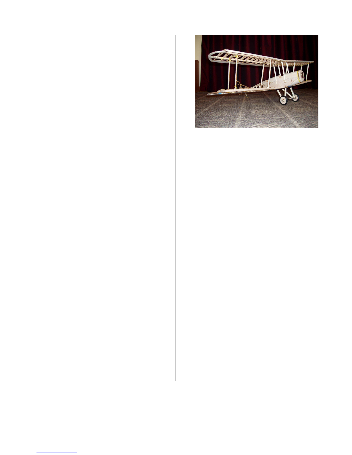
TrailAssembly
Usingnoglue!Thisisadrytestassemblyrunto
ensureallmajorcomponentsfitwell.
Placethetopwingupsidedownonyourworksurface,
supportunderthemidsectionwiththe1”dihedralblocks
weusedtosetthetipssothatthewinghassomesupport.
Fitthefusetothetopwingbyinsertingthecarbane
strutsintotheirsocketsinthetopwing,makesurethey
seatallthewaydown.Usesomelighttapetoholdin
place.Placesomesupportunderthefusetailtolevel
thingsup.Checkthedistancebetweensomefixedpoint
oneachwing,saytherootendoftheaileronspace(or
wherethelastwingtipribmeetsTE)andthepointofthe
aftendofthefuse.Thisshouldbethesameonbothsides
andtellshowwellyouputthecarbanestrutsandfuse
sidestogether.Ifthere’sanydiscrepancyitwillneed
adjustmentduringfinalassembly.Withtheassemblystill
upsidedown,installfourIPstruts(notethereareForward
andAftIPstrutsFIPandRIP)inonesideoftheupper
wing.Positionlowerwing,locatingIPstrutsbetweenthe
wings,andwingdowelsandsparendsintothefusecut
outs.Repeatfortheotherlowerwing.Usetapetohold
everythinginplace.Tapetheundercarriageinplace.Turn
theassemblyoverandslidethehorizontalstabiliserinto
place.LocatetheverticalfinintoitsslotinFS6.Installthe
tailskidassembly.There…looksgreat!
FLYING
• ThemodelshouldROGongrass,pavementor
hardsurfaces.
• Letthemodelgainaltitudeslowlyofftherunway.
• Applyingtoomuchupelevatoratslowspeeds
risksastall.
• Makeyourturnsgentlyastightturnsrisktip
stallinginanymodel.
• Don’texpecttheelevatortomakethemodel
climb.
• Thinkoftheelevatorasadevicetochangethe
attitudeofthemodel.
• Thewingandairspeedultimatelymakethe
modelclimb.
• Oftendownelevatorappliedatstallingcanavoid
amajorcrash.
Themostimportantdetailsforproperflight
operations:
• Correct CG location.
• Straightnon‐warpedwings.
CONTACTINFORMATION
Distributedby:
BengtsonCompany
WebSite:www.aerodromerc.com
Table of contents
Popular Aircraft manuals by other brands

Piper
Piper SARATOGA II HP PA-32R-301 Pilot operating handbook

Textron
Textron Cessna 172R Information manual

czech sport aircraft
czech sport aircraft SportCruiser Operating handbook

AIR TRACTOR
AIR TRACTOR AT-402A quick start guide

Zlin Aircraft
Zlin Aircraft Z 242 L Airplane Flight Manual

UP
UP K2 Owners manual and service manual


