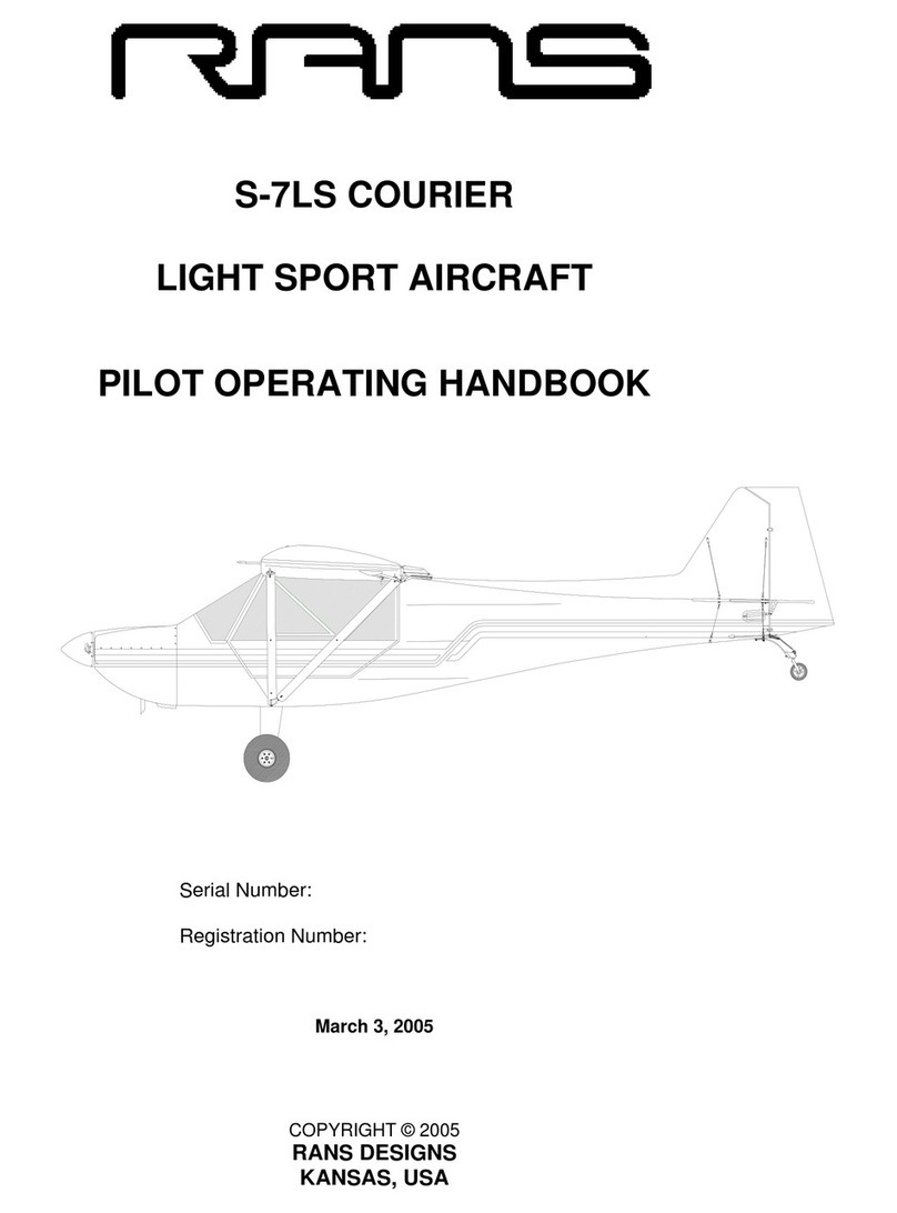
Rans S-12 Owner's manual

SPECIFICATIONS
Wing Span 31.0 ft
Area 152 sq ft
Mean Chord 4 ft 10.5 in
Aspect.Ratio 6.33:1
Length 20 ft 6 in
Height 93 in
Cockpit Width 41 in
Number of Seats 2
Landing Gear Fixed Tricycle
Fuel Capacity 18 gal US
WEIGHTS AND LOADINGS
Gross Weight 1100 lbs
Empty Weight 610 lbs
Useful Load 490 lbs
Wing Loading 7.2 lbs
Power Loading 13.75 lbs
Limit Load Factors +4 -2
POWER PLANT
Engine Rotax 912 UL 2
Output 80 hp
Oil Capacity 3.0 qts
Coolant Capacity 4.4 qts
Propeller Diameter 72 in.
Prop Type Composite 3 blade
Gear Reduction 1:2.27
Fuel G.P.H. 4.1 gal @ 80%
PERFORMANCE 0’MSL
Take Off Roll 285 ft
Rate of Climb 900 fpm
Service Ceiling 14,000+ ft
Cruise 75 mph
VNE 100 mph
Stall Clean 42 mph
Stall Flaps 37 mph
Roll Rate 70deg /sec
Glide Ratio 7:1
Landing Roll 200 ft
Endurance 4.4 hrs
Range 374 miles
Pilot’s
Operating
Handbook
Rans S-12 Airaile
Keep this copy in aircraft at all times
(Current weight and balance inside)
Aircraft Registration Number N
Airframe S-12XL Airaile Serial No.
Engine Rotax 912UL-2 Serial No.
Propeller Warp Drive 3 Blade Composite Serial No.
Intercom PS-Engineering PM501 Serial No.
ELT Ameri-King AK450 Serial No.
Fire Suppression H3R Inc. Right-Outtm 14oz Halon Serial No.

Revision Release Codes
001 Preliminary Issue of POH, issued October 27, 1999 after completion of the
FAA airworthiness inspection
002 Issued after 5 hours test flight time
003 Issued on November 16th, 1999 after completion of test pilot’s full testing phase.
This issue is for the most part complete and contains typographical errors as well as content
omissions. The next release of the POH should be a practical final release.
004 Issued January 3rd, 2000 after the test pilot had a hard landing resulting from a full
flaps high angle climbout with a (simulated) engine failure. This was an effort to expand the
operational flight envelop of the aiplane and resulted in at least one data point OUTSIDE the
airspeed/altitude envelope. New notes added to the procedures section regarding short field
and rough field operations.
005 Issued February 23rd, 2000 with a checklist reflecting the condition inspection and
updated maintenance procedures and intervals. There are also changes to the content grammar,
readability and flow. Charts have been included electronically (as opposed to ‘cut and paste’
after printing out the document). This version will be updated again to reflect content changes
to the condition inspection about to be carried out on the plane and to finalize the handbook for
grammar, readability and content.
006 Issued March 12, 2000 Includes an updated cruise checklist and procedure because
of an incident whereby the fuel was not properly feeding from both tanks during cross country
flight. Reflects updates as necessary from the 100 hour inspection conducted in March.
007 Issued ??,2000 Minor typographical fixes included.
Table of Contents
Chapter 1. Familiarization . . . . . . . . . . . . . . . . . . . . . . . . . . . . .Page 3
Learn the basic configuration and behavior of the airplane as well as the most impor-
tant operating rules regarding operation of a homebuilt experimental aircraft.
Chapter 2. Aircraft Performance . . . . . . . . . . . . . . . . . . . . . . . . .Page 4
Overview of the performance limitations such as maximum suggested crosswind,
short field takeoff distances, best angle and rate of climb configurations, and sugges-
tions as to how and when to use such configurations.
Chapter 3. Standard Procedures . . . . . . . . . . . . . . . . . . . . . . . . .Page 6
Learn the piloting procedures for almost any situation such as soft field takeoff pro-
cedures, how to start the engine, performing chandelles, etc. Includes
Chapter 4. Weight and Balance . . . . . . . . . . . . . . . . . . . . . . . .Page 11
Current weight and balance data of the aircraft including techniques and charts to cal-
culate the loading of the aircraft prior to takeoff.
Chapter 5. Airframe Maintenance . . . . . . . . . . . . . . . . . . . . . .Page 12
Learn the philosophy and procedures for maintaining the airframe, who can perform
maintenance on the airframe and how often it should be done. Though not compre-
hensive, this chapter highlights most of the important inspection points. Full, detailed
inspection procedures can only be developed over time and by a qualified mechanic.
Chapter 6. Powerplant Maintenance . . . . . . . . . . . . . . . . . . . . .Page 14
Learn the fundamentals of engine maintenance. Reference to the engine manufactur-
er’s (Rotax) documentation is highly recommended. Full, detailed inspection proce-
dures can only be developed over time by a qualified engine mechanic.
Appendix A FAA Issued Operating Limitations . . . . . . . . . . . . . . . . . . . . . . Page 15
Appendix B Manufacturer Index . . . . . . . . . . . . . . . . . . . . . . . . . . . . . . . . . . Page 16
Appendix C Pre-flight and In-flight Checklists . . . . . . . . . . . . . . . . . . . . . . Page 17
Appendix D Reference Condition Inspection Checklist . . . . . . . . . . . . . . . . Page 19
Appendix E Placards . . . . . . . . . . . . . . . . . . . . . . . . . . . . . . . . . . . . . . . . . . . Page 21
Appendix F Maintenance tools, equipment and supplies . . . . . . . . . . . . . . . Page 22
PAGE 2

Chapter 1 Familiarization
The White/Rans S-12 is a two place, high wing pusher design of low weight and moderate
horsepower. Additionally the design has a below average lift to drag ratio due mostly to the
large thick wing. The stability of this design configuration is very high. There are no signifi-
cant divergent tendencies within the operational envelope of flight.
The aircraft kit was manufactured by Rans Aircraft in Hays, Kansas. In its kit form, the air-
plane came with all welding and sophisticated fabrication completed. The majority of the
amateur build requirements are satisfied by drilling holes in components, making the finish
cuts on lengths of tubing, running wiring, hoses, etc. and assembling the pre-manufactured
sub-assemblies into the completed aircraft. All told, the number of hours spent on the amateur
build portion of this aircraft mounted to over 750.
This aircraft does not meet FAR §103.1 and thus does not qualify as an “ultralight” but instead
according to FAR §21.175, and an experimental (special) airworthiness certificate must be
issued for this amateur-built aircraft. FAR §21.191 A private or recreational pilots license is
required to fly this airplane. Because this particular aircraft is not equipped with lights, night
flying is prohibited; and because no transponder or communication radio is installed, entry
into tower controlled airspace is prohibited. If you need another reason not to fly into weather
or other limited visibility conditions, the un-certificated Rotax 912 engine on this aircraft is
restricted to daytime VFR use only. For these reasons, flight into instrument meteorologi-
cal conditions with this aircraft is STRICTLY PROHIBITED. There is an emergency locator
transmitter on-board the aircraft capable of transmitting voice and also can be easily removed
from the aircraft for portable operation should the survivors need to leave the crash site. Also,
this aircraft is prohibited from carrying passengers for compensation or hire and that does
include buying the pilot lunch and a motel at your destination.
In-flight behavior of the aircraft is very similar to other high wing designs such as the Cessna
172 with the exception that the S-12 has a considerably higher power to weight ratio (for
increased climb and acceleration performance) and a higher drag to weight ratio (when you
loose power, the aircraft has very little momentum and drag slows it down IMMEDIATELY).
The pusher prop is located above the centerline of the airframe and compared to other more
traditional aircraft such as a 172, creates a significant nose-down moment with the addition of
power and conversely a nose-up moment with the reduction of power. This tendency is high-
est for example at the time of a missed-approach. The unwary pilot, adding full power from
an idle power setting at very low altitude and low airspeed will notice a very high stick force
required to keep the nose in a climb attitude.
This airplane is quite capable of short field operations. Take-off distances of less than 300 feet
with full flaps, 1 pilot, and a 10kt headwind are possible. Likewise short landing distances
are equally possible but difficult due to minimal braking power provided by the aircraft’s inef-
ficient hydraulic braking system. Rough and soft field operations are possible but should be
avoided where possible due to the fragile nature of the aircraft. The nosegear of this airplane
is particularly susceptible to damage when mis-treated.
Intentional spins are prohibited in this aircraft. However, even a low time pilot will be able
to recover easily from stalls and avoid departures. Stalls are marked with a gentle drop of the
nose or in the case of power-on climbing banked stalls, the high wing will in fact drop (pro-
vided no pilot rudder input is used). A power on stall with only the pilot on board may be hard
to recognize and in fact may never occur. The aircraft is not intended for aerobatics of any
nature which would intentionally exceed 2G’s positive loading (4G design limit) and while the
structure is designed to ultimately sustain 2G’s negative loading, it is recommended to avoid
negative loading of any nature due to fuel starvation problems with the gravity fed fuel system.
In general, maintenance of the aircraft is focused on the powerplant (coolant, oil and other
consumables) and the fabric sails. Loosing an engine or a big patch of your wing fabric is
just about the most likely and serious threat to your well-being. The sails are coated with a
UV resistant clear which extends their life from 350 exposure hours to approximately twice
that. In any case, the sails should be treated with care; frequent detailed inspections will avoid
any catastrophic failures. Other obvious failures are equally as important such as cracking
of structural members, fatigued aluminum, missing rivets, loose bolts and elongated holes.
Maintenance of the aircraft should only be performed by the designated repairman Jim White,
but by regulation can be performed by virtually anyone. A 12 month condition inspection is
a requirement of the airworthiness certificate and can be performed only by the designated
repairman or a licensed A&P mechanic. If at any time, a major change is made, a re-inspection
by the FAA is necessitated (FAR §21.93). When ownership of the aircraft is transferred, a new
repairman certificate will need to be issued through the FAA.
A specific outline of the aircraft’s operating limitations, as issued by the FAA at time of inspec-
tion, is given in Appendix A and as a requirement must be on-board the aircraft at all times.
All pilots should be aware of the FAA issued operating limitations for this amateur built air-
craft.
PAGE 3

Chapter 2 Aircraft Performance
Overview
Comprehensive performance charts (takeoff distances, rate of climb, etc.) are difficult to devel-
op in 40 hours of flight testing. It is generally not possible within the scope of basic flight test-
ing to experience the meteorological conditions that would allow a test pilot to generate data
for all density altitudes. This factor and the general performance of this aircraft lend them-
selves to one important performance characteristic: log time in the airplane and learn for your-
self the maximum performance characteristics if you need to push the envelope. Suggestions
of climb performance and take-off and landing distances charted at the end of this chapter are
logical estimations given by the test pilot.
Operational Milestones
This aircraft has been flown to 14,000 feet MSL with a single pilot, it has been operated on
very short (300 feet), very rough fields (furrowed field), it has flown in 20 to 25 mph winds,
it has flown in formation with other aircraft, and it has been flown at gross weight of 1100lbs.
Maximum demonstrated crosswind by the test pilot during the certification phase was about 10
knots.
Typical Engine Performance
As for engine performance, it is best to review the Rotax operating manual. This manual does
a very good job of informing the pilot with respect to engine performance and engine operating
parameters. As a fundamental means to knowing engine limitations, the following apply and
were observed during the first 40 hour test period:
RPM: Maximum 5 minutes at full throttle, Maximum 5500 continuous
Oil Temp: Do not takeoff less than 130 F or operate higher than 270 F
Oil Pressure: Typically comes up to 65psi immediately and stays there
CHT: Should be at least 130 F for engine runup and typically below 200 F
Water Temp: Raises to 130 F for runup and typically below 200 F
Water Pressure: Increases to 12 psi and may drop below that in cruise
Fuel Burn: Calculate flight plans with 4.5gph fuel usage and 65mph cruise
An important consideration for engine performance figures is a result of the very effective
cooling system of this aircraft. In cold weather it becomes necessary to block off the air inlet
to the radiator to keep the engine temperatures in the green. If you notice unusually cool
engine operation in flight, the best thing to do is descend to a lower (and warmer) altitude and
land when convenient to cover up the radiator inlet.
Takeoff and Landing Distance
In most any case, the runways typically encountered at modern day airports will be far longer
than necessary for the S-12, even on a warm day at gross weight. However, the novice pilot
should not attempt to operate on low performance days near gross weight with less than 1000
feet of runway. This is a scenario reserved for the pilot who is familiar with the aircraft. If
flying solo and reasonably familiar with the airplane, 500 feet of runway (without obstacles)
will usually suffice. With 50 foot obstacles in the same conditions, for takeoff or landing, a
good pilot should give himself 750 feet of runway. If all conditions are in the pilots favor
(pilot skill, sea level, 15mph headwind, solo pilot, smooth runway, no obstacles) then 200 feet
of runway can suffice for takeoff and 300 feet for landing. The main reason for increased
landing distance is the lack of braking power.
Figure 2.1 - Take-off and Landing Distance Chart
This take-off/landing distance chart is to be used as a guide for the new pilot. All of these
distances are purely estimation (extrapolated from key data points gathered during the testing
phase) by the test pilot and should serve as a general reference only. As a pilot of this aircraft,
you should be experienced in the plane before trying to fly yourself and a friend into a remote
area at high altitudes for an afternoon of hiking. You may find youself commited to an impos-
sible landing with not enough performance to execute a go around.
Best Glide and Rate of Climb
As previously mentioned, this data was collected for one set of conditions only and best esti-
mations must be used to extract the data to meaningful numbers at different weights and alti-
tudes. This rate of climb data was collected at a take-off weight of 880lbs at an elevation of
4000MSL with an ambient air temperature of about 55 to 60 degrees fahrenheit.
As density altitude increases, two factors change the performance characteristics of the aircraft
with regard to climb rate:
Engine power output decreases as altitude increases
Propellor effeciency decreases as altitude increases
It is important to understand that both of these effects are additive and will reduce performance
to a sub-par level at high altitudes. While testing the service ceiling at around 820 pounds,
6167U was observed to have a 200fpm maximum climb rate at 14,000 indicated altitude. At
gross weight and 10,000 density altitude, you may find yourself unable to attain more than a
200 fpm climb.
Figure 2.2 - Power On Rate of Climb Chart
The conclusions reached from the power on rate of climb test data are:
1) Best available rate of climb: no flaps, 50mph IAS, 760fpm
2) Best available angle of climb, 3 notches, 35mph IAS, 650fpm
3) Safest climb (test pilot’s recommendation: no flaps, 65mph, 700fpm
Although the true best angle of climb is obtained with full flaps at 35mph indicated, this is not
the safest procedure to follow because it is right at the stall speed of the aircraft and engine
failure would be difficult to recover from. Only hours of practice and experience will allow
PAGE 4
Density Altitude Take-off Weight (lb) Obstacle Clearance (ft) Surface Condition Runway Length (ft)
0 820 0 Asphalt 500
5000 820 0 Asphalt 700
10,000 820 0 Asphalt 1500
0 1100 0 Asphalt 650
5000 1100 0 Asphalt 1000
10,000 1100 0 Asphalt 1900
0 820 50 Grass/Dirt 700
5000 820 50 Grass/Dirt 1000
10,000 820 50 Grass/Dirt 2200
0 1100 50 Grass/Dirt 900
5000 1100 50 Grass/Dirt 1300
10,000 1100 50 Grass/Dirt 2600
For any given condition: allow 10 percent runway distance increase per 1000’ density altitude chage; allow 40 percent runway
increase from smooth to rough conditions; allow 30 percent runway increase from minimum weight to gross weight; allow 8
feet per foot obstacle clearance; allow 2 percent runway distance decrease per knot headwind.

a pilot to make the decision between a climbout over a critical obstacle at 35mph followed
by a safer climb at 50mph. By spending time examining the data from the above chart, an
experienced pilot/aerodynamiscist can make several very important discoveries regarding the
configuration of this airplane, but such a discussion is beyond the scope of a simple POH. It
is recommended to simply familiarize yourself with the trends left to right and top to bottom,
understand the transitions necessary when retracting or extending the flaps as it relates to climb
angle and airspeed (kinetic energy).
In addition to the power-on data, the same chart is given below in the power off configuration
to aid the pilot in selecting the best glide speed for engine out emergencies.
Figure 2.3 - Power Off Rate of Climb Chart
The absence of data in this chart reflects the importance of knowing just how fast the airplane
can be made to descend. It is highly unlikely that it will glide better with full flaps than in any
other configuration so that area of testing was ommited. The most important conclusion from
this data is as follows:
1) Best glide no wind conditions, no flaps, 50mph IAS, 500fpm, 8.8:1, 6.5 degrees below the horizon.
Chapter 3 Standard Procedures
Overview
This chapter is by far the most detailed of the operating handbook and indeed is the primary
reason for having a handbook for the aircraft. The test pilot has spent many hours flying the
airplane and has presented here the most refined, safest, and preferred procedures for most all
flight situations. All of the procedures herein should be reviewed by a pilot new to the aircraft
in order to gain familiarization with the philosophy and methods of flying 6167U. At the same
time, realize that everything in the handbook is subject to critiscism and the test pilot’s operat-
ing procedures are no exception.
Starting the Engine
When starting a cold engine, it is of utmost importance to avoid running the motor at very low
RPM until it has warmed up. This is because it runs very rough. To start the engine when it
is cold, begin with the throttle at idle and the starting carburetor activated. The starting car-
buretor is the more appropriate name given, by Rotax, to the choke. Engage the starter until
the engine starts and immediately begin monitoring the engine instruments. Oil pressure may
jump to as much as 100psi for as long as 10 seconds, but as the engine warms up slightly, the
oil pressure will return to normal. It is important to never engage the starter for more than 10
seconds continuously and to give it a 1 minute rest period between every 10 seconds, to pre-
vent over-stressing the starter components. After the engine starts, push the throttle open until
the engine runs at about 2500 RPM and at this point go ahead and close the starting carburetor
(close the choke). This should bring the RPM back to around 2000. In any case it will require
a little ‘artistry’ on behalf of the pilot to get a stubborn engine to idle when cold. The starting
carburetor sends a specific fuel air mixture to the engine which lets it run when cold, it is only
set for a condition of throttle at idle. After starting the motor, if you close the choke before
increasing the throttle, the engine may sputter or die, which is why after a brief period of run-
ning the motor with the choke on, you increase throttle to 2500RPM and then turn off the
choke. To warm up the engine, set the RPM to 2000 for at least 2 minutes and then increase to
2500RPM until oil temperature reaches at least 120 F. Now it is possible to continue with the
run-up procedure to check engine ignition.
If you observe that there is no fuel in the fuel filter, it is best to crank the engine with the
ignition OFF until you see the filter fill at least halfway and then continue for a few seconds
(do not crank for more than 10 seconds without a break). This condition will occur after you
change the fuel filter and also if you inadvertently run the engine with the fuel valve turned off.
Cranking the engine with the ignition off will load the supply side of the fuel system with fuel
and when you finally start the motor, it will not sputter for lack of fuel, which is something
that should be avoided if possible. It is important to note that the engine will run perfectly and
the pilot may observe the fuel filter only half full, this is normal.
Engine Run-up
After the engine instruments are in the green and when you are sure the area is clear, set the
parking brake and begin the run-up procedure. Increase RPM slowly to 3750 and sequentially
turn off and then back on each of the ignition switches. Running the engine on one igni-
tion circuit only will drop the RPM by about 200. There should be a maximum drop of 300
RPM and a difference between the two ignition systems of no more than 115 RPM. It will
likely be best to judge the behavior of this check mostly by listening to the motor. After the
PAGE 5
IAS Climb Ratio Angle
35 - - -
40 600 5.86 9.80
45 680 5.82 9.90
50 760 5.79 9.95
55 750 6.45 8.90
60 700 7.54 7.60
65 680 8.40 6.80
70 620 9.94 5.70
75 600 11.00 5.20
80 425 16.56 3.46
IAS Climb Ratio Angle
35 - - -
40 700 5.03 11.50
45 700 5.66 10.20
50 700 6.29 9.10
55 650 7.45 7.70
60 600 8.80 6.50
65 600 9.53 6.00
70
75 - - -
80 - - -
IAS Climb Ratio Angle
35 500 6.16 9.30
40 680 5.18 11.10
45 750 5.28 10.90
50 620 7.10 8.10
55 620 7.81 7.40
60 600 8.80 6.50
65 650 8.80 6.50
70 - - -
75 - - -
80- - -
IAS Climb Ratio Angle
35 625 4.93 11.70
40 600 5.86 9.80
45 620 6.39 9.00
50 700 6.29 9.10
55 - - -
60 - - -
65 - - -
70 - - -
75 - - -
80 - - -
Flaps 0 Notches Flaps 1 Notch Flaps 2 Notches Flaps 3 Notches
IAS Climb Ratio Angle
35 - - -
40 - - -
45 - - -
50 500 8.80 6.50
55 700 6.91 8.30
60 800 6.60 8.70
65 800 7.15 8.00
70 - - -
75 1100 6.00 9.60
80 1400 5.02 11.50
IAS Climb Ratio Angle
35 - - -
40 - - -
45 - - -
50 550 8.00 7.20
55 620 7.81 7.36
60 650 8.12 7.10
65 900 6.35 9.10
70 1000 6.16 9.30
75 - - -
80 1500 4.69 12.30
IAS Climb Ratio Angle
35 - - -
40 - - -
45 - - -
50 - - -
55 - - -
60 900 6.35 9.80
65 900 5.86 9.10
70 - - -
75 - - -
80 - - -
IAS Climb Ratio Angle
35 - - -
40 - - -
45 - - -
50 - - -
55 - - -
60 - - -
65 - - -
70 - - -
75 - - -
80 - - -
Flaps 0 Notches Flaps 1 Notch Flaps 2 Notches Flaps 3 Notches

check, return the throttle to idle. Each of the 4 cylinders in the engine has 2 spark plugs. One
ignition circuit controls one spark plug in each cylinder. Two ignition systems increase the
efficiency of the combustion (as evidenced by an RPM drop when you turn off one ignition
switch) and secondarily provide a redundancy feature that if one circuit should fail, there is a
second system to provide adequate power to land the airplane.
Using the Parking Brake Valve
The parking brake valve, if closed while the brakes are held on, will maintain better stop-
ping power than using the brakes alone. This is because most of the hydraulic energy lost in
this particular brake system is due to the flexure of the plastic brake line. While holding the
brakes on hard, switch the valve to the closed position and release the brakes with your feet.
Now the length of brake line holding hydraulic pressure is cut approximately in half, increas-
ing stopping power. This technique should be employed for short field takeoffs and landings
where stopping power is critical. It is also recommended for run-up procedure when checking
magneto operation (the engine generates an enormous amount of thrust at mag-check RPM
of 3750). Although when the valve is closed, it does allow you to apply brakes, it is recom-
mended to hold the brakes on, then close the valve. Due to the ease with which the parking
brake valve can be closed and open, it must remain an item on all checklists. It is not wise to
takeoff or land when the valve is closed. When taxiing, use the brakes as little as possible and
avoid using them lightly for extended periods, it is better to brake hard for a short period than
to ride them lightly. If the situation ever becomes critical, cut the engine power and as soon as
the aircraft is slow enough, put the airplane off the runway on the grass, there the rolling resis-
tance is greatly increased.
High Wind Taxi Methods
Taxiing in high winds and operating on the runway with high crosswinds is no laughing mat-
ter. This is a very light aircraft and can be quite easily tipped over of thrown about by wind.
Taxi with the utmost care in control orientation and always fly with authority and decisiveness
when in high crosswinds. Once the airplane starts to tip over there is little you can do to stop
it. If necessary, treat low wind or no wind days like high wind days. If you create the habit of
continuously correcting for wind on the ground, you will likely be much safer when the winds
do come. Take the time to create a chart for yourself showing control orientation for each type
of cross wind (quartering from the front, quartering from the rear, head on, tail wind, direct
crosswind). Remember that wind blowing backwards across the control surfaces (quartering
tailwind) causes them to work in reverse of what they normally do.
Take-Off Overview
For take-off it is important for you to remember a few things. First of all, if you loose
power in a high angle climb with full flaps or even 2 notches of flaps, you will have to
IMMEDIATELY put in a large amount of nose down control inputs to maintain airspeed. It
is easy to hesitate for a second or two and in this time your airplane can go from 70mph to
30mph. Second of all, you should treat the nose gear gently. Use a generous amount of eleva-
tor control to get the weight off the nosewheel as soon as possible, this also keeps the wheel
from spinning any faster than necessary and minimizes vibration. The nose will come off the
ground at 35mph with full throttle; with the throttle at idle, it is possible to hold the nose up at
25 to 30mph. This also keeps the rotational speed down for the large front wheel which is not
in perfect balance. In high crosswind operations, you may have to compromise a bit and keep
some weight on the nose for steering until you attain enough airspeed to keep the plane aligned
with the runway.
Take-Off Procedure
Be sure your take-off checklist is complete, add power smoothly and hold a large amount of
back stick until you feel the nosewheel come off the ground. Keep reducing back pressure as
the airspeed increases so that the nosewheel remains 4-5 inches off the ground. If you keep
the nosewheel off the ground you will be able to easily feel when the plane is ready to fly. Be
careful not to pull up too hard and scrape the tail skid on the ground. Climb the first 50 or 100
feet at 65mph unless you need to clear an obstacle, in which case use the best angle of climb
speed. After reaching 150 feet, ease out the flaps (if used) and continue the climb to your
cruise altitude. Always observe the maximum flap extension speed on takeoff and landing.
If the flap lever is difficult to pull, it is because there is too much wind pressure on the flaps.
Push the nose over and reduce the throttle to cruise. When adjusting the power setting, do so
in a slow and even manner. If you treat the engine with respect, it will respond when you ask
it to. However if you rev the motor recklessly with rapid and erratic power settings, it will
likely develop abnormal wear qualities.
Just As You Leave the Ground
As soon as you are off the ground, tap the brakes and stop the mains from spinning, you may
notice a considerable amount of shaking if they are spinning fast. Liftoff speed at gross weight
and two notches of flaps is approximately 40mph indicated airspeed. Continue your climb at
Vx or Vy as required.
Engine/Throttle Usage
The airplane can be held in a climb attitude at full power setting for as long as 5 minutes.
After this period of time you should allow for a short rest period or reduce the power of
your climb. The engine is not meant to run at full power indefinitely. Also, if you are in a
prolonged decent it is wise to periodically add power for a few seconds to clear the motor
of excessive fuel build-up and provide a chance for increased circulation of fluids. Be par-
ticularly careful after idling the engine for a minute or so on final approach and then adding
power for a go-around, give the engine a moment to respond to the first 1/4” of throttle input.
Another important aspect of the aircraft is it’s excess power. With the exception of steep
climbs, no matter what attitude the airplane is in, it is possible to quickly exceed 75mph. The
throttle in this aircraft becomes just as important as any of the other controls when maneuver-
ing and typically the airplane responds very rapidly to throttle inputs.
Cowl Flaps
This airplane does not have cowl flaps but there is something to be said on this subject. After
the initial flight test period and when the weather turned cold, the typical in flight engine
parameters started running too low. This is because of the highly effective radiator and the
exposed mounting configuration of the engine. If the aircraft is operated in cold weather, the
radiator inlet should be blocked either partially or completely. A completely blocked radia-
tor inlet in operational weather of 30 degrees F will yield engine temperatures that are on the
verge of too cool. If you discover the engine running too cool (out of the green) in flight,
descend to a lower altitude and continue to the nearest point where you can land to cover up
the inlet to the radiator. Running the engine at low temperatures is not healthy.
Rudder Usage
The rudder is trimmed for most normal flight conditions, however in a low airspeed high
power setting configuration, the aircraft will require a little more right rudder pressure. In
PAGE 6

power-off descents, the aircraft will require a slight amount of left rudder. These tendencies
are a result of the required aerodynamic right rudder trim which is set for a condition of level
un-accelerated flight. The pusher prop, rotating counter-clockwise with respect to the lon-
gitudinal axis of the aircraft, is generally located above the vertical tail surfaces and as such
the prop wash hits the left side of the vertical tail causing a nose-left tendency. Corrected in
normal flight with right rudder trim, when the power is cut to idle there is an excess of right
rudder moment and the pilot must use left rudder to fly straight.
Landing Overview
To land this aircraft it is important to remember that it has very little momentum (low gross
weight) and a relatively large amount of drag (big wing). If you are doing an approach with
full flaps and no power, the decent angle will probably exceed 25 degrees and the flare should
occur at no more than one and a half feet above the surface. Why? Because if you flare early,
the airplane will slow down drastically and settle rather abruptly on to the runway. If you
don’t like steep approaches and practically non-existent flares, then don’t use flaps, keep in just
a little power, and if you want a nice gentle and long flare, round out at about 5 feet and add
power at the same time to around 3000 RPM. This is enough power to keep you from slowing
down too much and gives you some time to allow the airplane to settle gently onto the runway
by ever so slightly reducing the power setting and lowering the nose.
Powered Flare Approach
If you are doing the powered flare landing, you should touch down on the main gear with
some power (2500 RPM) and once you do, reduce the power to idle and immediately reduce a
little back pressure. Remember, the more power you have the more tendency for the airplane
to pitch nose down. Even though you are cooking along at 40mph with 2500RPM and you
can’t hardly keep the nose wheel off the ground, when you cut the power the nose will come
up immediately but the airplane will not likely lift off. Let the nose settle to the ground slowly
and keep a little reserve elevator movement for the last few inches so that you can really touch
down softly. If you hold the nose up with full elevator, the airspeed will drop suddenly and so
will the nose, with no more up elevator to stop the motion.
Aerodynamic and Mechanical Braking
For maximum braking effect when on short fields, retract the flaps at touchdown to put weight
on the mains, keep the nose high for aerodynamic braking thru 35mph, all the while using
as much brake pressure as possible without slamming the nose to the ground. When you are
under 30mph, it is best to let the nose wheel down and use maximum brake pressure.
Shutting Down the Engine (on the ground and in-flight)
After you land the aircraft and taxi off the runway, you have already provided an adequate cool
down rest period for the engine. Normally after touch down, the throttle goes to idle and there
is a certain amount of taxing involved. Set the throttle to idle, turn off both ignition circuits
simultaneously and allow the propeller to stop. If you ever decide to turn off the engine while
in flight, it is necessary to do a 30 second ‘cool-down’ run at 3000RPM prior to ignition shut
off. Cutting the engine ignition when the engine has been running at high temperatures will
cause it undue stress. Running the motor at 3000RPM for 30 seconds will circulate water and
put the engine into a state of readiness for shut down. Be sure to reduce from 3000RPM to
idle prior to turning off the ignition circuits. Follow the appropriate start up procedure for hot
or cold start when it is time to re-fire the motor. Be sure to allow suffecient pre-heat time for
the engine to warm up if you shut it off during flight in cold weather.
Emergency Procedures, Off Field Emergency Landings
In the case of an engine that will not start in flight, first focus on flying the airplane at the best
glide speed of 50mph and aiming for a suitable landing field. This is the best still-air glide
speed and essentially is the slowest sink rate. This will maximize your options in gliding to
nearby fields and give you the most time to handle the emergency. If you have enough alti-
tude, go through the checklist for engine starting by first observing fuel quantity and the fuel
valve. Try a warm engine start first and if that fails, use the choke to start the engine. All the
while, do not fail to fly the airplane and under no condition should you ever try to stretch the
glide beyond what the aircraft is capable. Many pilots are killed because they are too ignorant
to recognize that the airplane is coming down whether they approve or not. Save the stall for
the last 1 or 2 feet of altitude if the terrain is very rough. Don’t try to stretch a glide over top
of power lines, it would be better to dive under them. If you stall and/or spin the aircraft at
low altitude, the NTSB accident report will paint an ugly picture of your piloting skills. You
should have enough time after committing to an off-field landing to do the following important
steps: 1) Secure your seatbelts and 2) Un-latch the doors for a speedy egress from the aircraft.
In addition, if you are certain of a serious emergency, do not hesitate to activate the ELT on
your way down...there is no reason to wait for it to activate during the impact. Also if there is
time it would be good to shut off the main fuel valve, but this is not a requirement.
Cruise Flight Fuel Consumption
Although it will not pose an immediate problem, if one of the fuel caps were not vented cor-
rectly you will find that during flight, fuel will feed from one tank only. If both fuel caps are
improperly vented and are exposed to low pressure, the engine will likely starve for fuel before
making it to the cruise flight situation. It is highly recommended to make estimated calcula-
tions regarding fuel usage, NEVER ASSUME that the quantity of fuel indicated in one tank
is also in the other tank. If there is any indication of something that isn’t quite right, make a
cautionary landing as soon as practicable.
Cruise, Climbs and Descents
This airplane was meant to move at 65mph. Essentially everything is done at 65mph. Climb
at 65mph, cruise at 65mph and descend at 65mph. As with any aircraft, the technique is to
adjust your pitch for airspeed (elevator stick pressure) and adjust your power for the climb/
descent rate. An intelligent reader quickly notes that flying this aircraft at 65mph ALL the time
results in moderate throttle usage. Just as mentioned previously, the throttle in this aircraft is
just as important as any other control. Learn to use it just like you use your feet on the rudders
or your hand on the stick. Add power to increase your climb rate, decrease power to increase
your descent rate. If you are flying too high, don’t just push the stick forward but also reduce
the throttle. If you are too low, don’t just pull the stick back but also add power. The plane
will cruise most comfortably at around 65mph indicated airspeed but cruising at 70, 75 or even
80mph is easy because of the excess power. Respect the yellow range marking on the airspeed
indicator because it is there for a purpose. Higher speeds are reserved for only the smoothest
of air.
Pitch Trim
There are two forces that trim the aircraft in its pitch attitude: power and elevator/horizontal
stabilizer position. Understand that adding power will add a nose down trim to the airplane
and reducing power will add a nose up trim to the airplane (remember the thrust line of the
engine is above the center of the airplane). Also understand that increasing airspeed adds a
PAGE 7
nose up trim and decreasing airspeed adds a nose down trim (due to the decalage settings of
the horizontal stabilizer, designed to produce negative lift at cruise airspeeds). The point of
this discussion is that the aircraft, by design, will fly approximately level (not climbing or
descending) regardless of the power setting. If you are holding forward pressure or back pres-
sure on the airplane to maintain level flight, chances are you have displaced the trim tab or you
are at the wrong speed for the power setting. Don’t fight the aircraft, allow it to establish an
equilibrium before you start to second guess the trim setting.
Add power: the power creates a pitch down moment which increases airspeed. The increased
airspeed thus creates a pitch up moment and the aircraft balances at a new higher, cruise speed.
Reduce power: the loss of power creates a pitch up moment which decreases airspeed. The
decreased airspeed thus creates a pitch down moment and the aircraft balances a new, lower,
cruise speed.
The balance of these forces will change depending on the location of the center of gravity of
the aircraft. Be prepared for unusual (more appropriately ‘unfamiliar’) behavior when you fly
the airplane in different loading conditions. Visualize the dynamics of trim and energy balance
while in flight to help you understand the interaction between pitch trim, power settings and
airspeed.
Steep Turns
Steep turns (60 degree bank) are an approved maneuver in the S-12 and pose no particular
threat with the pilots prior understanding of the aircraft’s behavior.
Remember that one of the most distinguishing characteristics of this plane is that it has very
little momentum because of its low weight. Because of this, it does not have the energy neces-
sary to carry it through a turn. To change the direction of the airplane from straight and level
requires acceleration, and acceleration requires energy. In a larger airplane, a slight increase
in throttle is enough energy for the turn because a certain amount can be robbed in the form
of airspeed, without jeopardizing the safety of the maneuver. In the S-12, the energy to turn
is far greater with respect to the stored energy of level flight (momentum) and will rapidly
decrease airspeed to the point of a stall. The remedy is to dive rather sharply during the turn or
to increase power as you begin banking the airplane. Practice will tell you how much power is
required, but for all practical purposes, from a cruise of 65mph, you should imagine adding full
power throughout the turn to maintain your altitude. Failure to do so will drop airspeed well
below 50mph.
Auto-Steepening Tendency
During the flight testing phase the aircraft was put through nearly every conceivable flight atti-
tude likely to be encountered by the average pilot in most conditions. The plane was not tested
for aerobatics and other such maneuvers but during testing, one significant flight mechanics
tendency was noticed. After banking into a turn more than about 20 degrees, a certain amount
of opposite aileron pressure is required to keep the bank from auto-steepening. This charac-
teristic is due in part to the large wing and low airspeed. In a tight turn at 65mph indicated
airspeed, the outside wing is traveling significantly faster than the inside wing and as a result
has more lift. The remedy is to use a slight amount of opposite aileron. The effect increases as
the radius of the turn decreases (low airspeed steep banks will create the most dramatic tenden-
cies). This can be a dangerous characteristic when flying at low altitudes in gusty winds so be
sure to understand the aircraft intimately before taking it to low altitudes.
Power-Off Stalls
Stalls in the Rans S-12 are docile and easy to recover from. Immediately after bring the power
to idle, the nose must be aggressively raised to get a stall in the normal attitude. If the nose is
not brought up immediately and quickly, even full up elevator will not bring the nose up to the
horizon and the plane will stall with a nose low attitude. Either way, recovery from the stall is
immediate following reduction of back pressure and the addition of power. There is very little
buffeting or any other pre-stall warning. If the airplane is in a coordinated turn (climbing or
diving) and the stall occurs rapidly enough, the high wing will drop bringing the aircraft to a
level bank attitude when the stall occurs. This behavior is the same when flaps are applied.
Power-On Stalls
Power-on stalls are equally as easy to recover from and require a healthy amount of back stick
to perform, especially with only one pilot at lower density altitudes. At low takeoff weights
and in high density air, the plane may not stall with full power and could simply mush along
at a very nose high attitude. There will be a considerable amount of noise and buffeting of the
aircraft and it will require an excessive amount of back pressure to keep the airplane in this
near-stall condition, which is instantly recovered from by reducing back stick pressure.
Skid and Slip Stalls
While not intended to be everyday maneuvers, stalls in slip or skid configurations possess no
violent tendencies to spin but do require special pilot skill and as such are not recommended
in most cases. The S-12 for all practical purposes has shown its ability to recover from such
a maneuver and that is about the extent of telling you about it in this manual. Stalls should
never be performed intentionally with the plane not in coordinated flight, to do so unknowingly
is the first indication of a pilots lack of skill and awareness.
Stall Recovery Procedure
The standard stall recovery procedure is as follows: Stick forward, full power, retract flaps and
immediately bring the nose up as airspeed hits 55mph. Stalls will result in no more than 500
feet of altitude lost, with proper piloting skills recoveries of less than 200 feet are common.
Forward Slips
The S-12 seems to behave rather erratically in forward slips and exhibits signs of instability
and divergence. For example after depressing the right rudder to get into a slip, the rudder
pedal practically keeps itself depressed at low airspeeds, a condition called “overbalance.”
This airplane is capable of slips and they do allow the pilot to quickly loose altitude but again
this is an advanced maneuver for skilled pilots only. The flight instruments are not accurate in
a forward slip. Practice slips at a higher altitude and use them only when comfortably above
the ground. Do not use slips for the last 500 feet of your decent to land.
PAGE 8

The Falling Leaf Maneuver
A falling leaf maneuver can be done by an advanced pilot provided there is sufficient altitude
to recover from an unwanted departure (spin). Remember this plane is prohibited for inten-
tional spins and if you are uncomfortable with your ability to keep the plane out of a spin, then
don’t do a falling leaf. It is a mildly violent maneuver and does cause some significant stress
on the airframe, thus should not be a regular maneuver or one that an amateur pilot toys with.
Bring the nose up and add a slight amount of power (2500 or 3000RPM), keep the stick nearly
full back to keep the plane in a stalled attitude. Use the rudder pedals to maintain directional
control by “stabbing” them with your feet. DO NOT push a pedal down and hold it down. If
the plane banks left, stab the right rudder and immediately release it, then be prepared for stab-
bing the left rudder. This maneuver can quickly accelerate into a spin with improper use of the
rudders by the pilot. If you loose positive control of the falling leaf maneuver, immediately
push the stick forward and recover from the stall. It will take a lot of practice to learn the
ability to “predict” which rudder pedal to push and how hard to push it. Falling Leaf is more
magical than it is aerodynamically balanced.
Spins and Spin Recovery
While the S-12 is prohibited against intentional spins, it is the test pilot’s best recommendation
to follow this technique to recover from unintentional spins:
1) throttle to idle and let go of the stick (or stick to neutral)
2) retract flaps (if extended)
3) apply rudder full opposite the direction of yaw
4) push the stick forward the amount necessary to unstall the wing
5) recover from the dive with no more than a 4G pull-up
Though not tested on N6167U, recovery from an unintentional spin using the above procedure
should yield prompt and decisive control of the situation.
Lazy Eights and Chandelles
While they were performed in the flight testing phase, these maneuvers are not recommended
in the S-12 until the pilot has had some aerobatic training. The S-12 is a fragile aircraft and
for the most part, if you are very aware of airspeeds and G-forces, you can execute some rather
enjoyable chandelles and lazy eights. However, a low time pilot with no understanding of
aerobatics may be quickly overwhelmed with either maneuver and inadvertently overstress the
aircraft. Use common sense when approaching these maneuvers.
Rough Field Operations
The Rans S-12 Aircraft is equipped with what the factory calls “tundra tires”. While they do
allow the airplane to operate from soft and rough fields, they do not indicate that the airplane
is well suited for this type of field. The particular concern with rough fields is the nosewheel.
For example, after touchdown on a rough field, it is better to taxi the remaining distance
required at 30mph with the nose off the ground than it is to taxi at 5mph with the nose on the
ground. It will take only one rough field operation to make the pilot aware of this, there is
a great deal of noise coming from the nosegear on rough fields. The rough field procedure
begins far before touchdown. Use full flaps to get the slowest touchdown speed and attempt to
hold the plane 2 inches off the runway until it settles down. Use as much back pressure as nec-
essary to keep the nose off the ground. Similarly on take-offs, the pilot should hold in FULL
back stick until the nose comes off the ground, then only use the amount of pressure required
to keep the nose off the ground. Use two notches of flaps for rough field take-offs. Three
notches may provided a ‘lighter’ feel but requires some special skills and is for the advanced
pilot. Engine failure near the ground with full flaps in a nose high attitude will result in a very
hard landing. Force the airplane off the ground as soon as possible and then fly the airplane
in ground effect until it accelerates to an acceptable climb-out speed. Steep climbs at low air-
speed with flaps extended should be avoided in all but the absolutely necessary cases.
Short Field Operations
Short field landings are about 30 to 40 percent longer than they need to be because of the inad-
equate braking system. Even with poor brakes, the S-12 can be comfortably operated in most
any condition on a 1000ft runway. Although at the time of print, this aircraft hasn’t been tested
at gross weight on a hot, humid day, the test pilot can comfortably report that 1000ft is enough
distance (even on a grass runway) to takeoff and land over 50 foot obstacles, provided the pilot
is of moderate skill. In many cases, with a skilled pilot operating at 3000 feet density altitude
and without a passenger on board, 500 feet of runway is comfortably sufficient, provided the
50 foot obstacle does not have to be cleared. For a short field take-off, use two notches of
flaps. An alternate technique for short field lift-off is to use three notches of flaps but this is
kind of an extreme measure and can lead to an accident if things go wrong. Hold the brakes as
hard as you can and run the power up to where the airplane is barely able to stand still. Then
quickly release the brakes while at the same time pushing the throttle to full power. Keep the
elevator essentially in the cruise setting for the most aerodynamic takeoff roll. If it is a rough
AND short field then keep the elevator horizontal until you reach 20mph and then briskly and
gently use it as necessary to get the nose off the ground. After the aircraft leaves the ground,
climb at the best angle of climb speed of 40mph. When you are clear of your obstacles (if
any), continue the climb at a safer speed of 65mph and retract the flaps slowly.
PAGE 9

Chapter 4 - Weight and Balance
The reference datum for weight and balance is at the center of the front wheel and with the
aircraft level, all arms and weights are measured rearward from there. Changes to standard
equipment require calculation of the weight and moment and a new ‘current’ weight and bal-
ance sheet should be printed, the old sheet being marked as “superceded.”
Installed Equipment, N6167U
Airframe White/Rans S-12XL Airaile Serial No. 04970797
Engine Rotax 912UL-2 Serial No. 4403068
Propeller Warp Drive 3 Blade Composite Serial No. T7760
Intercom PS-Engineering PM501 Serial No. XA-07690
ELT Ameri-King AK450 Serial No. 458 470
Fire Extinguisher H3R Right-Out 14oz Halon Serial No. V-162233
Weight and Balance 11 Oct, 1999
Weight Empty with full oil and antifreeze and no fuel: 610 lbs, Gross Weight 1100 lbs, Useful Load 490 lbs
Weight Arm Moment
Preflight Take-Off Weight and Balance Worksheet
Use the graphs on the following page to lookup the moments for each item. Mandatory data in [] optional in ()
Weight Arm Moment
If combined pilot and passenger weight are between 108 and 345 pounds that CG will be
acceptable regardless of fuel conditions. However, flying at the aft CG limit requires adjust-
ment of the horizontal stabilizer and hence as suggested by the test pilot, a solo pilot should
use 50 or 75 pounds of ballast when operating this aircraft. Failure to do so will impose severe
limits on the amount of nose down force available even with full forward stick. In any case,
always test the authority of the elevators by doing a short crow hop. The center of gravity
of the aircraft is the total moment divided by total weight and must fall within 69.5 and 76.5
inches (aft of the datum). The CG envelope is graphed on the following page, a point inside
the hatched region is safe with respect to loading.
PAGE 10
Rear tailwheel 14 lbs +214 in 2,996 lb*in
Left Main 298 lbs +78 in 23,244 lb*in
Right Main 298 lbs +78 in 23,244 lb*in
Empty Aircraft Totals 610 lbs +81 in 49,484 lb*in
Empty Aircraft 610 lbs +81 in 49,484 lb*in
Optional Ballast 75 lbs +20 in 1,500 lb*in
Pilot [ ] +49 in [ ]
Passenger [ ] +49 in [ ]
Fuel [ ] +78 in [ ]
TAKE-OFF [ ] ( ) [ ]
Acceptable CG Arm (Total Moment / Total Weight) is +69.5” to +76.5”

PAGE 11
420
390
360
330
270
240
210
180
120
90
60
30
450
300
150
0
19
18
17
16
14
13
12
11
9
8
7
6
4
3
2
1
20
15
10
5
0
Moment (1000*in*lb)
Weight (lbs)
Pilot and Passenger, 49 in. Aft
Fuel, 6 lb/gal, 78 in. aft
18 gal.
5
Figure 4.1 - Find the moment of pilot and passenger by moving horizontally from total weight to the pilot/passenger line, then
read down to moment. Find fuel pounds and moment by reading along the fuel line to the total fuel on board in gallons, read fuel
total weight at left and moment at bottom.
1,120
1,090
1,060
1,030
970
940
910
880
820
790
760
730
1,150
1,000
850
700
83
81
79
77
73
71
69
67
63
61
59
57
53
51
49
47
85
75
65
55
45
Moment (1000*in*lb)
Weight (lbs)
Allowable CG
69.5• -76.5•
Gross Weight, 1100 lbs.
NORMAL CATEGORY

Chapter 5 - Airframe Maintenance
Overview
MAINTENANCE OF THIS AIRCRAFT CAN BE CARRIED OUT BY NEARLY
ANYONE, HOWEVER A REQUIRED “CONDITION INSPECTION” EVERY 12
MONTHS CAN ONLY BE PERFORMED BY THE HOLDER OF THE REPAIR-
MAN’S CERTIFICATE FOR THIS AIRCRAFT (N6167U) OR A LICENSED A&P
MECHANIC.
This condition inspection is carried out in much the same manner as an “annual” that produc-
tion airplane owners are used to. Certificated parts, such as a certified engine, or other parts
certified for use on an airplane automatically are designated as unapproved when installed and
operated on an amateur-build aircraft. For this very reason, airworthiness directives do not
legally apply to this aircraft unless the directive specifically cites N6167U as non-compliant.
These technicalities notwithstanding, it would likely be foolish to disregard a factory AD on
any component of the aircraft. The safety of this aircraft rests primarily on the owner/operator
and designated repairman, not the FAA and not the engine or airframe manufacturer. Use com-
mon sense and show respect for the aircraft.
It is recommended to conduct an inspection which is the equal of a condition inspection, at 100
hour intervals. Of course when performed for a 100 hour interval purpose, the inspection does
not need to be carried out by the designated repairman.
As the reader might expect, this listing of maintenance is not comprehensive. Refer to records
kept in the aircraft logbook for additional practicle maintenance information. In most cases if
something requires periodic maintenance, the mechanic will make a meaningful entry in the
logbook reflecting what he/she has discovered.
Builder Key Areas
The pulley mount behind the left seat for the aileron cable was not manufactured properly and
may allow the pulley to ‘cam over’ into a non-free state whereby friction and control integrity
are severely compromised. As an effort to reduce the magnitude of this effect, the hoop was
bent slightly. This hoop should be inspected after the first hour, then doubling the interval until
it reaches the 100 hour point at which it is included in every 100 hour inspection.
The nut plates for the 3/16” bolts retaining the tail boom were noticed to behave in an unfa-
miliar fashion, due primarily with the builders inexperience with such fragile hardware and as
a result all 3/16” AN hardware used to mount the tailboom to the main fuselage cage should
be inspected at 5 hour intervals until the first 100 hours at which time they will be included in
every 100 hour inspection.
The mounting points for the control stick were slightly misaligned due in part to to an error
by the kit manufacturer and as a result the control stick may exhibit binding or galling when
moved fore and aft (elevator). The control stick (primarily elevator control movement) should
be inspected at 5 hours then every 25 until the 100 hour point at which time it remains on the
100 hour inspection list. This included the collar at the foremost part of the tail boom where
the elevator control rod passes thru to connect to the push-pull tube. This collar should be
lubricated with anti-seize at intervals of 25 hours or 1 year.
The manufacturer’s design of the rudder pedal and brake system (including the floor panel to
which it is mounted) is such that a great deal of stress is placed on key hardware. The bolts
used to secure the rudder assembly to the floor pan produce undue force and may eventually
cause failure of the mounting tabs or other associated hardware. This entire sub-system should
be inspected (under load) to ensure it’s integrity at 25 hour until reaching the 100 hour mark at
which time it will remain on the 100 hour inspection list.
The lower strut attach points were necessarily modified when it was discovered the
OEM equipment provided for less than 6 threads of engagement. The blocks into which the
ball joint for the rear strut lower attach point engages were manufactured to new specifications
from 4130 material and such that over 20 threads were engaged. The threads in this block
were NOT roll formed but instead cut and as a result must be inspected closely. This inspec-
tion necessitates removal of the bolt thru the rod end (and subsequent replacement of the lock
nut after 3 uses) and will remain on the 100 hour inspection list.
The jury struts don’t fit too great and have a lot of slop where the pins attach them to the main
struts. As a result of this mis-fit, it is anticipated that there will be some play and movement
in the system. At 10 hours then every 25 hours the safety wire should be cut, the pins removed
and the pins and holes inspected for wear until reaching the 100 hour mark at which time it
will remain on the 100 hour inspection list.
Periodic Inspection Points (100hr, Condition Insp., etc.)
Most items of inspection that are listed in the condition inspection checklist in Appendix E
should be included in the 100 hour inspections. In some respects this is unjustified but because
this aircraft is not built overly strong and because of the nature of the kit-build process, it is
wise to inspect everything closely after 100 hours, afterall that amounts to about 6,500 miles.
The wing struts should be inspected thoroughly (spend 15 minutes) every 10 hours. This
includes all bolts, safety wire, cotter pins etc. The struts, because they are extruded aluminum,
are particularly sensitive to nicks, dings and scratches. Look carefully for sings of wear par-
ticularly at the ends of the struts where hardware is mounted. The integrity of the jury struts is
also critical because failure of a jury strut could very quickly and violently lead to buckling of
a main strut. The plates and mounts to which the struts bolt on the wings and on the fuselage
are equally as important. Failure of the pin at the lower strut attach point, for example, would
lead to immediate loss of one wing and departure from controlled flight (serious injury or death
would follow). Likewise the integrity of the tail boom and each individual component of the
tail is critical to maintaining controlled flight. Failure of the boom or of a major component of
the tail (i.e. the tail boom extension) will cause departure from controlled flight.
The hinge bolts with castle nuts and cotter pins should be removed every 100 hours and
remain on the 100 hour inspection list. These bolts undergo a large amount of stress, fatigue
and especially wear considering the installation. It would not be unlikely for the bolts OR the
cages (hinge brackets) to show significant wear. Immediate replacement of the hinge bolts or
brackets should be carried out at the first signs of significant wear. Note also that after several
replacements of the hinge brackets, the nutplate on the inside of the wing spar will be beyond
it’s life limit and will have to be replaced. This level of replacement can be done only by
removing or cutting the wing covers and should be scheduled to coincide with the replacement
PAGE 12

of the airplane’s sails. Removing a bolt will necessitate replacement of a cotter pin for the
castle nut.
In any case, after the airplane’s first 100 hour inspection, all self-locking nuts removed for the
inspection shall be replaced. Bolts will be replaced on a wear indicated basis. Thereafter the
life of the nuts is to be set at 5 cycles (1 cycle is removal and installation of the nut). After the
5th cycle for the nut, it shall be replaced. Replacement scheduling based on hours of operation
will be based on how frequently the nut is removed for inspection purposes.
One of the fuel lines on the engine was over-tightened (hose clamp on rubber hose) and caused
immediate cracking of the hose. This was noticed after 1hr of operation in taxi tests and the
end of the hose was cut and re-clamped, this time with lighter pressure. This should remain an
inspection point for all hoses! Do not over tighten anything.
Every 15 hours, a light machine oil should be used on all control surface hinges, control mech-
anisms and rudder pedals. If it has been more than one month but less than 15 hours flight
time, the lubrication should be done prior to the next flight. The heim ends do not need lubri-
cation. Essentially the most important places to lubricate are those with extremely high pres-
sure (the aluminum bushings in the flap lever assembly, the rudder pedals, the control surface
hinges, etc.) It is best to use anti-seize lubricant on the elevator push-pull tube bushing. Also
use an extreme pressure grease on the nosegear strut every 150 hours or 12 months. Be sure
to thoroughly clean off the old grease, this is a highly exposed area and gets a good amount of
dirt inside.
Hydraulic brake fluid level should be checked with a flashlight every 25 hours and of course at
100 hour and condition inspection intervals as well. Before every flight, a quick glance to see
if there is air in the line coming from the bottom of the hydraulic resevoir is sufficient.
Washing the aircraft
Wash the aircraft using a soft sponge and a garden hose or bucket. Be very careful with the
hose and where you spray water. For the most part, if you avoid spraying directly near holes
and joints and so forth, the water will find it’s way out of the plane. After washing the aircraft,
a good automotive wax will help protect the airplane from the elements. A good wax to use is
Zymol. Whatever the case, follow the manufacturers recommendations when waxing. Some
of the do’s and don’ts of washing:
1) DO NOT spray water near the engine, especially behind the oil tank
2) DO NOT spray water near the pitot/static tubes
3) DO NOT spray water in holes or cavities where it will not readily drain
4) DO use a sponge and mild soap if necessary to scrub the airplane
5) DO use an air blower to remove excess water from joints, bolts, etc.
After the Lexan has dried, use an approved Lexan cleaner and polish to buff out minor scratch-
es, Maguires makes a cleaner and polish to buff out scratches and protect the surface very well.
Vacuum the interior of the aircraft as needed and use a dampened cloth to clean the interior
components such as the cabanes and fuselage cage. It may be handy to use the air blower to
free some of the debris trapped in the cracks of the cabin area, just use good judgement with
regard to this process, don’t blow the dirt somewhere where it can’t be vacuumed out. Another
good trick is to gently tap on the outer skin of the cabin, this will let the debris work it’s way
out from between the frame and the aluminum skin. If there are chemical spills then use the
necessary solvents to clean up the spill being especially careful around Lexan and other plas-
tics.
Because you don’t want to wash the plane any more than necessary, if you wish to remove a
light layer of dust that has accumulated, the best way to do so is with a soft, wet towel. Take
a real light pass across the surface with the cloth to get most of the dust onto the towel and
then continue with a little bit harder “buffing” motion. Being wet, the towel keeps you from
scratching the clear coat and if you are very very gentle, you can use the same wet towel to
clean off the lexan if you desire but it is best to rinse the lexan surfaces with water. If you
do not have the capacity to rinse the Lexan clean without touching it, use an air blower to get
most of the dust off prior to wiping it with a soft wet towel. Try not to buff the Lexan any
more often than necessary, just do it once a month if you can get away with it.
PAGE 13

Chapter 6 - Powerplant Maintenance
Overview
As the reader might expect, this listing of maintenance is not comprehensive. Refer to records
kept in the engine logbook for additional practicle maintenance information. In most cases if
something requires periodic maintenance, the mechanic will make a meaningful entry in the
logbook reflecting what he/she has discovered.
Propeller
“Re-torque all bolts after first hour of operation and then after every 5 to 10 hours as part of
regular maintenance.” -Warp Drive Inc. Instructions
Torque 1/4” bolts to 125 inch-pounds (25 increment) using 7/16” wrenches and 5/16” bolts
to 175 inch pounds (25 increment) using 1/2” wrenches. Periodically check the track of the
blades after torquing the blades or hub bolts. The three blades should track well within 1/8” of
each other and if they don’t, then something is wrong. Should the prop need to be re-adjusted,
the most accurate method is to remove it from the airplane and place it on a perfectly flat table
to adjust the pitch of each blade. Do so in a scientific manner to avoid any possibility of mal-
adjustment. As well the prop should be inspected briefly prior to each flight to ensure it is in
good condition. Always turn off the ignition before rotating the prop by hand and also remem-
ber that just because the switch is off doesn’t meant the engine won’t start! Excessive debris
encountered during ground operations will cause nicks and gouges in the prop compromising
it’s integrity. At the first sign of trouble the prop should be sent to the factory for repair. If
known debris conditions will be routinely encountered, the protective leading edge tape should
be installed. Blade tip speed on this particular aircraft is approximately 500mph at 5800
engine RPM, 2.2727 reduction ratio to the propellor.
Engine Mount
Torque the 10mm bolts (TYP 4) using a 17mm wrench to 40 lb*ft. Check that the barry
mounts are tight using a 9/16” wrench. This maintenance should be done at least every 50
hours.
Engine
Most engine maintenance is done by reference to the ROTAX owners manual! Always check
the fluid levels and the quality of the fluids. Replace more often if desired, do not operate
the engine with too much or too little fluid or with damaged fluids (burnt oil, dirty antifreeze,
contaminated fuel, etc). The oil and oil filter should be changed every 100 hours by using the
drill motor operated pump. Warmup the motor so that indicated oil temperature is about 120F.
Remove the oil tank cap and dipstick and insert a small diameter tube to the bottom of the oil
tank thru the dipstick hole. Pump out all oil possible (approximately .66 gallons). Remove
the oil filter carefully avoiding any excessive spills by placing rags underneath and having the
necessary clean up items on hand. Not too much oil will come out but enough to make a mess
if you don’t plan ahead. Wipe a small amount of clean oil around the rubber gasket of the new
oil filter and install it to the engine without pre-filling it. Fill the oil tank to the midpoint of
the marked region on the dip stick. Be sure the ignition is turned off and slowly rotate the prop
5 to 10 revolutions to fill the oil filter and oil pump. Now start the engine and monitor the oil
pressure very closely. Shutdown the engine after 30 seconds or 1 minute and again check the
oil level in the sump tank, add more oil if necessary. Do not overfill, it only takes about .2 gal-
lons to go from low to high point on the dip stick.
This engine has been run-in with standard 10W-40 oil?? from 0.9 hours (new hobbs meter)
to 25.0 hours at which time the oil used is switched to Mobil1 synthetic. It is important to
remember that the Rotax 912 is not designed to run with aviation oil, with or without additives.
Aviation grade oils typically have special additives that are not intended to be used in gearbox
systems and the 912 UL has a common reservoir of oil for the engine and the gearbox. This
engine was designed to be used with automotive grade oils only.
Change the fuel filter every 100 hours. Turn off the fuel valve and be prepared to catch excess
fuel that runs out of the lines. Inspect the fuel filter to the extent possible to monitor signs of
fuel system trouble. It is a good idea to monitor the condition of the fuel tanks (debris floating
in the bottom) and to thoroughly inspect the fuel lines for cracks or other problems.
Throttle
The throttle friction block and mechanism in the cockpit should be inspected for proper opera-
tion before every flight. It is a simple matter to open the throttle and then return it to idle to
observe if one or both of the cables may be sticking. On the 15 hour interval of airframe lubri-
cation, the red plastic block should be lubricated and the throttle should be operated several
times to ensure exact operation of the cable system. Likewise the choke (starting carburetor)
should be inspected at the same time. Every 100 hours, the throttle and choke cables should
be re-adjusted as well as the idle stop screws, if necessary, to synchronize the throttle opening.
This is done with a dual vacuum gage setup attached to the intake manifold ports on each car-
buretor; it is necessary to completely remove the intake manifold cross tube for this test.
PAGE 14

Appendix A FAA Issued Experimental Operating
Limitations
This is a reprint of the operating limitations issued by the Designated Airworthiness
Representative at the time of aircraft certification.
Phase I - Initial Flight Test in Restricted Area:
1. No person may operate this aircraft for other than the purpose of operating amateur-built aircraft to
accomplish the operation and flight test outline in the applicant’s letter, dated 06/10/99 in accordance
with FAR Section 21.193. Phase I and II amateur-built operations shall be conducted in accordance
with applicable air traffic and general operating rules of FAR Part 91 and the additional limitations
herein prescribed under provisions of FAR Section 91.319.
2. The initial 40 hours of flight shall be conducted within the geographical area excluding...
3. Except for takeoffs and landings, no person may operate this aircraft over densely populated areas
or in congested airways.
4. This aircraft is approved for day VFR operation only.
5. Unless prohibited by design, acrobatics are permitted in the assigned flight test area. All acrobatics
are to be conducted under the provisions of FAR Section 91.303.
6. No person may be carried in this aircraft during flight unless that person is required for the purpose
of the flight.
7. The cognizant FAA office must be notified and their response received in writing prior to flying this
aircraft after incorporating a major change, as defined by FAR Section 21.93.
8. The operator of this aircraft shall notify the control tower of the experimental nature of this aircraft
when operating into or out of airports with operating control towers.
9. The pilot-in-command of this aircraft must, as applicable, hold an appropriate category/class rating,
have an aircraft type rating, have a flight instructor’s logbook endorsement, or possess a “Letter of
Authorization” issued by an FAA Flight Standards Operations Inspector.
10. This aircraft does not meet the requirements of the applicable, comprehensive, and detailed airwor-
thiness code as provided by Annex 8 to the Convention of international Civil Aviation. This aircraft
may not be operated over any other country without the permission of that country.
Phase II - Flight Operations After Completion of Test Phase
Following satisfactory completion of the required number of flight hours in the flight test area,
the pilot shall certify in the logbook that the aircraft has been shown to comply with FAR Section
91.319(b). Compliance with FAR Section 91.319(b) shall be recorded in the aircraft logbook with the
following or similarly worded statement:
“I certify that the prescribed flight test hours have been completed and the aircraft is controllable throughout its
range of speeds and throughout all maneuvers to be executed, has no hazardous operating characteristics, or design
features, and is safe for operation.”
The following limitations apply outside of flight test area:
1. Limitations 1, 3, 7, 8, 9, and 10 from Phase I are applicable.
2. This aircraft is approved for day VFR only, unless equipped for night VFR and/or IFR, in accor-
dance with FAR Section 91.205.
3. This aircraft shall contain the placards, markings, etc., required by FAR Section 91.9.
4. This aircraft is prohibited from acrobatic flight, unless such flights were satisfactorily accomplished
and recorded in the aircraft logbook during the flight test period.
5. No person may operate this aircraft for carrying persons or property for compensation or hire.
6. The person operating this aircraft shall advise each person carried of the experimental nature of this
aircraft.
7. This aircraft shall not be operated for glider towing or parachute jumping operations, unless so
equipped and authorized.
8. No person shall operate this aircraft unless within the preceding 12 calendar months it has had a
condition inspection performed, in accordance with FAR Part 43, Appendix D, and has been found to
be in a condition for safe operation. In addition, this inspection shall be recorded in accordance with
Limitation 10, listed below.
9. The builder of this aircraft, if certificated as a repairman, or an FAA certified mechanic holding an
Airframe and Powerplant rating, may perform condition inspections, in accordance with FAR Part 43,
Appendix D.
10. Condition inspections shall be recorded in the aircraft maintenance records showing the following
or a similarly worded statement:
“I certify that this aircraft has been inspected on (insert date) in accordance with the scope and detail of Appendix
D of Part 43 and found to be in a condition for safe operation.”
The entry will include the aircraft total time-in-service, the name, signature, and certificate type and
number of the person performing the inspection.
PAGE 15

Appendix B - Manufacturer Index
Warp Drive, Inc.
1207 Highway 18 East
Ventura, Iowa 50482
(515) 357 6000
FAX (515) 357 7592
(800) 833 9357
Warp Drive 3 Blade 72” S/N T7760
Rans Aircraft, Inc.
4600 Highway 183 Alternate
Hays, Kansas 67601
(785) 625 6346
FAX (785) 625 2795
www.rans.com
S-12XL Airaile S/N 04970797
VDO Instruments
188 Brooke Rd.
P.O. Box 2897
Winchester, Virginia 22603
(540) 665 2428
2 1/16” Tachometer S.O.#08074
www.vdona.com
PS Engineering Inc.
9800 Martel Road
Lenoir City, Tennessee 37772
(423) 988 9800
FAX (423) 988 6619
www.ps-engineering.com
PM501 Intercom S/N XA-07690
Ameri-King Corporation
18842 Brookhurst Street
Fountain Valley, California 92708
(714) 963 6977
(714) 963 6200
AK-450 ELT S/N 458 470
Rotax Authorized Distributor
Leading Edge Airfoils, Inc.
8242 Cessna Drive
Peyton, Colorado 80831
(719) 683 5323
(719) 683 5333
Rotax 912 UL 2 Engine S/N 4403068
www.leadingedge-airfoils.com
H3R Incorporated
1810 Harrison Street
San Francisco, California 94012
Right-Outtm 14oz. Halon S/N V-162233
www.h3r.com
PAGE 16

Appendix C - Preflight Inspection
PAGE 17
Cockpit
AROW (airwor./regist./oper./weight)
Control Lock remove (seatbelts)
Fuel (quantity)
Sump Drain (open to drain water)
Flaps (extend)
Master Switch (cycle, check for power)
Ignition (both off)
ELT (latched, armed)
ELT lanyard & portable antenna (on-board)
Optional Ballast (installed, secured)
Cockpit Control Systems and Structure
Pedals (stops, bolts, rivets, cracks, stops)
Stick (binding, stops, push/pull tube bolt)
Cables (thimbles, tension, pulleys, fraying)
Brakes (air, fluid quantity, hoses, fittings)
Aileron T (condition, turnbuckles, safety)
Flaps (safety wire, bolts, binding)
Throttle (friction, pins, bolts, idle)
Choke (movement, friction)
Fuselage Cabanes (nicks, dings, scars)
Seats (tight, adjustment pins secure)
Fuel Lines (chaffing, clamps, leaks)
Electrical (chaffing, loose, cracks, burning)
Right Wing
Fuel (quantity, cap tight, vent forward)
Fabric (tears, UV damage, zippers closed)
Fairings (secure)
Attachment Bolts (tight, condition)
Flap (hinges, pins, pushrod, horn)
Aileron (hinges, pins, pushrod, horn)
Tip (buckling)
Struts (bolts, pins/wire, nicks, jury struts)
Center Cover (secure)
Right Main Gear
Leg (cracks, bends, brake line, hoses)
Brake (leaks, safetywire, bolts)
Tire (inflated)
Wheel (bolts, cotter pin)
Belly
Radiator (debris, leaks, damage)
ELT antenna (condition)
Right Fuselage
Lexan (scratches, cracks)
Structure (rivets)
Doors (hinges, handles)
Nose
Minipod (secure)
Tire (inflated)
Wheel (bolts, cotter pins)
Leg (cracks, bends, bolts, lubricated)
Battery (secure, pins, cracks, wiring)
Pitot/Static (clear, REMOVE COVER)
Left Fuselage
Lexan (scratches, cracks)
Structure (rivets)
Doors (hinges, handles)
Left Main Gear
Leg (cracks, bends, brake line, hoses)
Brake (leaks, safetywire, bolts)
Tire (inflated)
Wheel (bolts, cotter pin)
Left Wing
Fuel (quantity, cap tight, vent forward)
Struts (bolts, pins/wire, nicks, jury struts)
Tip (buckling)
Aileron (hinges, pins, pushrod, horn)
Flap (hinges, pins, pushrod, horn)
Attachment Bolts (secure)
Fairings (secure)
Fabric (tears, UV damage, zippers closed)
Engine and Propeller
Oil (quantity, cleanliness)
Coolant (quantity, cleanliness)
Air Cleaners (secure, cleanliness)
Muffler (cracks, wire, springs, condition)
All Hoses and Wires (condition)
Carb and Choke Cables (cable ends, wire)
Propeller Blades (cracks, nicks, dents)
Propeller Hub (bolts, cracks, condition)
Gearbox (backlash, axial movement)
Tail Boom
Inspection Plate (secure)
Collar (welds, tightness, deformity)
Boom (cracks, scratches, buckling)
V.Stab Mount (rivets, cracks, condition)
Left Tail
Stabilizer Hinges (wear, bolts, cotter pins)
Guy wires (thimbles, fraying, rings)
Fabric (tears, UV damage)
Tip (buckling)
Elevator(hinges, pins/rings, horn)
Rear Tail
Stabilizer Hinges (wear, bolts, cotter pins)
Guy wires (thimbles, fraying, rings)
Fabric (tears, UV damage)
Rudder Hinges (wear, bolts, cotter pins)
Rudder (cables, pins, lace cap, horn)
Rudder Trim (secure)
Tailwheel (freedom, wear)
Boom Extension (cracks, bends, bolts)
Right Tail
Guy wires (thimbles, fraying, rings)
Fabric (tears, UV damage)
Elevator (hinges, pins/rings, horn)
Elevator Trim Tab (hinges, horn)
Tip (buckling)
Stabilizer Hinges (wear, bolts, cotter pins)

Appendix C - Operational Checklists
PAGE 18
Intentional Spins and Aerobatics Prohibited
Certified for DAYTIME VFR only
Open Throttle During Descents
Operating Parameters
Engine .................................. Rotax 912UL 80hp
Reduction Ratio .................................... 2.2727:1
Usable Fuel ........................................... 17.7 gal.
gal*hr^-1 .................................... 6.0@5800RPM
gal*hr^-1 .................................... 4.0@4500RPM
Vs0 ........................................................... 35mph
Vs1 ........................................................... 45mph
Vr.............................................................. 35mph
Vlof .......................................................... 42mph
Vx............................................................. 45mph
Vy ............................................................. 59mph
Vl/d .......................................................... 63mph
Vfe ........................................................... 65mph
Va ............................................................. 80mph
Vno........................................................... 90mph
Vne......................................................... 100mph
Coolant Pressure ............................... 12 to 17psi
Coolant Temp....................................Max 300oF
Oil Pressure....................................... 22 to 73psi
Oil Temp .................................... 190oF to 230oF
CHT ..................................................Max 300oF
RPM ................................................ 5Min@5800
RPM ...................................... Continuous@5500
RPM .................................................. Idle@1400
Before Starting Checklist
Preflight ......................................... COMPLETE
Seat Belts ............................................. SECURE
Loose Objects .....................................STOWED
Flaps............................................................... UP
Flight Controls .......................................CHECK
Sump Drain..........................................CLOSED
Fuel Valve ......................................................ON
Parking Brake Valve .................................OPEN
Engine Start (cold)
Choke .............................................................ON
Throttle....................................................... IDLE
Area........................................................ CLEAR
Ignition......................................................BOTH
Brakes ............................................................ON
Starter.................................................. ENGAGE
Oil ....................................................PRESSURE
Throttle................................................2500RPM
Choke ........................................................... OFF
Throttle................................................2000RPM
Engine Start (hot)
Choke ........................................................... OFF
Throttle....................................................... IDLE
Area........................................................ CLEAR
Ignition......................................................BOTH
Brakes ............................................................ON
Starter.................................................. ENGAGE
Oil ....................................................PRESSURE
Engine Warmup
2 minutes......................................... @2000RPM
Continue.......................................... @2500RPM
Oil Temp ..................................................... 120F
Taxi Checklist
Brakes ....................................................CHECK
Intercom ................................... OPERATIONAL
Radio............................................. AS NEEDED
Engine Runup
Doors....................................................CLOSED
Engine Instruments ................................ GREEN
Brakes ............................................................ON
Parking Brake Valve ............................CLOSED
Throttle...............................................3850 RPM
Ignition.................................... RPM 300/115diff
Throttle....................................................... IDLE
Parking Brake Valve .................................OPEN
Pre-Takeoff
Elevator Trim .....................................TAKEOFF
Flight Controls .......................................CHECK
Flaps.......................................... AS REQUIRED
Altimeter ...................................................... SET
Engine Instruments ................................ GREEN
Fuel .................................................QUANTITY
Wind...............................................DIRECTION
Airspace ................................................. CLEAR
Cruise Flight
Fuel Tanks.............................. BOTH FEEDING
Pre-Landing Checklist
Seatbelts ............................................... SECURE
Doors....................................................CLOSED
Fuel .................................................QUANTITY
Parking Brake Valve .................................OPEN
Engine Instruments ................................ GREEN
Power ............................................ AS NEEDED
Flaps.............................................. AS NEEDED
Approach.................................................60MPH
Approach Flaps .......................................55MPH
Emergency Decent (in-flight fire)
Ignition......................................................... OFF
Master Switch .............................................. OFF
Fuel Valve .................................................... OFF
Seatbelts ............................................... SECURE
Doors......................................................... AJAR
Flaps.................................................... EXTEND
Decent Speed ..........................................75MPH
Shutdown
Throttle....................................................... IDLE
Ignition......................................................... OFF
Master Switch .............................................. OFF
Keys .........................................................HANG
Fuel Valve ............................................CLOSED
ELT.........................................................CHECK
Control Lock............................. AS REQUIRED
Pitot Tube Cover................................REPLACE

Appendix D - Condition Inspection Checklist
Rev 3 (Mar/12/99)
This checklist is written as a “semi-comprehensive” of things to look for. Many inspection points critical to safety are
implicit to the skill level required for this type of inspection process. Expect to spend at least 12 hours with this procedure,
more if complications arise. Refer to Rotax Owner’s Manual for complete engine maintenance procedures at 100 hour,
annual and other intervals. FAR Title 14 Chapter 43 Appendix D should add additional scope and understanding to all
checklist procedures below.
REVIEW OF THE PROCESS
Inspection must be carried out or closely supervised by the designated repairman or an A&P mechanic with
Authorization Inspection authority (AI). The flight test should preferably be conducted by a qualified pilot
who is very familiar with the S-12 but who has not been the airplane for the majority of its pre-inspection
flight hours. A pilot can spend months in a plane with problems that slowly get worse and worse and this
pilot will never perceive the problem because of the graduality with which it occurs. Also, a pilot who is a
third party to the aircraft will provide an objective and unbiased review of the performance of the airplane.
TTAE: Date: Completed By:
CHECK SMALL BOXES WHEN COMPLETED, INITIAL LARGE BOXES
o
Cleaning of aircraft: owash the fabric and metal surfaces of the aircraft with soap and water, ouse an air
blower to quickly remove moisture from all metal components, oclean the lexan using an appropriate plastic
cleaner and polish (Maguire’s or equivalent).
o
Paperwork review: oidentify previously unresolved issues in the airframe and engine logbooks, oreview
the status of life limited components and recurring airworthiness directives, oresearch any new or previously
skipped airworthiness directives for the airframe, powerplant or propellor, oinclude a copy of any and all
background information research papers with a copy of the condition inspection checklist.
o
Propellor system integrity: otorque prop hub bolts to proper specification, oinspect blades for nicks,
cracks and cleanliness, ohub for proper seating and cracks or signs of dammage, ogear backlash and axial
backlash, ocheck blade pitch settings and blade track.
o
Exhaust system integrity: oheader and muffler for cracks, oremove and inspect springs and hoops for
wear, oinspect condition of silicone bead, otighten header nuts to prevent harmonic vibration of header tubes,
orewire springs and apply anti-seize to ball-joints.
o
Ignition system integrity: oclean spark plugs, ospark plugs torqued properly and in good condition,
ospark plug wires tight, oignition ground wires, ostator area free of debris, oother ignition wiring compo-
nents, olines routed without interference and free of chafing.
o
Fuel system integrity: oall lines for cracks especially cracks in black line where hose clamps are used,
oall connections for tightness, oall lines for chafing and routing interference, ooperation of sump drain,
ocleanliness and age of fuel filter, oappearance of fuel tank interior (debris, discoloration etc.), odiscolor-
ation of blue lines or oxidation of black lines, ochafing protection on blue lines, ofuel cap gasket and vent
tube clear and secure, suppleness of lines, orouting of sump drain line.
o
Coolant system integrity: ocoolant level and mixture to -34F, olines routed without interference and
free of chaffing, oconnections for tightness, ohoses for cracks or signs of aging, osuppleness of lines,
oradiator free of debris and dammage, oradiator mount secure and free of cracks or dammage, ocap gasket
quality, orouting of coolant overflow line, ocoolant overflow tank for secure mounting, otemp/pressure
lines secure.
o
Carburetion System: oclean and re-oil air filters, oair filters properly safety wired, oreturn springs on
throttle and choke for wear and condition, ofuel overflow and vent lines routed properly, ocarburetor structure
free of damage, orubber boot quality and 7mm gap.
o
Oil system integrity: ooil coloration and age (50 hrs.), ooil quantity, olines routed without interference
and free of chaffing, ooil overflow line routing and condition, oconnections for tightness, ooil tank secure,
ohoses for cracks or signs of aging, osuppleness of lines, ofittings tight, ooil cap gasket quality.
o
Other engine electrical systems integrity: ooil pressure switch, oCHT sensor, ooil pressure sensor,
olines routed free of interference and chafing, oconnections secure, orouting of all lines to the electronic
components mounted to the keel, orouting of electrical lines to control panel, omiscellaneous motor struc-
tures, casing for cracks, etc.
o
Battery system integrity: obattery box secure, ofree of dammage and signs of wear, oconnections
tight (ground, starter, engine ground, obattery terminals, starter relay), ocables routed free of interference
and chafing, ocrimped ends secure to cables.
o
Lubrication of moving components: oall moving control surface hinges, orudder pedal system includ-
ing pushrod ball joints, otoe brake system, ocontrol stick bushings for elevator and one for aileron, oflap
actuator lever, oelevator trim tab hinges and control screw, ocable ends to rudder horns, oengine control
cable ends, odoor opening mechanism if necessary, othrottle lever and red block all with light machine oil,
oelevator push-pull rod and brake cylinders with anti-seize (do not any lubricate rod-ends).
o
Engine control system integrity: othrottle friction rod clean, ofriction block adjusted, overify idle
and full throttle advance of throttle cables, omicro-adjust throttle cables using dual vacuum gauges, oidle
settings correct, oengine tachometer reading correctly, obolts and pins secure in throttle control system,
othrottle cable housing free to move, othrottle and choke cables free of fraying and wear, ocable ends,
ochoke actuation satisfactory, ochokes close completly and open in synchronization, ofriction of choke pull
is managable.
o
Brake system integrity: ofluid level ok, ofluid resevoir secure and cap tight, oall tubing for signs of
aging or embrittlement, oconnections tight, ocylinder seals connections and lines for leaks, obrake cylinders
for leaks, orotor and pads for wear, orouting of lines free of chaffing and interference, oparking brake valve
operates properly, orotor bolts safetied properly, obrake cylinder free to float, obleed fitting caps, obleed
fiting tight, ocylinder and brake specific pedal components for mechanical integrity.
o
Landing gear system integrity: otires inflated to 15psi, otire for wear and aging, owheel hubs and axles
for signs of cracking or dammage, omain gear leg and nose wheel strut for structural integrity and cracks,
onose wheel strut for excessive wear or dammage, onose wheel strut for cleanliness of greased area, omaing
gear leg and nose wheel strut fuselage attach points for cracks or bending, obolts and cotter pins for security.
o
ELT system integrity: oantenna for condition, ocables and routing for connection and chaffing, ocondi-
tion of mounting system, osigns of wear or dammage to the support system, ooperation of the ELT unit itself
for transmitter power and activation (during annual only), oage of system batteries and remote panel battery
including total duration of operation limitations, olanyard and portable antenna onboard the aircraft.
o
Flap actuation system integrity: oconsole flap lever mechanism for cracks loose connections or dam-
mage, oend effectors for tightness and wear, ooperational check of flaps throughout movement range, oflap
frame mechanically sound, oflap control hinges and bolt for wear and cotter pin, oflap fabric for dammage
and condition, oflap control horn for mechanical integrity and dammage, oactuation cables for routing and
safety wiring, ospring return system for wear and operation and dammage, oflap control rod exit fairings for
wear and integrity.
o
Elevator trim system integrity: ofor proper friction free operation, otightness and security of cable rout-
ing for chafing and interference, otrim tab for mechanical condition, otrim tab hinges for wear and tightness
of hing screws, otrim tab console mechanism for mechanical condition and wear.
PAGE 19

o
Elevator system integrity: opush pull tube for mechanical integrity, opush pull tube end effectors for
bolt dammage and tightness and for wear or dammage, ocontrol stops for wear and rivet integrity, opush-pull
rod for binding and lubrication and wear, oelevator frames for dammage or wear, oelevator hinges and bolt
for wear and cotter pins, oelevator control horns for mechanical integrity, oelevator split push-pull tube end
effector for cracks and bolt safety rings, ocontrol stick for tightness to fuselage cage, ocontrol stick mecha-
nism for cracks or other signs of dammage or wear.
o
Aileron system integrity: ocables for tension, ocables for fraying or wear, ocable thimbles for wear,
opulleys and pulley cages for wear and mechanical condition, ocontrol tee for signs of dammage or wear,
oturnbuckles for safety wire and tightness, oturnbuckle attach points (cables and tee side) for wear, oaile-
ron push-pull tubes for end effector condition or cracks and condition of main bolt and safety ring, oaileron
servo horns for signs of dammage or wear, oaileron rods for wear and end effector condition, oaileron frame
for mechanical condition, oaileron fabric for condition, oaileron control horn for dammage or wear, oball
joint end effectors for binding, oaileron hinges and bolt for wear and cotter pins, ofreedom of movement
throughout operational range of control stick, olimit of control movement, oaileron rod exit fairings for wear
and integrity, ocontrol stops for proper operation, ocontrol stick safety wire “bushing” for proper operation,
odual controls stick connector for wear.
o
Rudder system integrity: ocables for tension, ocables for fraying or wear, ocable thimbles for wear,
opulleys and pulley cages for wear and mechanical condition, oplastic cable bushings for wear and operation,
orudder pedals for wear or dammage, opedal mounting system for mechanical dammage or wear or binding,
opedal bolts for tightness, ocockpit floor for signs of dammage from excessive brake system application,
opushrod connections to nose gear for tightness and wear and mechanical integrity, ocontrol stops for proper
funciton, ofreedom of movement throughout envelope of rudder movement, obinding of rudder with elevator,
orudder frame for mechanical condition dammage and wear, orudder hinges and bolts for wear and cotter
pins, orudder horns for dammage or wear, orudder lacing cap for secure fit, orudder fabric for condition,
ocable end effectors for tightness and cotter pins, orudder trim tube secure.
o
Empennage structure integrity: ohorizontal stabilizer frames for mechanical condition, overtical stabi-
lizer frame for mechanical condition, ofabric for condition, ofabric lacing for condition and tension, ov.stab
and h.stab attachment hinges and bolts for condition and cotter pins, overtical stab mount for cracks and other
signs of fatigue, overtical stab mount rivets for condition, otail boom extension for cracks or dammage,
oboom extension hardware for condition and wear, oguy cables for fraying and tension, oguy cable ends for
secure attachment and thimble condition, oguy cable attachment points for lock rings.
o
Tail boom structure integrity: otail boom tube for cracks or any other sign of deformation, otail boom
tube for fatigue at any point where it is attached to the frame or something is mounted to it, osight down inside
of tail boom with a light at the lower end for back lighting, osystems inside boom for interference or signs of
dammage, otail boom collar and collar bolts for cracks or deformation, otail boom attach points to fuselage
cage for signs of dammage and mechanical condition, oflow fence structure for clues indicating tail boom
flexure (i.e. popped rivets).
o
Cockpit systems integrity: opre-flight and standard procedures checklists onboard, ofire extinguisher
mount secure, ofire extinguisher ready for use, ointercom system wiring for routing conflicts or chaffing,
ointercom secure to fuselage keel, ointercom jack box mount for mechanical condition, oairworthiness and
registration and pilots operating handbook with current weight and balance is on board the aircraft, oinstru-
ment panel for structural integrity, opitot and static tubes for cleanliness and line routing conflicts or chafing,
opitot and static system operating correctly (annual inspection only), ocompass mount for structural integrity,
oseats for mechanical condition and condition of fabric and tension straps, ohour meter operational, ofuel
quantity/spins/experimental instrument arcs and other placards properly installed and in good visual condition,
ointercom operational, oseat belt mounting structures and belts, ofloor board for cracks or dammage and
floorboard wear plate for condition.
o
Cockpit cage integrity: ofor cracks or deformation of any weld or part of the structure, ofor elongation of
bolt holes, ofor flecked paint indicative of cracks, ofor overall “squareness” and indications of dammage that
is only visible in the big picture, ofor loose fasteners, ofor dammaged tabs or mounts welded to the cage.
o
Fuselage cabanes and keel integrity: ofor dents or deep scars that would affect the structural strength
of these components, ofor flecked paint or other signs of deformation, ofor elongated fastener holes, ofor
components loosely mounted to the keel, ofor loose fasteners.
o
Motor mount integrity: otorque the motor mount bolts (into the engine block), ocheck the tightness of
the engine bolts thru the barry mounts, oinspect each component of the barry mount system for any sign of
dammage such as cracks or deformation, olateral stabilizer supports secure and in good condition.
o
Wing mount system integrity: ohinge blocks and keel standoff and all hardware for cracks or loose fas-
teners or signs of fatigue or dammage, okeel mount point free of elongation, ostruts for nicks or deformation
especially cracking along the length of the extrusion and near the end, ostrut blocks for signs of overstress such
as cracks or deformation, ostrut fairing for security, ojury struts for signs of vibrational wear, ojury strut pin
safety wire and cotter pins, ojury strut pins and sockets for wear, olower strut attachment point to fuselage
for cracks or deformation, olower strut pin for lock ring and wear, othreaded strut blocks and threaded rod
ends for signs of thread dammage.
o
Wing structure integrity: ointernal wing structure for any sign of dammage, ofor loose fasteners, ofor
signs of vibration wear or fatigue or over stress, ofuel tank mount system for loose rivets or other dammage,
owing fabric for condition, ofabric ribs for secure ends, owing structure for signs of buckling with applied
load (push up and down rather hard on the wing).
o
Fuselage superstructure integrity: olexan and sheetmetal for missing or loose rivets, olexan for exces-
sive scratching, olexan and sheetmetal for buckling which would indicate other problems with the airframe,
odoor mechanisms for operation, odoor hardware for function, ocenter cover sheetmetal and mount system
for mechanical integrity, odoor seals and other seals for signs of aging, olexan for signs of aging.
o
Aircraft ground operations and flight test: obtain a pilot for the ground and flight test who has not been in
the aircraft for the majority of its last 100 hours of service. This pilot will provide an objective and non-emo-
tional evaluation of the aircraft including a obasic pre-flight inspection, oground run-up of the engine (check
throttle synchronization and tachometer calibration, overify operation of charging system, oin-flight perfor-
mance checks, oand any other basic check of flight maneuverability, otrailing position of controls in flight.
o
Airframe and Engine logbook entries: Upon completion of the inspection, make the appropriate entries in
the airframe and engine logbooks to reflect the results of the inspection. This must include the endorsement
of the designated repairman or an A&P mechanic as required by the Phase II Operating Limitations Part 10 as
issued by the FAA for 6167U.
Information such as what corrective action was taken or needs to be taken,
suggestions to new maintenance intervals and records of the performance of the engine and airframe in flight
should all be included in the entries.
End of Condition Inspection Checklist
PAGE 20
Other manuals for S-12
2
Table of contents
Other Rans Aircraft manuals

Rans
Rans S-12 User manual

Rans
Rans S-21 OUTBOUND User manual

Rans
Rans S-7LS Courier Owner's manual

Rans
Rans S-21 OUTBOUND User manual

Rans
Rans S-21 OUTBOUND User manual

Rans
Rans S-12S User manual

Rans
Rans S-7S COURIER User manual

Rans
Rans S-19 VENTERRA User manual

Rans
Rans S-20 RAVEN User manual

Rans
Rans S-21 OUTBOUND User manual