manuals.online logo
Brands
  1. Home
  2. •
  3. Brands
  4. •
  5. BOMBARDIER
  6. •
  7. Aircraft
  8. •
  9. BOMBARDIER SD3-60 User manual

BOMBARDIER SD3-60 User manual

Other manuals for SD3-60

3

Other BOMBARDIER Aircraft manuals

BOMBARDIER Skandic 377 1984 User manual

BOMBARDIER

BOMBARDIER Skandic 377 1984 User manual

BOMBARDIER Challenger Global 300 User manual

BOMBARDIER

BOMBARDIER Challenger Global 300 User manual

BOMBARDIER BD-100-1A10 User manual

BOMBARDIER

BOMBARDIER BD-100-1A10 User manual

BOMBARDIER SD3-60 User manual

BOMBARDIER

BOMBARDIER SD3-60 User manual

BOMBARDIER LEARJET 40 Manual

BOMBARDIER

BOMBARDIER LEARJET 40 Manual

BOMBARDIER Challenger 300 User manual

BOMBARDIER

BOMBARDIER Challenger 300 User manual

BOMBARDIER Chalenger 604 Owner's manual

BOMBARDIER

BOMBARDIER Chalenger 604 Owner's manual

BOMBARDIER Challenger 650 User manual

BOMBARDIER

BOMBARDIER Challenger 650 User manual

BOMBARDIER SD3-60 User manual

BOMBARDIER

BOMBARDIER SD3-60 User manual

BOMBARDIER CHALLENGER 604 Setup guide

BOMBARDIER

BOMBARDIER CHALLENGER 604 Setup guide

BOMBARDIER CHALLENGER 604 User manual

BOMBARDIER

BOMBARDIER CHALLENGER 604 User manual

BOMBARDIER Challenger 300 User manual

BOMBARDIER

BOMBARDIER Challenger 300 User manual

BOMBARDIER Challenger 300 User manual

BOMBARDIER

BOMBARDIER Challenger 300 User manual

BOMBARDIER GLOBAL 5000 User manual

BOMBARDIER

BOMBARDIER GLOBAL 5000 User manual

BOMBARDIER SD3-60 User manual

BOMBARDIER

BOMBARDIER SD3-60 User manual

Popular Aircraft manuals by other brands

Skywalk Mescal 4 instruction manual

Skywalk

Skywalk Mescal 4 instruction manual

Cessna U206G STATIONAIR Pilot operating handbook

Cessna

Cessna U206G STATIONAIR Pilot operating handbook

Cirrus SR22 Maintenance manual

Cirrus

Cirrus SR22 Maintenance manual

Schleicher ASK 21 Assembly & Disassembly

Schleicher

Schleicher ASK 21 Assembly & Disassembly

Cirrus SR20 Maintenance manual

Cirrus

Cirrus SR20 Maintenance manual

Skywalk Tequila 2 Manual/service

Skywalk

Skywalk Tequila 2 Manual/service

MAULE M-7-235B Airplane Flight Manual

MAULE

MAULE M-7-235B Airplane Flight Manual

Tecnam P92 Echo Super Maintenance manual

Tecnam

Tecnam P92 Echo Super Maintenance manual

Wills Wing HP II Owner's and service manual

Wills Wing

Wills Wing HP II Owner's and service manual

MAULE MX-7-180B Airplane Flight Manual

MAULE

MAULE MX-7-180B Airplane Flight Manual

Ozone ZENO 2 Pilot's manual

Ozone

Ozone ZENO 2 Pilot's manual

Boeing 737 Quick reference handbook

Boeing

Boeing 737 Quick reference handbook

MHD MHDFLY TINY GLIDER Z5630 Manual and using instructions

MHD

MHD MHDFLY TINY GLIDER Z5630 Manual and using instructions

Ozone Roadster Pilot's manual

Ozone

Ozone Roadster Pilot's manual

SpeedWing Mini SpeedWing EX Assembly instructions

SpeedWing

SpeedWing Mini SpeedWing EX Assembly instructions

Daher-Socata TBM 900 Pilot's information manual

Daher-Socata

Daher-Socata TBM 900 Pilot's information manual

Aircraft REIMS F152 Flight manual

Aircraft

Aircraft REIMS F152 Flight manual

Cessna 172 Skyhawk SERIES owner's manual

Cessna

Cessna 172 Skyhawk SERIES owner's manual

manuals.online logo
manuals.online logoBrands
  • About & Mission
  • Contact us
  • Privacy Policy
  • Terms and Conditions

Copyright 2025 Manuals.Online. All Rights Reserved.

Jun 30/01
30-00-00 Page 1
EFFECTIVITY: All
z
SD3-60 AIRCRAFT MAINTENANCE MANUAL
AMM30-00-00 2.0.0.0ICE AND RAIN PROTECTION - GENERAL
1. General
Ice and rain protection for the aircraft on the ground is provided by protective covers, described in
Chapter 10, Parking and Mooring, and by techniques described in Cold Weather Protection in
Chapter 12, Servicing.
Operationally the aircraft is protected by the following systems:
- Aerofoil de-icing. Refer to 30-11-00, pb1.
- Engine air intake anti-icing. Refer to 30-20-00, pb1.
- Pitot and static anti-icing. Refer to 30-31-00, pb1.
- Windshield ice and rain protection. Refer to 30-40-00, pb1.
- Five Bade Propeller anti-icing. Refer to 30-61-00, pb1.
- Six Blade Propeller anti-icing. Refer to 30-62-00, pb1.
- Ice detection system. Refer to 30-80-00, pb1.
Flight compartment side window de-misting is covered in Chapter 21, Air Conditioning.
Apr 24/03
30-11-00 Page 1
EFFECTIVITY: All
z
SD3-60 AIRCRAFT MAINTENANCE MANUAL
AMM30-11-00 3.0.0.0 AEROFOIL DE-ICING - DESCRIPTION & OPERATION
1. Description
A. General
Refer to Figure 1.
The pneumatic power source to operate the system is derived from interstage P2.5
compressor bleed points on each engine.
The pneumatic de-icer consists of a smooth rubber fabric blanket containing small span wise
de-icing tubes and is bonded to the aerofoil leading edge with cement.
Bleed air is directed through a shut-off valve, pressure regulator and a check valve to a
common line and thence to each of five timer-controlled ejector flow control valves. When
compressed air is emitted via the ejector valves, the boots become inflated and subsequent
expansion produces cracks and shearing stresses in the ice, causing it to break its bond with
the deicer surface and the scavenging effect of the airstream removes the ice particles. A
relief valve at a mid point protects the de-icers from excess pressure.
When de-energised, the ejector valves act as jet pumps, creating a partial vacuum in their
related boots such that they are sucked flat against the leading edge to present a smooth
aerodynamic profile.
B. Ejector Flow Control Valves
The wing de-icer ejector valves are located at the intersection of the inner and outer wings
and the empennage valve is in the fuselage roof. Each ejector valve is fitted with an
electrically heated muff. A test point is provided to facilitate ground checks and/or pressure
testing of the system.
C. Power supplies
Control and indication power supplies are taken from the 28V d.c. left and right shedding
busbars via C/B Nos. 94 and 244 on respective distribution panels 1D and 2D.
D. System Controls
These are presented on panel 4P and comprise:-
(a) Two system and engine bleed control switches NORMal/SHUT
(b) The transistorized TIMER-OFF/1 MINute/3 MINute.
Apr 24/03
30-11-00 Page 2
EFFECTIVITY: All
zSD3-60 AIRCRAFT MAINTENANCE MANUAL
E. System Indication
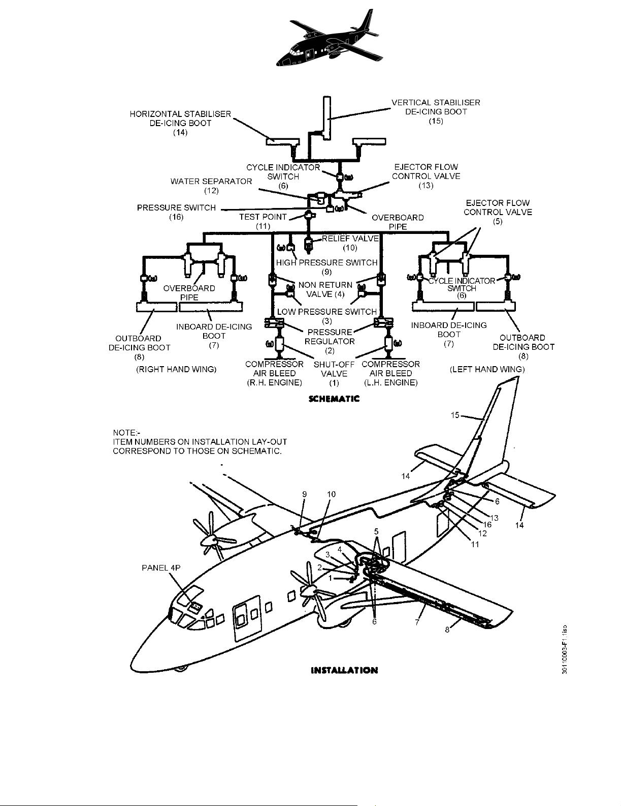
(1) Shut-Off Valves
The 'open' - 'closed' indication of the Shut-Off Valves is signalled via an integral set of
microswitches which operate in response to the solenoid valve movement.
Position indication is afforded by indicator modules on panel 4P (immediately above
control switches).
(2) Cycling
Cycle indicator switches, sited downstream of each ejector valve connect a supply to the
appropriate indicator light (green) on panel 4P when the related boot/s are on the
inflation phase of a cycle.
(3) High/Low Pressure Warning (System)
(a) High Pressure Warning
A H.P. switch is sited upstream of the relief valve and will make a supply available
(e.g. in the event of a failed pressure regulator) to the bleed air DUCT PRESSure
light on panel 4P should the system pressure exceed 24 p.s.i; attention is drawn by
the simultaneous illumination of the BLEED air module on the centralized warning
panel.
(b) Low Pressure Warning
A L.P. switch is introduced immediately downstream of the pressure regulator in
each engines delivery line. Should either switch 'make' (e.g. as a result of a burst
pipe) a supply will be made available to the bleed air DUCT PRESSure light on
panel 4P; attention is drawn by the simultaneous illumination of the BLEED air
module on the centralized warning panel.
NOTE: Circuits for both warning systems are wired in series with engine oil pressure
relays such that warning is only afforded when engines are running.
(4) Pressure Warning and Time Delay
A pressure switch is located between the ejector flow control valve and the water
separator. The switch is set to illuminate an amber SYS Pressure caution light on panel
4P, on a falling de-icing boot inflation pressure of 11.5 psig. The A/ICE PANEL (BLEED
on early aircraft) module on the centralized warning panel is also illuminated. The
caution light will extinguish on a rising inflation pressure of 13.5 psig.
NOTE: The pressure switch only functions when the aircraft is in the air i.e. it is inhibited
when the weight switches are operational.
Apr 24/03
30-11-00 Page 3
EFFECTIVITY: All
z
SD3-60 AIRCRAFT MAINTENANCE MANUAL
Aerofoil De-icing
Figure 1
Apr 24/03
30-11-00 Page 4
EFFECTIVITY: All
zSD3-60 AIRCRAFT MAINTENANCE MANUAL
A time delay relay routes the pressure switch output to the SYS P indication, and is set to
approximately 60 seconds to avoid any nuisance warnings during the landing flare,
where lower boot inflation pressures would be expected.
(5) Spar Box Overheat Warning
This facility is shared with the air conditioning system. Refer to 21-00-00, pb1.
2. Operation
A. General
The system operates in the dormant or de-icing role as respectively described in B and C.
B. Dormant Function
With engines running and the controls on panel 4P set thus:-
the five ejector valves will constantly operate in the jet pump mode to keep the boots sucked
flat to their respective leading edges.
C. De-icing Function
With engines running and the controls on panel 4P set thus:-
the boots will commence and repeat flexing (inflation/deflation) in the sequence inner wings -
outer wings - tail.
During inflation, for either one minute or three minute cycles, the inner wing ejector valves are
energised for 5 seconds and then simultaneously de-energised with the energising of the
outer wing ejector for 5 seconds, followed by the energising of the tail ejector valve for 5
seconds.
This is followed by a dwell period of 45 seconds or 165 seconds (depending on the cycle
duration).
The cycle is repeated as long as the timer is switched ON. If the timer is switched OFF at any
time the timer will complete the cycle and return to the starting position. Momentary operation
of the control switch provides one operational cycle of the de-icer boots.
During the period of de-energisation of each ejector valve, air is removed from the related
boot/s by the valve's jet pump action.
WINGS & TAIL BLEED air control switches : NORMal
TIMER : OFF
WINGS & TAIL BLEED air control switches : NORMal
TIMER : 1 MINute/3 MINute
Jun 30/01
30-11-00 Page 201
EFFECTIVITY: All
z
SD3-60 AIRCRAFT MAINTENANCE MANUAL
AMM30-11-00 4.0.0.0 AEROFOIL DE-ICING - MAINTENANCE PRACTICES
1. Adjustment/Test
A. Function the system
(1) Start engines
(2) Check that C/B Nos. 94 and 244 on respective distribution panels 1D and 2D are closed.
(3) On panel 4P perform the following:-
(a) Check that WINGS & TAIL BLEED air control switches are set to NORMal.
(b) Set TIMER switch to 1 MINute cycle.
(4) With reference to appropriate indicator lights, check that the ejector flow control valves
are energised in the following order and for the period specified.
(a) INNER wing (left and right) - 5 seconds
(b) OUTER wing (left and right) - 5 seconds
(c) TAIL boots - 5 seconds, followed by a 45 second dwell period to complete the cycle,
which will then repeat itself until the TIMER is switched OFF.
(5) Set TIMER switch to 3 MINute cycle and repeat operation (4), checking that there is a
165 second dwell period to complete the cycle.
(6) Switch TIMER - OFF.
(7) Select left WINGS & TAIL BLEED air control switch to SHUT and TIMER switch to 1
MINute cycle, and repeat operation (4).
(8) Return left control switch to NORMal and select right control switch to SHUT repeating
operation (4).
(9) Return right control switch to NORMal and switch timer - OFF.
(10) Check that all cycling indication lights are extinguished.
(11) Shut down engines.
Jun 30/01
30-11-01 Page 201
EFFECTIVITY: All
z
SD3-60 AIRCRAFT MAINTENANCE MANUAL
AMM30-11-01 5.0.0.0CHECK VALVES (ENGINE AIR BLEED LINES) - MAINTENANCE PRACTICES
1. Adjustment/Test
NOTE: For convenience of maintenance, the testing of the high pressure switch and relief valve
are carried out in the same procedure.
A. Function check the valves
Special tools and equipment:
Regulated air pressure supply (0-100 p.s.i.)
(1) Close C/B Nos. 94 and 244 on respective distribution panels 1D and 2D. Select the
TIMER switch OFF.
CAUTION: PLACARD THE TIMER SWITCH TO ENSURE THAT IT IS NOT SELECTED ON
DURING HIGH PRESSURE TESTS.
(2) Refer 6-30-00, pb1. Remove the following panels:-
(3) Disconnect de-icing pipes from bleed points on engines and blank off engine
connections.
(4) Connect regulated air pressure supply to test point and raise pressure slowly to 20 p.s.i.
maintaining flow to compensate for loss through ejector valves.
(5) Check that little or no leakage emits from the disconnected piping at the engines,
indicating that the check valves are functional.
NOTE: The label at the test point, restricting pressure to 20 p.s.i. is to be ignored when
performing the following test - the restriction only applies if boots are cycle
functioned from an external supply (engines stopped).
(6) Increase the pneumatic pressure slowly through 20 p.s.i. checking that:-
(a) the relief valve (accessed via panel 314 MZ) discharges air on a rising pressure of
20 ± 1 p.s.i.
420 AT
510 AT
312 TZ (rear baggage compartment aft bulkhead)
Jun 30/01
30-11-01 Page 202
EFFECTIVITY: All
zSD3-60 AIRCRAFT MAINTENANCE MANUAL
(b) a continuing increase in pressure (to compensate for relief valve loss) will cause the
high pressure switch to illuminate the DUCT PRESSure light on panel 4P. before
reaching 24 p.s.i.
NOTE: Check that on a falling pressure of 22 p.s.i. the high pressure switch 'breaks',
extinguishing the DUCT PRESSure light.
(7) Reduce pressure to 20 p.s.i. and check that relief valve has reset.
(8) Reduce pressure to zero and disconnect air pressure supply.
(9) Remove blanks from P2.5 engine connections and re-connect associated piping.
(10) Close access panels.
(11) Remove placards and close C/B Nos. 94 and 244.
Jun 30/01
30-11-06 Page 201
EFFECTIVITY: All
z
SD3-60 AIRCRAFT MAINTENANCE MANUAL
AMM30-11-06 6.0.0.0RELIEF VALVE - MAINTENANCE PRACTICES
1. Adjustment/Test
A. Function check the relief valve.
For convenience of maintenance, the relief valve is functioned during check valves (engine
air bleed lines) test. Refer to 30-11-01, pb201.
Jun 30/01
30-11-11 Page 201
EFFECTIVITY: All
z
SD3-60 AIRCRAFT MAINTENANCE MANUAL
AMM30-11-11 7.0.0.0LOW PRESSURE SWITCHES - MAINTENANCE PRACTICES
1. Adjustment/Test
A. Function check the pressure switches
Special tools and equipment:
Regulated air pressure supply.
(1) Refer to 12-09-03, pb301. Provide electrical power.
(2) Check that C/B Nos 94 and 244 on respective distribution panels 1D and 2D are closed.
(3) Obtain access to both engines by removing panel 410AL.
(4) Disconnect de-icing pipes from interstage P2.5 bleed point on engines and blank off
engine connections.
(5) Gain access at panels 510TT or 510BB (left) and 610TT or 610BB (right) and disconnect
piping from outlet side of the check valves. Blank off piping and valves.
(6) Check left pressure switch as follows:-
(a) Select left BLEED air switch to NORMal.
(b) Open C/B No. 16 on distribution panel 1D (de-energising the left engine oil pressure
relay thus permitting the bleed air - DUCT PRESSure light on panel 4P to illuminate
under the influence of the left duct pressure switch, with engine stopped).
(c) Connect regulated air pressure supply to the previously disconnected piping at the
engine P2.5 bleed point.
(d) Raise pressure slowly, checking that the warning light is extinguished when the
pressure reaches 6 p.s.i. Reduce pressure slowly and check that the light
illuminates at 5 ± 0.25 p.s.i.
(e) Reduce pressure to zero and disconnect air pressure supply.
(f) Close C/B No. 16.
(g) Select left BLEED air switch to SHUT.
(7) Check right pressure switch as follows:-
(a) Select right BLEED air switch to NORMal.