Rolladen-Schneider LS8-s Technical specifications

DG Flugzeugbau GmbH
Otto-Lilienthal-Weg 2 / Am Flugplatz •• D-76646 Bruchsal •• Germany
Postfach 1480, D-76604 Bruchsal •• Germany
Spareparts and Materials: Tel. +49 (0) 7251/3020-270 •• eMail: [email protected]
http://www.dg-flugzeugbau.de
FLIGHT MANUAL
FOR THE
SAILPLANES
LS8-s AND LS8-sb
Type: LS8-a
Versions: LS8-s
LS8-sb
TCDS No.: EASA TCDS No. A.047
Serial-No.: __________________________
Registration Signs: __________________________
Edition: April 2005
Pages marked “EASA-approved“ are approved by:
(Signature)
(Authority)
(Stamp)
(Date of Approval) 19.August 2005
This sailplane is to be operated in compliance with information and
limitations contained herein.
Warnings
•Each sailplane is a highly complex unit. It may threaten your health or
endanger your life, when being used improperly or outside its approved
operating range or being maintained improperly.
•Before using the plane, study all manuals thoroughly. Especially take note of
warnings, cautions and notes provided.
•Never fly without a thorough pre-flight check according to the Flight
Manual!
•Always stay within safety altitudes.
•Always make sure to be able to perform a safe out landing.
•Respect stall speeds. Always use a safety margin above the stall speed
related to the flight condition, especially at low altitudes and in the
mountains.
•Only use battery chargers specified in the Manual.
•Do not work on control systems apart from lubrication.
•Maintenance and repairs should only be accomplished by the manufacturer
or at certified repair stations rated for these types of work. A list of stations
with experience at LS aircraft may be obtained from DG Flugzeugbau.
•Even if no annual inspections are required in your country, have your aircraft
checked annually, see Maintenance Manual chapter 2
.
•Please pay attention to our web-site www.dg-flugzeugbau.de. There you will
find the latest technical notes and service information for your glider:
www.dg-flugzeugbau.de/tech-mitteilungen-e. The „DG Pilot Info“ informs
you immediately by e-mail about the publication of new technical notes and
service information. If you don’t receive this info service, please send a mail
receive this service free of charge.

Flight Manual LS8-s and LS8-sb Contents
Edition: April 2005 0.1
0 MANUAL CONTENTS
0.1 Log of Revisions
Any revision of the present manual, except actual weighing data, must be
recorded in the following table and in case of approved Sections endorsed by the
responsible airworthiness authority.
The new or amended text in the revised page will be indicated by a black vertical
line on the right margin, and the revision No. and the date will be shown on the
bottom left hand of the page
Revision No. Chapter Pages Date of Issue Approval
Signature
Date of EASA
Approval
Flight Manual LS8-s and LS8-sb Contents
Edition: April 2005 0.2
0.2 List of Effective Pages
Chapter Page Edition Edition Edition Edition
0 Titel page April 2005
Warnings April 2005
0-1 April 2005
0-2 April 2005
0-3 April 2005
0-4 April 2005
0-5 April 2005
0-6 April 2005
1 1-1 April 2005
1-2 April 2005
1-3 April 2005
1-4 April 2005
1-5 April 2005
2 2-1 April 2005
2-2 April 2005
2-3 April 2005
2-4 April 2005
2-5 April 2005
2-6 April 2005
2-7 April 2005
2-8 April 2005
2-9 April 2005
2-10 April 2005
2-11 April 2005
2-12 April 2005

Flight Manual LS8-s and LS8-sb Contents
Edition: April 2005 0.3
0.2 List of Effective Pages continued
Chapter Page Edition Edition Edition Edition
3 3-1 April 2005
3-2 April 2005
3-3 April 2005
3-4 April 2005
3-5 April 2005
3-6 April 2005
3-7 April 2005
3-8 April 2005
3-9 April 2005
3-10 April 2005
3-11 April 2005
3-12 April 2005
3-13 April 2005
4-1 April 2005
4-2 April 2005
4-3 April 2005
4-4 April 2005
4-5 April 2005
4-6 April 2005
4-7 April 2005
4-8 April 2005
4-9 April 2005
4-10 April 2005
4-11 April 2005
4-12 April 2005
4-13 April 2005
4-14 April 2005
4-15 April 2005
4-16 April 2005
4-17 April 2005
4-18 April 2005
4-19 April 2005
4-20 April 2005
Flight Manual LS8-s and LS8-sb Contents
Edition: April 2005 0.4
0.2 List of Effective Pages continued
Chapter Page Edition Edition Edition Edition
4 4-21 April 2005
4-22 April 2005
4-23 April 2005
4-24 April 2005
4-25 April 2005
4-26 April 2005
4-27 April 2005
4-28 April 2005
4-29 April 2005
4-30 April 2005
4-31 April 2005
4-32 April 2005
4-33 April 2005
4-34 April 2005
5 5-1 April 2005
5-2 April 2005
5-3 April 2005
5-4 April 2005
5-5 April 2005
5-6 April 2005
6 6-1 April 2005
6-2 April 2005
6-3 April 2005
6-4 April 2005
6-5 April 2005

Flight Manual LS8-s and LS8-sb Contents
Edition: April 2005 0.5
0.2 List of Effective Pages continued
Chapter Page Edition Edition Edition Edition
7 7-1 April 2005
7-2 April 2005
7-3 April 2005
7-4 April 2005
7-5 April 2005
7-6 April 2005
7-7 April 2005
7-8 April 2005
7-9 April 2005
7-10 April 2005
7-11 April 2005
7-12 April 2005
7-13 April 2005
7-14 April 2005
8 8-1 April 2005
8-2 April 2005
8-3 April 2005
8-4 April 2005
8-5 April 2005
8-6 April 2005
8-7 April 2005
8-8 April 2005
8-9 April 2005
8-10 April 2005
8-11 April 2005
9 9-1 April 2005
9-2 April 2005
9-3 April 2005
9-4 April 2005
9-5 April 2005
9-6 April 2005
Flight Manual LS8-s and LS8-sb Contents
Edition: April 2005 0.6
0.3 TABLE OF CONTENTS
Section Chapter Approval Status
1 General........................................................................... not approved
2 Limitations ............................................................................ approved
3 Emergency Procedures ........................................................ approved
4 Normal Procedures .............................................................. approved
5 Performance ................................................................partly approved
6 Weight and Balance ....................................................... not approved
7Description of Systems ................................................... not approved
8 Handling, Servicing and Maintenance ........................... not approved
9 Supplements.................................................................... not approved

Flight Manual LS8-s and LS8-sb General
Edition: April 2005 1-1
1 General
Contents of Chapter 1: Page
1 General....................................................................... 1-1
1.1 Introduction ............................................................. 1-2
1.2 Certification Basis..................................................... 1-2
1.3 Warnings, Caution and Notes (Definitions) ............... 1-3
1.4 Descriptive and Technic al Data ................................. 1-4
1.5 Three View Drawing ................................................. 1-5
Flight Manual LS8-s and LS8-sb General
Edition: April 2005 1-2
1.1 INTRODUCTION
This sailplane Flight Manual has been prepared to provide pilots and
instructors with information for the safe and efficient operation of the
LS 8-s and LS8-sb sailplanes.
This manual includes the material required to be furnished to the pilot by
JAR Part 22. It also contains supplementary data supplied by the sailplane
manufacturer.
The LS8-s or LS8-sb is a high performance sailplane, not a basic trainer.
However excellent its design, construction, performance and handling
qualities, flying it requires a skilled pilot, who observes the limitations and
recommendations set out in this manual.
1.2 CERTIFICATION BASIS
These sailplanes with the type designation LS8-s or LS8-sb have been
approved by EASA in accordance with JAR-22 dated 28. October 1985,
(Change 5).
The EASA-Type Certificate No. A.047 for LS 8-s and LS8-sb has been
issued on 19.August 2005.
Category of Airworthiness: "Utility".

Flight Manual LS8-s and LS8-sb General
Edition: April 2005 1-3
1.3 WARNINGS,CAUTIONS AND NOTES (Definitions)
The following definitions apply to warnings, cautions and notes used in the
Flight Manual
Warning: Means that the non-observation of the corresponding
procedure leads to an immediate or important
degradation of the flight safety.
Caution: Means that the non-observation of the corresponding
procedure leads to a minor or to a more or less long
term degradation of the flight safety.
Note: Draws the attention to any special item not directly related to
safety, but which is important or unusual.
Flight Manual LS8-s and LS8-sb General
Edition: April 2005 1-4
1.4 DESCRIPTIVE AND TECHNICAL DATA
The LS 8-s and LS8-sb are single-seater sailplanes with carbon fibre wing
shell, winglets, T-tail, wing and vertical tail fin water ballast systems,
retractable and sprung landing gear, and upper wing surface air brakes.
They may be operated in 15m or 18m span and winglets in both versions.
The fuselage structure of LS8-s and LS8-sb is different, because the
LS8-sb is prepared for later engine installation. Otherwise both planes are
structurally identical.
These sailplanes have been produced using the latest technology of
industrial fibre design (Glass-, Aramid- and Carbon fibres).
Models LS8-s and LS8-sb are designed for competition flights – high
performance combined with excellent handling characteristics.
Wing span 15 m 49,2 ft 18 m 59,6 ft
Length 6,74 m 22,11 ft 6,74 m 22,11 ft
Height 1,33 m 4,36 ft 1,33 m 4,36 ft
MAC 0,700 m 2,30 ft 0,634 m 2,08 ft
Wing Area 10,5 m² 113,0 sq. ft 11,40 m² 122,9 sq. ft
Wing aspect ratio 21,43 21,43 28,38 28,38
Maximum gross weight 525 kg 1157 lbs 575 kg 1267 lbs
Max. wing loading 50 kg/m² 10,2 lbs/sq. ft 50,4 kg/m² 10,3 lb/sq. ft

Flight Manual LS8-s and LS8-sb General
Edition: April 2005 1-5
1.5 THREE VIEW DRAWING
Flight Manual LS8-s and LS8-sb Limitations
Edition: April 2005 EASA appr. 2-1
2 LIMITATIONS
Contents of Chapter 2:
2 Limitations ................................................................. 2-1
2.1 Introduction ............................................................ 2-2
2.2 Airspeeds (IAS) ...................................................... 2-3
2.3 Airspeed Indicator colour markings .......................... 2-4
2.4 Mass (Weight) ......................................................... 2-5
2.5 Centre of gravity limits ............................................. 2-6
2.6 Approved manoeuvres ............................................. 2-7
2.7 Manoeuvring load factors ........................................ 2-7
2.8 Kinds of operation ................................................... 2-8
2.9 Flight crew .............................................................. 2-9
2.10 Minimum equipment .............................................. 2-10
2.11 Aero tow, winch- and auto tow launching ............... 2-11
2.12 Other limitations .................................................... 2-12
2.12.1 Operating placards for limitations ........................ 2-12

Flight Manual LS8-s and LS8-sb Limitations
Edition: April 2005 EASA appr. 2-2
2.1 INTRODUCTION
Section 2 includes operating limitations, instrument markings and basic
placards necessary for safe operation of the LS8-s and LS8-sb sailplanes,
their standard systems and standard equipment.
The limitations included in this section have been approved by EASA.
The LS 8-s and LS8-sb sailplanes have been designed and approved
according to JAR 22 requirements. Factors of safety (relation of ultimate
loads to permissible maximum loads occurring during operation) are 1.5
only. Thus, ultimate loads will be reached, when exceeding permissible load
factors by 50%. When exceeding permissible speeds, the safety reserve is
much lower.
Maximum loads should never be caused by the pilots control surface
deflections – they result from severe turbulence and the necessary control
surface deflections to retain the desired flight attitude. Severe turbulence
according to airworthiness requirements includes wave rotors,
cumulonimbus clouds, dust devils and turbulence when crossing mountain
ridges in strong winds.
Warning: Therefore, operational limits, - speeds and load factors - must be
adhered to !
Flight Manual LS8-s and LS8-sb Limitations
Edition: April 2005 EASA appr. 2-3
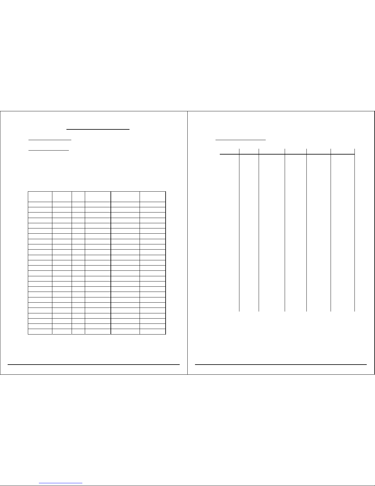
2.2 AIRSPEEDS (IAS)
Maximum permissible
speed
IAS
km/h Kt MPH
Remarks
VNE
Never exceed speed in
calm air and up to an
altitude above MSL of:
2000 m (6500 ft) 280 151 174
Do not exceed this speed in any
operation and do not use more than 1/3
of control deflection.
3000 m (9800 ft) 266 144 165
4000 m (13100 ft) 253 137 157
6000 m (19700 ft) 227 122 141
8000 m (26200 ft) 202 109 126
10000 m (32800 ft) 179 97 111
12000 m (39400 ft) 156 84 97
VRA Rough air speed 195 105 121
Do not exceed this speed except in calm
air and then only with caution.
Examples of rough air are lee wave
rotor, thunderclouds, dust devils and
turbulence when crossing mountain
ridges in strong winds.
VA Manoeuvring speed 195 105 121
Do not make full or abrupt control
movement above this speed, because
under certain conditions the sailplane
may be overstressed by full control
movement.
VW Maximum winch- launching
speed
140 76 87 Do not exceed this speed during winch-
or auto-tow launching.
VT Maximum aero towing
speed
195 105 121 Do not exceed this speed during aero
towing.
VL0 280 151 174
Maximum landing gear
operating speed
Do not extend or retract the landing gear
above this speed.
Maximum air brake
extension speed
280 151 174

Flight Manual LS8-s and LS8-sb Limitations
Edition: April 2005 EASA appr. 2-4
2.3 AIR SPEED INDICATOR COLOUR MARKINGS
Airspeed indicator markings and their colour-code significance are shown
below.
Marking (IAS) range or
value
Significance
Green arc 97-195 km/h
52-105 Kt
60-121 MPH
Normal operating range
(Air brakes retracted)
Yellow arc 195-280 km/h
105-151 Kt
121-174 MPH
Manoeuvres must be conducted with caution
and only in smooth air.
Red line 280 km/h
151 Kt
174 MPH
Maximum speed for all not restricted operations
Yellow
triangle
95 km/h
51 Kt
59 MPH
Recommended minimum approach speed at
maximum weight without water ballast
For an example of airspeed indicator colour marking see Maintenance Manual
chapter 8.
Flight Manual LS8-s and LS8-sb Limitations
Edition: April 2005 EASA appr. 2-5
2.4 MASS (WEIGHT)
Maximum take-off masses
Maximum take-off mass (15m wing span) .................... 525 kg <1157 lbs>
Maximum take-off mass (18m wing span) .................... 575 kg <1267 lbs>
Important Note:When landing on airfields, water ballast should
preferably be dumped. Before outlandings, water
ballast must always be dumped. Pilots are advised
against landing with maximum all-up mass.
LS8-s: Maximum weight of non-lifting parts ......... 255 - 263 kg <562 – 580 lbs>
LS8-sb: Maximum weight of non-lifting parts ......... 280 - 288 kg <617 – 635 lbs>
Value must be determined according to table in Maintenance Manual, chapter 5,
related to empty mass and empty mass C.G. position. The term “non-lifting”
parts includes the following:
•Fuselage (with permanently installed equipment, canopy, and main pins)
•Cockpit load (Pilot + parachute + equipment <for instance tail fin battery
in baggage compartment instead of in tail fin>)
•Horizontal tail
Tail fin water ballast and tail fin battery in tail fin do not count for “non-lifting”
parts, but for maximum all-up weight.
continued next page

Flight Manual LS8-s and LS8-sb Limitations
Edition: April 2005 EASA appr. 2-6
2.6 MASS (WEIGHT)(continued)
Water ballast in wings
(depending on loading conditions)..........................max. 190 kg <419 lbs>
Warning: Wing water ballast must always be compensated by tail fin
water ballast according to table 4.7.10.5 .
Tail fin water ballast (depending on wing water ballast)
LS8-s with integral tail fin tank ........................... max. 12 kg <26,5 lbs>
LS8-sb with integral tail fin tank ............................. max. 7,5 kg <16,5 lbs>
Note: Due to production tolerances, the tail fin tank can take
some more water. Therefore the actually filled amount
of water must be positively checked!
Maximum mass in Baggage Compartment: ............ max. 5.0 kg <11 lbs>
Maximum mass of all instrument panel installations
..... max. 6.7 kg <14.8 lbs>
Warning: The vertical tail fin battery may be removed from the tail fin to
reduce Minimum Cockpit Load (See entries section 6.2 for
possible combinations !)
Flight Manual LS8-s and LS8-sb Limitations
Edition: April 2005 EASA appr. 2-7
LS8-s / LS8-sb Inflight C.G. position
300
350
400
450
500
550
600
260 280 300 320 340 360 380 400 420
Inflight C.G. position [mm aft of Datum]
All-up Weight [kg]
15m
18m
1
3
2
4
567
2.5 CENTRE OF GRAVITY LIMITS
Datum Point: Leading edge of wing at root, when under side of fuselage boom
is placed horizontal.
Maximum allowable forward C.G.
at maximum mass: 280 mm <11.024 in> aft of Datum
Maximum allowable rearward
C.G. position: 400 mm <15.748 in> aft of Datum
Warnung: Vertical tail fin water ballast MUST be used to compensate
C.G. displacement due to wing water ballast, surplus may be
used to compensate pilot weight above Minimum Cockpit Load
!
Maximum amounts see “Normal procedures” sections 4.7.10.4
and 4.7.10.5/6.

Flight Manual LS8-s and LS8-sb Limitations
Edition: April 2005 EASA appr. 2-8
2.6 APPROVED MANOEUVRES /CATEGORY OF AIRWORTHINESS
The sailplanes LS8-s and LS8-sb are approved for normal soaring flight
(category "Utility") .
Aerobatic flight not approved.
2.7 MANOEUVRING LOAD FACTORS
At 195 km/h <105 Kt, 121 MPH> .................... +5.3 g to -2.65 g
At 280 km/h <151 Kt, 174 MPH>
(air brakes retracted) ........................ +4.0 g to -1.5 g
At 280 km/h <151 Kt, 174 MPH>
(air brakes extended) ........................ +3.5 g to -0.0 g
2.8 KINDS OF OPERATION
a) With water ballast: - Day-VFR-Flight
- Aero tow
- Winch- and auto tow launch
Use of water ballast limited to temperatures above +5°C <41°F>
Additives to water ballast not approved!
b) Only without water ballast:
- Cloud flying (during day), when required
equipment is installed (see section 2.10)
For USA only:
Night-VFR, IFR and Flight into known icing conditions are not approved.
Flight Manual LS8-s and LS8-sb Limitations
Edition: April 2005 EASA appr. 2-9
2.9 FLIGHT CREW
Maximum cockpit load
(Pilot + parachute + baggage + temporary equipment, batteries in
baggage compartment [The tail fin battery installed in the tail does not
count for cockpit load; it counts, when the tail battery is installed in the
baggage compartment for trim reason]
trim weights)
................................................................max. 110 kg <242 lbs>
See entries in chapter 6
Oxygen equipment see section 7.13
Minimum cockpit load (Pilot + parachute)
see Cockpit placarding & entries in chapter 6
Guiding values for modification of Minimum Cockpit Load:
Installation of 1 front trim ballast weight 2.5 kg <5.5 lbs> decreases Cockpit
Load by 5 kg <11 lbs>. (max. 3 front trim weights can be installed).
Further data regarding Cockpit Load see chapter 6.
Warning: Guiding values for modification of Minimum Cockpit Load
always refer to conditions of last C.G. weighing. These
conditions can be taken from entries in chapter 6.
Warning: For reasons of safety, the cockpit placarded Minimum Cockpit
Load in large digits includes the full tail fin tank ballast and
tail fin battery weights.
Lighter pilots must positively check the following:
a) Tail tank empty: with discharge lever in “OPEN” position
the valve is really open (with discharge lever opened, air
can be blown through valve using tail tank adaptor)
b) Tail battery not installed:
(Check with elevator removed)
For possible combinations see entries section 6.2.

Flight Manual LS8-s and LS8-sb Limitations
Edition: April 2005 EASA appr. 2-10
2.10 MINIMUM EQUIPMENT
•Airspeed Indicator: scale 50-300 km/h <27-162 Kt.; 31-186 MPH>
Colour marking see chapter “Limitations” 2.3
Approved types and example of colour marking see
Master Equipment List in Maintenance Manual chapter 6.
Pressure pick-ups see section 7.9.
•Altimeter: scale in m or ft.
Pressure pick-ups see section 7.9.
When an altimeter of up to 20000 ft only is being used, a placard
must be near the altimeter stating: Maximum flying altitude 20000 ft.
•Thermometer: Types and position of temperature pick-up see Maintenance
Manual.
•Four piece seat belt harness: approved types see Master Equipment List in
Maintenance Manual.
•Vertical tail filling tube adaptor: for checking of tail fin tank valve function.
•Back cushion or parachute, in compressed form not thinner than 5 cm <2 in>.
•Checklist, Type placard, Data and Loading placard, Operating placards
•Operational VHF radio system, depending on national legislation requirements
•Flight Manual LS8-s / LS8-sb
Additionally for cloud flying:
•Airspeed Indicator:
recommended: scale 50-300 km/h with maximum 1 turn only
<27-162 Kt.; 30-186 MPH>
•Turn and bank indicator
•Compass, compensated
•Variometer: recommended: range at least ±10 m/s <2000 ft/min; 20 Kt.>
•Additionally ATC equipment, for instance VHF-radio and transponder, are
recommended.
Manufacturer approved instruments and radios are listed in Maintenance Manual
chapter 6 (Master Equipment List).
Flight Manual LS8-s and LS8-sb Limitations
Edition: April 2005 EASA appr. 2-11
2.11 AERO TOW,WINCH-LAUNCH AND AUTO-TOW
2.11.1 Maximum approved tow speeds
Maximum approved winch-launch speed:.........140 km/h <76 Kt.; 87 MPH>
(also valid for Auto-tow launch)
Maximum approved aero tow speed:........... 195 km/h <105 Kt.; 121 MPH>
2.11.2 Weak Links
For Winch launch.............max. 8250 Newton <825 kg, 1819 lbs>
Recommended: Tost weak link No. 3, colour code red,
......................................rated break away load 7500 ±750N
................................................ <750 ±75 kg; 1653 ±165 lbs>
For Aero tow ....................max. 6600 Newton <660 kg, 1455 lbs>
Recommended: Tost weak link No. 5, colour code blue,
...................rated break away load 6000 ±600N
...................................................<600 ±60 kg; 1323 ±132 lbs>
Minimum tow cable length for aero tow.................. 30 m <100 ft>
recommended length......... up to 80 m <260 ft>
Important Note: During motor glider tow, limitations regarding weak
link and tow cable length must be complied with (See
Manual of towing motor glider).

Flight Manual LS8-s and LS8-sb Limitations
Edition: April 2005 EASA appr. 2-12
2.12 Further Limitations
2.12.1 OPERATING PLACARDS FOR LIMITATIONS
2.12.1.1 LS8-s
DG-Flugzeugbau GmbH M I N I M U M C O C K P I T L O A D:___ kg / lbs
Type: LS8-s Serial No.:_______ Minimum Cockpit Load with empty tail tank: ___ kg / lbs
Data Placard Valid for equipment configuration according
Airspeed Limits: km/h Kt MPH. to Flight Manual chapter 6.
Winch launch/Auto tow 140 76 87 Under instrument panel cover
Aero tow 195 105 121
In rough air 195 105 121 Maximum baggage weight 5kg <11 lbs>
Never exceed (VNE) 280 151 174 (Soft items only)
m ft kg lbs At baggage compartment
Max. Take-off Mass *) 15 42 525 1157
with 5“-wheel: 18 59 575 1267
*) including water ballast
Aerobatic manoeuvres not approved Altitude related VNE speeds above MSL
Weight Limitations M ft km/h Kt MPH
Maximum Cockpit Load ....max.______kg/lbs Up to 2000 ( 6500) - 280 151 174
Minimum Cockpit Load min. ______kg/lbs Up to 3000 ( 9800) - 266 144 165
Minimum Cockpit Load with Up to 4000 (13100) - 253 137 157
empty tail tank Up to 6000 (19700) - 227 122 141
and without tail battery min.:______kg/lbs Up to 8000 (26200) - 202 109 126
Valid for equipment configuration according Up to 10000 (32800) - 179 97 111
to Flight Manual chapter 6. Up to 12000 (39400) - 156 84 97
Lighter pilots must compensate lack of weight Near airspeed indicator unless marked internally
2.12.1.1 LS8-sb
DG-Flugzeugbau GmbH M I N I M U M C O C K P I T L O A D:___ kg / lbs
Type: LS8-sb Serial No.:_______ Minimum Cockpit Load with empty tail tank: ___ kg / lbs
Data Placard Valid for equipment configuration according
Airspeed Limits: km/h Kt MPH. to Flight Manual chapter 6.
Winch launch/Auto tow 140 76 87 Under instrument panel cover
Aero tow 195 105 121
In rough air 195 105 121 Maximum baggage weight 5kg <11 lbs>
Never exceed (VNE) 280 151 174 (Soft items only)
m ft kg lbs At baggage compartment
Max. Take-off Mass *) 15 42 525 1157
18 59 575 1267
*) including water ballast
Aerobatic manoeuvres not approved Altitude related VNE speeds above MSL
Weight Limitations M ft km/h Kt MPH
Maximum Cockpit Load ....max.______kg/lbs Up to 2000 ( 6500) - 280 151 174
Minimum Cockpit Load min. ______kg/lbs Up to 3000 ( 9800) - 266 144 165
Minimum Cockpit Load with Up to 4000 (13100) - 253 137 157
empty tail tank Up to 6000 (19700) - 227 122 141
and without tail battery min.:______kg/lbs Up to 8000 (26200) - 202 109 126
Valid for equipment configuration according Up to 10000 (32800) - 179 97 111
to Flight Manual chapter 6. Up to 12000 (39400) - 156 84 97
Lighter pilots must compensate lack of weight Near airspeed indicator Unless marked internally
Flight Manual LS8-s and LS8-sb Emergency Procedures
Edition: April 2005 EASA appr. 3-1
3 EMERGENCY PROCEDURES
Contents of Chapter 3:
3 Emergency Procedures ........................................................ 3-1
3.1 Introduction ..................................................................... 3-2
3.2 Emergency canopy jettison ............................................... 3-3
3.3 Emergency exit ................................................................. 3-4
3.4 Stall recovery ................................................................... 3-5
3.5 Spin recovery ................................................................... 3-6
3.6 Spiral dive recovery .......................................................... 3-7
3.7 Other emergencies ............................................................ 3-8
3.7.1 Limitation of high speed flight.................................. 3-8
3.7.2 Rain ...................................................................... 3-9
3.7.3 Inadvertent freezing / icing ...................................... 3-10
3.7.4 Flight with asymmetric water ballast loading ............. 3-11
3.7.5 Winch launch cable failure ...................................... 3-11
3.7.6 Emergency landing with landing gear retracted ......... 3-12
3.7.7 Ground loop........................................................... 3-12
3.7.8 Emergency landing in water .................................... 3-13
3.7.9 Flight in the vicinity of thunder storms ..................... 3-13

Flight Manual LS8-s and LS8-sb Emergency Procedures
Edition: April 2005 EASA appr. 3-2
3.1 INTRODUCTION
Section 3 provides checklist and amplified procedures for coping with
emergencies that may occur.
Flight Manual LS8-s and LS8-sb Emergency Procedures
Edition: April 2005 EASA appr. 3-3
3.2 EMERGENCY CANOPY JETISSON
Canopy locks : pull both red handles to stops
- Right handle operates emergency canopy
jettison, therefore longer travel as left handle.
- Hand force increases for emergency jettison
travel to avoid unintentional jettison during
normal operation.
Canopy : push off at both red handles
- the lifting instrument panel assists pushing off.
- spring loaded peg at canopy frame rear edge
acts as temporary hinge for clean separation
from fuselage.

Flight Manual LS8-s and LS8-sb Emergency Procedures
Edition: April 2005 EASA appr. 3-4
3.3 EMERGENCY EXIT
Canopy - jetisson
Seat harness - open
Exit - Lift with arms over cockpit rim and
push yourself away from the sailplane
- preferably dive under wing, to avoid the tail
Flight Manual LS8-s and LS8-sb Emergency Procedures
Edition: April 2005 EASA appr. 3-5
3.4 STALL RECOVERY
Warning - slight tail shudder prior to entry
- aileron effectiveness reduced by about 50%
- sink rate increases considerably
Termination - Stick forward to neutral until normal flight speed
is achieved.
Stalling speeds: see section 5.2.2
Caution: When during stalled flight the angle of attack is
increased considerably by further “pulling”, then –
depending on C.G. position- spinning may result from
asymmetric stall.
To avoid unintentinal spinning, the plane should
never be stalled. Fly with enough speed reserve in
rough air and especially in final approach to landing.

Flight Manual LS8-s and LS8-sb Emergency Procedures
Edition: April 2005 EASA appr. 3-6
3.5 SPIN RECOVERY
Simultaneously:
Elevator - push forward
Rudder - full rudder deflection opposite to spin rotation
Aileron - neutral or opposite to spin rotation for quicker
termination
Until rotation stops, then:
Elevator - smooth but swift pull-out
Altitude loss during recovery:
about 100-150 m <300-450 ft>
Recovery speed up to 195 km/h <105 Kt., 121 MPH>
Note: According to actual aileron deflection and C.G. position, more or
less pronounced floating around the pitch axis (pitching oscillation)
occurs during spinning.
Warning: During dive-out be alert not to exceed maximum permissible
speed VNE = 280 km/h <151 Kt.; 174 MPH> inadvertently, see
also chapter “Limitations”, section 2.2!
Warning: Intentional spinning with full water ballast is prohibited!
Flight Manual LS8-s and LS8-sb Emergency Procedures
Edition: April 2005 EASA appr. 3-7
3.6 SPIRAL DIVE RECOVERY
Spiral dive may occur, when the sailplane terminates spinning on its own
and not by pilots action.
Then:
Rudder - opposite to dive rotation
Aileron - opposite to angle of bank
When rotation has stopped:
Elevator - pull cautiously, but swift
Warning: During dive-out be alert not to exceed maximum permissible
speed VNE = 280 km/h <151 Kt.; 174 MPH> inadvertently, see
also chapter “Limitations”, section 2.2!

Flight Manual LS8-s and LS8-sb Emergency Procedures
Edition: April 2005 EASA appr. 3-8
3.7 OTHER EMERGENCIES
3.7.1 LIMITATION OF HIGH SPEED FLIGHT
(a) If there are indications, that the intended air speed will be exceeded, for
instance
(1) While flying under large cloudbanks
(2) During cloud flying in heavy turbulence
then: air brakes should be extended carefully in the green arc airspeed
indicator range before 195 km/h <105 Kt.; 121 MPH> is reached.
Warning: In emergencies, air brakes can also be extended up to a speed of
280 km/h <151 Kt.; 174 MPH>, however pay attention to extend
air brakes with care!
Warning: In this speed range air brakes are sucked open suddenly during
unlocking, resulting in short time negative acceleration, which
may support pilot induced oscillations (P.I.O.).
(b) once extended, the air brakes can only be fully retracted at speeds below
220 km/h <119 Kt.; 137 MPH>: spring loaded covers stay open due to
aerodynamic suction.
(c) when air brakes are extended during descent in rough air (wave flights), a
speed of 195 km/h <105 Kt.; 121 MPH> – green ASI range upper limit –
should not be exceeded because of possible severe turbulence.
Flight Manual LS8-s and LS8-sb Emergency Procedures
Edition: April 2005 EASA appr. 3-9
3.7 OTHER EMERGENCIES (continued)
3.7.2 RAIN
(a) expect considerable decrease of performance.
(b) increase approach and landing speed by at least 10 km/h
<5 Kt.; 6 MPH> above normal approach speed, because:
(1) stall speed increases
(2) effectivity of controls decreases
(c) open canopy window to increase visibility

Flight Manual LS8-s and LS8-sb Emergency Procedures
Edition: April 2005 EASA appr. 3-10
3.7 OTHER EMERGENCIES (continued)
3.7.3 INADVERTENT FREEZING /ICING
Water ballast in wings and tail fin
Water ballast must be dumped at +5° Centigrade <41° F> OAT due to
safety reasons:
(a) Dumping below 0° Centigrade <32° F>, the rear fuselage may
collect ice, resulting in dangerous rearward C.G. displacement.
(b)Additionally, the wing discharge system may freeze on one side
only or integral tanks may be blown up by expansion of ice.
Caution: Therefore use no water ballast for prolonged flights below
+5° Centigrade <41° F>.
Icing Conditions: Move control surfaces continually to avoid freezing
solid. Open canopy window for better visibility.
Flight Manual LS8-s and LS8-sb Emergency Procedures
Edition: April 2005 EASA appr. 3-11
3.7 OTHER EMERGENCIES (continued)
3.7.4 FLIGHT WITH ASYMMETRIC WATER BALLAST LOADING
Total water dumping takes about 3 minutes. Uneven water dumping may be
recognised as follows:
(1) with free aileron, one wing tends downward.
(2) for straight flight at low speeds considerable aileron deflection is
required.
then:
(a) stop further water ballast discharge to avoid even higher
asymmetry due to increased weight difference, when not all water
has already been dumped.
(b)avoid stalling, especially in banked flight.
(c)for landing: Increase approach speed at least by about 10 km/h <5
Kt.; 6 MPH> over normal approach speed and touch down with
this increased speed.
(d)to avoid ground looping, apply aileron shortly after touch down in
the direction as noticed before.
3.7.5 CABLE FAILURE DURING WINCH LAUNCH
(a) Immediately push stick forward beyond normal attitude until airspeed
indication is within ASI green range.
(b)Release cable
(c)Depending on altitude, wind and airfield conditions:
(1) use short traffic pattern and make safety landing on airfield or
(2) extend airbrakes immediately and land in front of winch
Caution: Water ballast discharge is recommended before landing on an
airfield. Water ballast must be discharged before outlandings!
Pilots are advised against landing with maximum all-up mass.

Flight Manual LS8-s and LS8-sb Emergency Procedures
Edition: April 2005 EASA appr. 3-12
3.7 OTHER EMERGENCIES (continued)
3.7.6 EMERGENCY LANDING WITH LANDING GEAR RETRACTED
Emergency landings always with landing gear extended, because energy
absorption of the sprung landing gear compared to the fuselage shell is
much higher.
If however an emergency landing with gear retracted is necessary, touch
down under shallow angle. Do not touch down with minimum speed to
avoid stalling.
Warning: Always dump as much water as possible before emergency
landings.
3.7.7 GROUND LOOP
When a landing strip obviously will not be long enough for a normal
landing, initiate a controlled ground loop at least 50 m <150 ft> in front of
the end:
(a) steer wingtip to desired direction onto the ground, whenever possible
the windward side should be preferred.
(b) simultaneously decrease tail skid load by controlled forward stick
deflection.
Flight Manual LS8-s and LS8-sb Emergency Procedures
Edition: April 2005 EASA appr. 3-13
3.7 OTHER EMERGENCIES (continued)
3.7.8 EMERGENCY LANDING ON WATER
During a water landing test with landing gear retracted, the sailplane used
submarined completely. As submarining may be possible also with gear
extended, the following procedure is recommended:
(a) in downwind leg of your landing pattern
(1) extend landing gear
(2) open parachute harness (not the seat harness)
(3) tighten seat belt harness
(b)Touch down with gear extended and speed as low as possible.
(c)At touch-down point use left arm to protect face against possible
canopy fracture.
(d)After touch down undo parachute and seat belt harnesses.
(e) Leaving the cockpit under water, when the canopy has not fractured, is
perhaps possible only after the forward fuselage is almost completely
full of water.
3.7.9 FLIGHT IN THE VICINITY OF THUNDER STORMS
Due to lightning flash, carbon fibre structures have been destroyed again
and again.
Therefore, flights and especially winch launches in the vicinity of thunder
storms should be avoided, as in important structures of the LS8-s and
LS8-sb carbon fibres are used.

Flight Manual LS8-s and LS8-sb Normal Procedures
Edition: April 2005 4-1
4 NORMAL PROCEDURES
Contents of Chapter 4:
4 Normal Procedures .......................................................................4-1
4.1 Introduction ...............................................................................4-3
4.2 Rigging and De-rigging ...............................................................4-4
4.2.1 Installation of Winglets .......................................................4-6
4.2.2 De-rigging ..........................................................................4-6
4.3 Daily Inspection .........................................................................4-7
4.4 Pre-Flight Inspection ..................................................................4-11
4.5 Normal Procedures .....................................................................4-12
4.5.1 Cockpit-Checklist ..............................................................4-12
4.5.2 Adjustment of Rudder Pedals .............................................4-13
4.5.3 Automatic Parachute Ripchord ...........................................4-13
4.5.4 Adjustment of Backrest ......................................................4-14
4.5.5 Retractable Landing Gear ...................................................4-15
4.5.6 Wheel Brake ......................................................................4-15
4.5.7 Trim System ......................................................................4-16
4.5.8 Baggage Compartment Loading ..........................................4-16
4.5.9 Balancing of Pilots ............................................................4-17
4.5.10 Water Ballast ....................................................................4-18
Flight Manual LS8-s and LS8-sb Normal Procedures
Edition: April 2005 4-2
Contents of Chapter 4: (continued)
4.5.11 Winch Launch or Auto Tow .............................................4-27
4.5.12 Aero Tow ........................................................................4-28
4.5.13 Free Flight ......................................................................4-29
4.5.14 High Altitude Flight and at low down Temperatures ...........4-30
4.5.15 Side Slip ..........................................................................4-31
4.5.16 Landing ...........................................................................4-32
4.5.17 Flight in Rain ....................................................................4-33
4.5.18 Flight in the Vicinity of Thunder Storms ............................4-33
4.5.19 Cloud Flying.....................................................................4-33
4.6 Post-Flight Check ........................................................................4-34
This manual suits for next models
1
Table of contents
Other Rolladen-Schneider Aircraft manuals
Popular Aircraft manuals by other brands

Air Design
Air Design Ultralight Flying Object Series Manual and service book

AUTO GYRO
AUTO GYRO MTOsport Flight and operation manual

DG Flugzeugbau
DG Flugzeugbau DG-1000S Flight manual

Pipistrel
Pipistrel Alpha Electro Pilot operating handbook

Skywalk
Skywalk CHILI 3 user guide

WOODCOMP
WOODCOMP KW-20 user manual