Bensen Partu User manual

Partu
assembly instructions
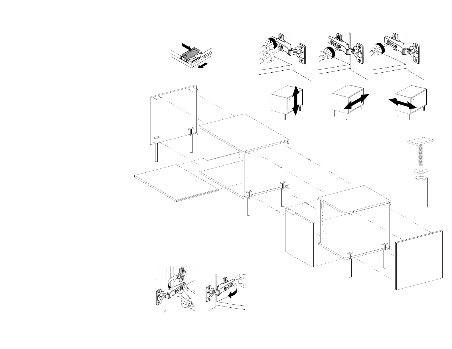
Remove drawers (extend to open position and release
catches monted on underside of drawer) or doors
(using quick release clips).
Theremoval of drawers/doors does notrequire tools.
Note location of drawers as they have been preadjusted
at factory and should be returned to original location.
Lay unit on back.
Remove side C from packagin and screw threaded
pins into sides
Put alignment dowels into outside holes (4 per side).
Assemble legs(see illustration 4).
Attach legs by positioning flatbar and threaded rods in
slots located on sides of box.
If two or more units areto be linked insert double ended
pins and press units together. Secure units tohether by
turning cam locks clockwise. Camlocks are located on
the underside of the top and bottom panels of each
unit.
Reattach sides to units securing side panels by turning
cam locks clockwise.
Tighten legs untilsthey rest firmly against underside
of unit.
Turns unit onto its legs. Lift and turn unit setting all legs
down simultaneously. Do not attempt to tip up unit
using the legsas leverage.
Attach drawer/doorspulls and replace drawer/doorsin
original locations. doors areinstalled with quick release
clip hinge and snap intoposition.
Drawers are attached as follows:
Push drawer slidesto closed position.
Placeback of drawer boxonslides and
pushdrawer to closed position until
drawer face is flush with front or unit.
To ensure drawer slideis fully inserted in
catch, fully opendrawer andpull slide
forward whilemaintaining pressure on
drawerface.
Ifnecessary, adjust verticallyby turning
plastic leveler located on catch.
1
2
3
4
5
6
7
8
9
10
1Drawer Removal 9Door Assembly
1Drawer Removal 9Door Adjustment
Press locking device
level on each side
Remove drawer
4Leg Assembly
Side C
Side C
Popular Indoor Furnishing manuals by other brands

Regency
Regency LWMS3015 Assembly instructions

Furniture of America
Furniture of America CM7751C Assembly instructions

Safavieh Furniture
Safavieh Furniture Estella CNS5731 manual

PLACES OF STYLE
PLACES OF STYLE Ovalfuss Assembly instruction

Trasman
Trasman 1138 Bo1 Assembly manual

Costway
Costway JV10856 manual


