Bentel Security BW-ODC User manual
D-305831 BW-ODC Installation Instructions 1
BW-ODC Bentel Security
English
PowerG, Outdoor Mirror PIR Motion Detector with Anti- masking and
Built-In Camera Installation Instructions
Italiano Rilevatore di movimento PIR a specchio, da esterno, con
antimascheramento, e telecamera incorporata, PowerG Istruzioni di installazione
Polski
Lustrzany czujnik ruchu PIR z funkcjąantymaskingu i wbudowaną
kamerą, do zastosowańzewnętrznych Instrukcja instalacji
ENGLISH
1. INTRODUCTION
Note: Operations described in these instructions applies to BW control panels. For further information related to operations with a different
control panel, refer to the control panel's instructions.
The BW-ODC is a 2-way, wireless outdoor digital mirror PIR detector with built-in camera. Activated upon PIR detection or upon demand, the
BW-ODC sends clear images to the Monitoring Station for alarm image verification.
The PIR motion detector’s features are as follows:
Operates with BW control panels (version 18 and higher)
Patented 8 independent quad PIR detectors (Octa-QUADTM) operating in true Quad configuration (patented) with true motion recognition
(TMR) processing for each of the 8 PIR detectors
Advanced Obsidian Black MirrorTM optics (patent pending)
Optimum performance even in poor weather conditions such as snow, rain, dust, wind, and direct sunlight
Tamper protection prevents opening and removal from wall
PowerG two-way Frequency Hopping Spread Spectrum FHSS-TDMA technology - provides robustness and reliability
Built-in link quality indicators enable installer to check signal quality without physically approaching the control panel
Robust housing with recessed window
Smart anti masking distinguishes between masking spray and rain
Alarm LED is visible in sunlight
Automatic termination of walk-test after 15 minutes
Microprocessor-controlled temperature compensation
Immunity to small pets
Built-in swivel bracket.
The camera’s features are as follows:
Up to 10 cameras can be enrolled
Images multiplexed from all enrolled cameras
Color and black & white images
Auto-setup
Camera tuning by simple walk-test
Day and night CMOS camera, with near IR illumination. This allows taking pictures in full darkness without letting the intruder know.
Instant capture: guarantees capture of fast moving intruder.
Optional AC power
An event records 2 images per second. 10-15 images total
2. INSTALLATION
2.1 Installation
A. Bracket installation (see Figure 2 on page 13). Fix the bracket firmly on a stable wall or pillar. The orientation of the fixed bracket must
provide for the orientation of the detector to be as parallel as possible to the surveyed ground surface.
B. Adjust the detector's horizontal and vertical angles (see Figure 3 on page 14), according to the surveyed ground surface. Set the vertical
angle position depending on the mounting height and coverage distance that you require. See Figure 3 and Table 1 for details. The
information refers to a relatively flat surveyed area. Verify the correct installation by using the walk test method.
C. Fasten the detector to the bracket (see Figure 2 on page 13, step 4).
D. To decrease false alarms, which can be triggered by pets, it is recommended to install the detector at a height of 2 to 2.5 meters from the
ground surface. In addition, vertical adjustment must be fixed on #4 or #5 position. It is recommended to direct the detector on a
background such as walls, houses, fences but not on open space.
Installation Notes:
The top cover should only be accessed by authorized service personnel or manufacturer. Do not obscure the detector field of view with large
objects. Install in position such that expected intruder motion is perpendicular to the zones of detection.
Alarms that could be triggered by conditions such as weather, blowing leaves and brush, or related environmental conditions, etc., need to be
considered when assessing the installation and application.
Table 1 – Vertical Adjustment Reference
Mounting Height Nominal Coverage Distance
2m / 6.7ft 4m / 13ft 6m / 20ft 8m / 26ft 10m / 33 ft 12m / 39 ft
3.0m / 10 ft - 1 2 2 3 3
2.5m / 8 ft 1 1 2 3 4 4
2.0m / 7 ft 1 2 3 4 5 5
1.5m
/
5 ft 2 3 4 5 5 -
D-305831 BW-ODC Installation Instructions 2
Notes:
1. For installation options to reduce the probability of false alarms from pets, see the grayed-in cells in Table 1.
2. For EN installations only and the distance ranges between 11 to 12 m (36 - 39ft), set the PIR sensitivity to "One region".
3. For situations where the beams are directed towards open space, the coverage distance specified in Table 1 - Vertical Adjustment
Reference may be exceeded.
2.2 Battery Insertion
It is recommended to perform the first batteries insertion on a flat surface (see Figure 4 on page 15). After battery insertion, the LED will flash for
60 seconds and then the detector will enter a 15 minutes' local diagnostic mode.
2.3. Enrollment
Refer to the BW control panel's Installer Guide and follow the procedure under the 02:ZONES/DEVICES option of the Installer Menu. A general
description of the procedure is provided in the following flow chart.
Step 1 Step 2 Step 3 Step 4
Enter the Installer menu and select
02:ZONES/DEVICES
Select ADD NEW DEVICE
See Note 1
Enroll the device (see Figure 5 on
page 16) or enter the device ID
Select a detector number for
the new detector
02:ZONES/DEVICES ADD NEW DEVICES
ENROLL NOW or
ENTR ID:XXX-XXXX
Z09:Motion Camera
ID No. 142-XXXX
MODIFY DEVICES
Step 5 Step 6 Step 7
Configure Location, Zone Type and
Chime parameters
Enter PARTITIONS.
See Note 2
Assign partitions to the detector by
pressing the ,
and/or buttons on the
panel
Z09.LOCATION
Z09.ZONE TYPE
Z09.SET CHIME
Z09/PARTITIONS Z09:P1P2 P3
means scroll and select
Notes:
[1] If the detector is already enrolled you can configure the detector parameters and assign partitions via the “Modify Devices” option – see Step
2.
[2] PARTITIONS will appear only if PARTITIONING was previously enabled in a panel that supports the Partitioning feature (for further details,
see "Partitioning" in the BW Installer Guide).
2.4. Configuring the Detector Parameters
Enter the DEVICE SETTINGS menu and follow the configuration instructions for the BW-ODC PIR detector as described below.
Option Configuration Instructions
ALARM LED Define whether or not to activate the alarm LED indication.
Optional settings: ON (default) and OFF.
PIR SENSITIVITY Define if the detector operates at regular or high PIR sensitivity, or that at least one detection zone must be crossed
before an alarm is triggered (One Region).
Optional settings: LOW (default), HIGH and One Region.
Note: For EN compliance, the detector should be set to "One Region".
DISARM ACTIVITY Define whether or not to set the activity time during Disarm mode.
Optional settings: NOT Active (default), YES – no delay, YES + 5s delay, YES + 15s delay, YES + 30s delay, YES + 1m
delay, YES + 2m delay, YES + 5m delay, YES + 10m delay, YES + 20m delay and YES + 60m delay.
OUTDOOR ANTI-M Enable or disable the outdoor anti-masking feature.
Optional settings: Disabled
(default)
and
Enabled.
ALARM Hours Define whether motion alarms are always enabled or only when dark (at night).
Optional settings: Day and Night (default) and Night only.
IMAGE COLOR Define whether the image will be in black & white or color.
Optional settings: Black & White (default) and Color.
IMAGE RESOLUTION Set the pixel quality of the image. Select 160 x 120 for lower quality or 320 x 240 for higher quality.
Optional settings: 320 x 240 (default) and 160 x 120.
IMAGE QUALITY Set the quality of the image.
Optional settings: High (default) and normal.
D-305831 BW-ODC Installation Instructions 3
Option Configuration Instructions
IMAGE BRIGHTNESS Set the brightness of the image.
Optional settings: Normal (default) -3, -2, -1, +1, +2 and +3.
IMAGE CONTRAST Set the contrast of the image.
Optional settings: Normal (default) -3, -2, -1, +1, +2 and +3.
2.5 Local Diagnostic Test
A. Set the detector in local diagnostic mode, as follows:
Open the detector’s bottom cover (see Figure 4, steps 1 - 3) and then press and release the tamper switch (see Figure 5). The LED will flash
for 60 seconds and then the detector will enter into 15 minutes' local diagnostic mode.
Note: The detector automatically enters into 15 minutes' local diagnostic mode after battery installation or Tamper switch recovery.
B. Adjust the detector in the horizontal plane to cover the required protected area.
C. Walk into the detectors field of view. Adjust the vertical plane to receive the maximum number of detections when crossing the entire 90°
pattern. Verify that the LED blinks each time your motion is detected, as you cross one Quad PIR. Then verify that the LED lights steadily
for 2 seconds as you cross the next adjacent Quad PIR. After alarm indication, the LED blinks three times and provides the received signal
strength indication (see Table 2).
Table 2 – Received Signal Strength Indication
LED response Reception
Green LED blinks Strong
Orange LED blinks Good
Red LED blinks Poo
r
No blinks No communication
Important! Reliable reception must be assured. Therefore, "poor" signal strength is not acceptable. If you receive a "poor" signal from the
detector, re-locate it and re-test until a "Good" or "Strong" signal strength is received.
Note: For detailed Diagnostics Test instructions refer to the control panel Installer's Guide.
The LED blinking, described above, is operative only in Local diagnostic mode. Upon each full detection (LED lights steadily for 2 seconds),
the control panel receives the alarm. If required, perform the detector's horizontal / vertical adjustments (see section 2.1 and Figure 3).
Important! Instruct the user to perform a walk test at least once a week, to verify proper operation of the detector.
D. Place a piece of cardboard on the detector’s front side to deliberately mask the optical window. Verify that after 2 minutes, the yellow LED
lights continuously (see Table 3 below) and the alarm control panel receives the masking alarm.
E. Remove the masking from the detector’s front side. Verify that the LED turns off after 30 seconds.
Table 3 – LED operation
LED Indications Event
Red Alarm LED blinks Stabilization (warm-up 60 sec)
Red Alarm LED ON 0.2 sec. Tamper open / close
Red Alarm LED blinks twice One quad PIR detection in diagnostic mode
Red Alarm LED on 2 sec. Intruder alarm
Yellow Indication LED ON AM detection
–
diagnostic mode
Yellow indication LED blinks slowly (0.2 sec. ON, 30 sec. OFF) AM detection
–
Normal mode
3. COMPLIANCE WITH STANDARDS
The BW-ODC complies with the following standards:
Europe: EN 300220, EN 301489, EN 62368-1, EN 60950-22, EN 50130-4, EN 50130-5, EN 50131-2-2, EN 50131-6, Type C, EN
50131-5-3, EN 50131-1 Grade 2 Class IV IP55
Hereby, Bentel Security S.r.l. declares that the radio equipment type BW-ODC is in compliance with Directive 2014/53/EU.
The full text of the EU declaration of conformity is available at the following internet address:
http://www.bentelsecurity.com/dc.
UK: This product is suitable for use in systems installed to conform to PD6662 at Grade 2 and environmental class 4. BS8243
W.E.E.E. Product Recycling Declaration
For information regarding the recycling of this product you must contact the company from which you originally purchased it. If you
are discarding this product and not returning it for repair then you must ensure that it is returned as identified by your supplier. This
product is not to be thrown away with everyday waste.
Directive 2012/19/EU Waste Electrical and Electronic Equipment.
APPENDIX: SPECIFICATIONS
OPTICAL
Black Mirror Max. Coverage Up to 12 m (40 ft) / 90°
Detector Technology 8 independent quad PIR detectors operating in true Quad configuration (See Figure 6 on page 16)
Pet Immunity Small pets
ELECTRICAL
Input Power Two 3V / 2400 mAh, CR17450 Lithium batteries manufactured by EVE/GP
Battery Life (for typical use) 3 years
Low Battery Threshold 4.0 V
Operation voltage 4 V to 6.5 V
Current consumption Min: 30 μA Max: 550 mA
Optional Mains Supply Additional to batteries, 7.5 V DC, 1.5 A

D-305831 BW-ODC Installation Instructions 4
FUNCTIONAL
IR Illumination 10 m (33 ft)
Picture Resolution 320x240 pixel QVGA o
r
160X120pixelQQVGA
Frame Rate 2 fps
WIRELESS
Frequency Band (MHz) 868-869
Maximum Tx Power 14 dBm @ 868 MHz
Communication Protocol PowerG
Tamper Alert Reported when a tamper event occurs and in any subsequent message, until the tamper switch is restored
MOUNTING
Mounting Type Wall mounting
Mounting Height 1.5 – 3.0 m (5 – 10 ft)
Horizontal Adjustment -45° to +45°, in 5° steps
V
ertical Adjustment 0° to -10°, in 2.5° steps
ENVIRONMENTAL
Operating Temperatures -35°C to 60°C (-31°F to 140°F)
Storage Temperatures -35°C to 60°C (-31°F to 140°F)
Humidity 95% max.
White Light Immunity Above 25000 lux
PHYSICAL
Size (H x L x W) 166 x 147 x 124 mm (6-9/16 x 5-13/16 x 4-7/8”)
Weight (with battery) 700 g (25 oz)
Color White
PATENTS U.S. Patents 7250605 l 6818881 l 5693943 (other patents pending)
WARRANTY
Visonic Limited (the “Manufacturer") warrants this product only (the "Product") to the original purchaser only (the “Purchaser”) against defective workmanship and materials under normal use of
the Product for a period of twelve (12) months from the date of shipment by the Manufacturer.
This Warranty is absolutely conditional upon the Product having been properly installed, maintained and operated under conditions of normal use in accordance with the Manufacturers
recommended installation and operation instructions. Products which have become defective for any other reason, according to the Manufacturers discretion, such as improper installation, failure
to follow recommended installation and operational instructions, neglect, willful damage, misuse or vandalism, accidental damage, alteration or tampering, or repair by anyone other than the
manufacturer, are not covered by this Warranty.
There is absolutely no warranty on software, and all software products are sold as a user license under the terms of the software license agreement included with such Product."
The Manufacturer does not represent that this Product may not be compromised and/or circumvented or that the Product will prevent any death and/or personal injury and/or damage to property
resulting from burglary, robbery, fire or otherwise, or that the Product will in all cases provide adequate warning or protection. The Product, properly installed and maintained, only reduces the risk
of such events without warning and it is not a guarantee or insurance that such events will not occur.
Conditions to Void Warranty: This warranty applies only to defects in parts and workmanship relating to normal use of the Products. It does not cover:
* damage incurred in shipping or handling;
* damage caused by disaster such as fire, flood, wind, earthquake or lightning;
* damage due to causes beyond the control of the Seller such as excessive voltage, mechanical shock or water damage;
* damage caused by unauthorized attachment, alterations, modifications or foreign objects being used with or in conjunction with the Products;
* damage caused by peripherals (unless such peripherals were supplied by the Seller;
* defects caused by failure to provide a suitable installation environment for the products;
* damage caused by use of the Products for purposes other than those for which they were designed;
* damage from improper maintenance;
* damage arising out of any other abuse, mishandling or improper application of the Products.
Items Not Covered by Warranty: In addition to the items which void the Warranty, the following items shall not be covered by Warranty: (i) freight cost to the repair centre; (ii) customs fees,
taxes, or VAT that may be due; (iii) Products which are not identified with the Seller's product label and lot number or serial number; (iv) Products disassembled or repaired in such a manner as to
adversely affect performance or prevent adequate inspection or testing to verify any warranty claim. Access cards or tags returned for replacement under warranty will be credited or replaced at
the Seller's option.
THIS WARRANTY IS EXCLUSIVE AND EXPRESSLY IN LIEU OF ALL OTHER WARRANTIES, OBLIGATIONS OR LIABILITIES, WHETHER WRITTEN, ORAL, EXPRESS OR IMPLIED,
INCLUDING ANY WARRANTY OF MERCHANTABILITY OR FITNESS FOR A PARTICULAR PURPOSE, OR OTHERWISE. IN NO CASE SHALL THE MANUFACTURER BE LIABLE TO
ANYONE FOR ANY CONSEQUENTIAL OR INCIDENTAL DAMAGES FOR BREACH OF THIS WARRANTY OR ANY OTHER WARRANTIES WHATSOEVER, AS AFORESAID.
THE MANUFACTURER SHALL IN NO EVENT BE LIABLE FOR ANY SPECIAL, INDIRECT, INCIDENTAL, CONSEQUENTIAL OR PUNITIVE DAMAGES OR FOR LOSS, DAMAGE, OR
EXPENSE, INCLUDING LOSS OF USE, PROFITS, REVENUE, OR GOODWILL, DIRECTLY OR INDIRECTLY ARISING FROM PURCHASER’S USE OR INABILITY TO USE THE PRODUCT,
OR FOR LOSS OR DESTRUCTION OF OTHER PROPERTY OR FROM ANY OTHER CAUSE, EVEN IF MANUFACTURER HAS BEEN ADVISED OF THE POSSIBILITY OF SUCH DAMAGE.
THE MANUFACTURER SHALL HAVE NO LIABILITY FOR ANY DEATH, PERSONAL AND/OR BODILY INJURY AND/OR DAMAGE TO
PROPERTY OR OTHER LOSS WHETHER DIRECT, INDIRECT, INCIDENTAL, CONSEQUENTIAL OR OTHERWISE, BASED ON A CLAIM THAT THE PRODUCT FAILED TO FUNCTION.
HOWEVER, IF THE MANUFACTURER IS HELD LIABLE, WHETHER DIRECTLY OR INDIRECTLY, FOR ANY LOSS OR DAMAGE ARISING UNDER THIS LIMITED WARRANTY, THE
MANUFACTURER'S MAXIMUM LIABILITY (IF ANY) SHALL NOT IN ANY CASE EXCEED THE PURCHASE PRICE OF THE PRODUCT INVOLVED, WHICH SHALL BE FIXED AS
LIQUIDATED DAMAGES AND NOT AS A PENALTY, AND SHALL BE THE COMPLETE AND EXCLUSIVE REMEDY AGAINST THE MANUFACTURER. SOME JURISDICTIONS DO NOT
ALLOW THE EXCLUSION OR LIMITATION OF INCIDENTAL OR CONSEQUENTIAL DAMAGES, SO THESE LIMITATIONS MAY NOT APPLY UNDER CERTAIN CIRCUMSTANCES.
When accepting the delivery of the Product, the Purchaser agrees to the said conditions of sale and warranty and he recognizes having been informed of.
The Manufacturer shall be under no liability whatsoever arising out of the corruption and/or malfunctioning of any telecommunication or electronic equipment or any programs.
The Manufacturers obligations under this Warranty are limited solely to repair and/or replace at the Manufacturer’s discretion any Product or part thereof that may prove defective. Any repair
and/or replacement shall not extend the original Warranty period. The Manufacturer shall not be responsible for dismantling and/or reinstallation costs. To exercise this Warranty the Product must
be returned to the Manufacturer freight pre-paid and insured. All freight and insurance costs are the responsibility of the Purchaser and are not included in this Warranty.
For sales in Israel only:
The Purchaser shall comply with the provisions of the Israeli Consumer Protection Law – 1981("Consumer Protection Law") related regulations, including the Israeli Consumer Protection
Regulations (Warranty Sticker), 5772-2012) ("Regulations"), including, without limitation (i) providing its customers with at least the minimum warranty required by the Consumer Protection Law,
and (ii) ensuring that a warranty certificate and a warranty sticker (as defined in the Regulations) ("Warranty Sticker") shall be attached to any sold Products and the date of the sale of the Product
to the consumer or the end-user shall be added in a readable manner on the Warranty Sticker.
In no event shall the Purchser’s compliance with the Consumer Protection Law and Regulations expand any of the Manufacturer's warranty obligations under this warranty, and the Purchaser
shall be responsible for any warranty that it provides with respect to the Products which exceeds or is different from this warranty.
This warranty shall not be modified, varied or extended, and the Manufacturer does not authorize any person to act on its behalf in the modification, variation or extension of this warranty. This
warranty shall apply to the Product only. All products, accessories or attachments of others used in conjunction with the Product, including batteries, shall be covered solely by their own warranty,
if any. The Manufacturer shall not be liable for any damage or loss whatsoever, whether directly, indirectly, incidentally, consequentially or otherwise, caused by the malfunction of the Product
due to products, accessories, or attachments of others, including batteries, used in conjunction with the Products. This Warranty is exclusive to the original Purchaser and is not assignable.
This Warranty is in addition to and does not affect your legal rights. Any provision in this warranty which is contrary to the Law in the state or country were the Product is supplied shall not apply.
Governing Law: This disclaimer of warranties and limited warranty are governed by the domestic laws of Israel.
Warning
The user must follow the Manufacturer’s installation and operational instructions including testing the Product and its whole system at least once a week and to take all necessary precautions for
his/her safety and the protection of his/her property.
* In case of a conflict, contradiction or interpretation between the English version of the warranty and other versions, the English version shall prevail.
© 2022 Johnson Controls. All rights reserved. JOHNSON CONTROLS and Bentel Security are trademarks and/or registered trademarks.
Unauthorized use is strictly prohibited.

D-305831 BW-ODC Istruzioni di Installazione 5
ITALIANO
2. INTRODUZIONE
Nota: Le informazioni presenti in queste istruzioni si applicano alle centrali BW. Per maggiori informazioni sul funzionamento con una centrale
diversa, fare riferimento alle istruzioni della centrale.
Il BW-ODC è un rilevatore PIR a specchio digitale per esterni, via radio, bidirezionale con telecamera incorporata. Attivato al momento del
rilevamento PIR o su richiesta, il BW-ODC invia immagini nitide alla centrale di vigilanza per la verifica visiva dell’allarme.
Le caratteristiche del rilevatore di movimento PIR sono le seguenti:
Funziona con le centrali BW (versione 18 e successive)
8 rilevatori PIR Quad indipendenti brevettati che funzionano in una vera configurazione Quad (brevettata) con reale riconoscimento del
movimento (TMR) elaborando dati per ciascuno degli 8 rilevatori PIR
Ottica avanzata Obsidian Black MirrorTM (brevetto in corso di registrazione)
Prestazioni ottimali anche in condizioni di brutto tempo, come neve, pioggia, polvere, vento e luce solare diretta
Protezione antisabotaggio contro l'apertura e la rimozione dalla parete
Tecnologia a spettro espanso a salto di frequenza bidirezionale BW FHSS-TDMA che assicura robustezza e affidabilità
Indicatori della qualità del collegamento incorporati che consentono all'installatore di controllare la qualità del segnale senza avvicinarsi
fisicamente alla centrale
Contenitore robusto con finestra incassata
Antimascheramento intelligente in grado di distingue tra schiuma spray e pioggia
LED di allarme visibile anche sotto la luce del sole
Interruzione automatica della prova di copertura dopo 15 minuti
Compensazione della temperatura controllata dal microprocessore
Immunità ai piccoli animali domestici
Staffa snodata incorporata
Le caratteristiche della telecamera sono le seguenti:
Fino a 10 telecamere per sistema BW
Immagini multiple da tutte le telecamere
Immagini a colori e in bianco e nero
Impostazione automatica
Regolazione della telecamera mediante una semplice prova di copertura
Telecamera CMOS diurna e notturna, con illuminazione a infrarossi, consente di scattare foto nella completa oscurità, senza che l'intruso
se ne accorga
Cattura istantanea: garantisce la cattura dell'intruso in rapido movimento
Alimentazione CA opzionale
Un evento registra 2 immagini al secondo, 10-15 immagini in totale
2. INSTALLAZIONE
2.1 Installazione
A. Installazione della staffa (vedere Figura 2 a pagina 13). Fissare saldamente la staffa a una parete o a una colonna stabile. L'orientamento
della staffa fissa deve essere il più possibile parallelo alla superficie sorvegliata.
B. Regolare gli angoli orizzontali e verticali del rilevatore (vedere Figura 3 a pagina 14), in base alla superficie sorvegliata. La posizione
dell'indicatore di angolo verticale per le varie combinazioni di altezza di installazione e distanza di copertura è indicata nella Tabella 1 (le
informazioni si riferiscono a un'area sorvegliata relativamente piatta. Verificare la regolazione verticale mediante una prova di copertura).
C. Fissare il rilevatore alla staffa (vedere Figura 2 a pagina 13, passaggio 4).
D. Per ridurre i falsi allarmi, che possono essere provocati dagli animali domestici, si consiglia di installare il rilevatore a un'altezza compresa
tra 2 e 2,5 metri dal terreno. Inoltre, la regolazione verticale deve essere fissata sulla posizione n. 4 o n. 5. Si consiglia di orientare il
rilevatore su uno sfondo come muri, case, recinzioni, ma non su uno spazio aperto.
Note di installazione:
Il coperchio superiore deve essere aperto solo dal personale di assistenza autorizzato o dal produttore. Non oscurare il campo visivo del
rivelatore con oggetti di grandi dimensioni. Installare in una posizione tale che il movimento previsto dell'intruso sia perpendicolare alle zone di
rilevamento.
Quando si valuta l'installazione e l'impiego, devono essere presi in considerazione gli allarmi che potrebbero essere attivati da condizioni quali,
condizioni meteorologiche, movimento di foglie e cespugli, o condizioni ambientali correlate, ecc.
Tabella 1 – Riferimenti per la regolazione verticale
Altezza di montaggio Distanza di copertura
2m 4 m 6 m 8 m 10 m 12 m
3,0 m - 1 2 2 3 3
2,5 m 1 1 2 3 4 4
2,0 m 1 2 3 4 5 5
1,5 m 2 3 4 5 5 -
Note:
1. Le celle in grigio nella Tabella 1 sono le opzioni di installazione consigliate per ridurre ulteriormente i falsi allarmi causati dagli animali
domestici.
2. Per installazioni conformi agli standard EN, e per distanze comprese tra 11 e 12 m, impostare la sensibilità PIR su Una regione.
3. Per le situazioni in cui il rilevatore è diretto verso uno spazio aperto, la distanza di copertura specificata nella Tabella 1 può essere superata.
2.2 Inserimento della batteria
Si consiglia di eseguire il primo inserimento della batterie su una superficie piana (vedere Figura 4 a pagina 15). Dopo l'inserimento della batteria,
il LED lampeggerà per 60 secondi e quindi il rilevatore entrerà in una modalità di diagnostica locale di 15 minuti.

D-305831 BW-ODC Istruzioni di Installazione 6
2.3. Registrazione
Consultare la Guida di installazione della centrale Serie BW e seguire la procedura indicata sotto l'opzione "02:ZONE/DISPOSIT" del menu di
installazione. Una descrizione generale della procedura è illustrata nel seguente diagramma di flusso.
Fase 1 Fase 2 Fase 3 Fase 4
Accedere al menu di installazione e
selezionare “02:ZONE/DISPOSITIVI”
Selezionare "AGG. NUOVO DISP."
Vedere Nota 1
Registrare il dispositivo (vedere
Figura 5 a pagina 16) o immettere
l'ID del dispositivo
Selezionare un numero di
zona per il nuovo rilevatore.
02:ZONE/DISPOSITIVI AGG. NUOVO DISP.
TRASMETTERE ORA o
INS. ID:XXX-XXXX
Z09:Sens Telecam
Nr. ID. 142-XXXX
MODIFICARE DISP.
Fase 5 Fase 6 Fase 7
Configurare i parametri posizione, tipo
di zona e campanello
Accedere a PARTIZIONI.
Vedere Nota 2
Assegnare le aree al rilevatore
premendo i pulsanti ,
e/o sulla
centrale
Z09.POSIZIONE
Z09.TIPO ZONA
Z09.CAMPANELLO
Z09/PARTIZIONI Z09:P1P2 P3
significa scorrere e selezionare
Note:
[1] Se il rilevatore è già registrato è possibile configurare i suoi parametri e assegnare le Aree tramite l'opzione “Modificare disp.” – vedere
Fase 2.
[2] PARTIZIONI apparirà solo se in precedenza è stata attivata l'opzione PARTIZIONI su una centrale che supporta la funzionalità Partizione
(per ulteriori dettagli, vedere "Aree" nella guida di installazione della centrale Serie BW).
2.4. Configurazione dei parametri del rilevatore
Accedere al menu OPZIONI DISP e seguire le istruzioni di configurazione relative al rilevatore BW-ODC, come descritto qui di seguito.
Opzione Istruzioni di configurazione
LED DI ALLARME Impostare se attivare o meno l'indicazione del LED di allarme.
Opzioni: ON (impostazione predefinita) e OFF.
PIR SENSIBILITA Impostare se il rilevatore funziona con una sensibilità PIR normale o alta, oppure che almeno una zona di rilevazione
deve essere attraversata prima che scatti un allarme (una regione).
Opzioni: BASSO (impostazione predefinita), ALTO e UNA REGIONE.
Nota: per la conformità EN, il rilevatore dovrebbe essere impostato su "UNA REGIONE".
Funzion. DISINS. Impostare se abilitare o meno il tempo di attività durante la modalità Disinserito.
Opzioni: NON Attivo (impostazione predefinita), Attivo-Sempre, Attivo-Pausa 5s, Attivo-Pausa 15s, Attivo-Pausa 30s,
Attivo-Pausa 1m, Attivo-Pausa 2m, Attivo-Pausa 5m, Attivo-Pausa 10m, Attivo-Pausa 20m e Attivo-Pausa 60m.
OUTDOOR ANTI-M Impostare se abilitare o disabilitare la funzionalità antimascheramento all'aperto.
Opzioni: Disabilitato (impostazione predefinita) e Abilitata.
ALLARME ora Impostare se gli allarmi di movimento sono attivati sempre oppure solo quando è buio (di notte).
Opzioni: Giorno e Notte (impostazione predefinita) e Solo Notte.
COLORE Immag. Impostare se l'immagine sarà in bianco e nero o a colori.
Opzioni: Bianco e Nero (impostazione predefinita) e Colori.
RISOLUZ. Immag. Impostare la risoluzione dell'immagine. Selezionare 160 x 120 per una qualità bassa o 320 x 240 per una qualità alta.
Opzioni: 320 x 240 (impostazione predefinita) e 160 x 120.
QUALIT. Immag. Impostare la qualità dell'immagine.
Opzioni: Alta (impostazione predefinita) e normale.
LUMINOS. Immag. Impostare la luminosità dell'immagine.
Opzioni: Normale (impostazione predefinita) -3, -2, -1, +1, +2 e +3.
CONTRASTO Immag Impostare il contrasto dell'immagine.
Opzioni: Normale (impostazione predefinita) -3, -2, -1, +1, +2 e +3.
2.5 Prova di posizionamento locale
A. Impostare il rilevatore in modalità prova di posizionamento locale, nel modo seguente:
Aprire il coperchio inferiore del rilevatore (vedere la Figura 4, fasi 1 – 3), quindi premere e rilasciare l'interruttore antisabotaggio (vedere Figura
5). Il LED lampeggerà per 60 secondi e quindi il rilevatore entrerà nella modalità di prova di posizionamento locale per 15 minuti.

D-305831 BW-ODC Istruzioni di Installazione 7
Nota: il rilevatore entra automaticamente nella modalità prova di posizionamento locale di 15 minuti, dopo l'installazione della batteria o il
ripristino dell'interruttore antisabotaggio.
B. Regolare il rilevatore sul piano orizzontale per coprire l'area necessaria.
C. Camminare nel campo visivo del rilevatore. Regolare il piano verticale per ricevere il numero massimo di rilevamenti quando si attraversa
l'intero campo di 90. Verificare che il LED lampeggi ogni volta che viene rilevato il movimento, mentre si attraversa un PIR Quad.
Dopodiché, verificare che il LED resti acceso per 2 secondi mentre si attraversa il PIR Quad adiacente. Dopo l'indicazione dell'allarme, il
LED lampeggia tre volte e fornisce l'indicazione dell’intensità del segnale ricevuto (vedere la Tabella 2).
Tabella 2 – Indicazione dell’intensità del segnale ricevuto
Risposta LED Ricezione
Il LED verde lampeggia Forte
Il LED arancione lampeggia Buona
Il LED rosso lampeggia Scarsa
Nessun lampeggiamento Comunicazione assente
IMPORTANTE! È necessario assicurare una ricezione affidabile. Pertanto, un’intensità di segnale "Scarsa" non è accettabile. Se si riceve un
segnale "scarso" dal rilevatore, riposizionare il dispositivo e rieseguire il test fino a ottenere un’intensità del segnale "buona" o "forte".
Nota: per istruzioni dettagliate sulla Prova di Posizionamento, fare riferimento alla Guida di installazione della centrale.
Il LED lampeggiante, descritto qui sopra, è operativo solo in modalità Prova di Posizionamento Locale. Dopo ciascun rilevamento completo (il
LED resta acceso per 2 secondi), la centrale riceve l'allarme. Se necessario, eseguire regolazioni orizzontali/verticali del rilevatore (vedere la
sezione 2.1 e la Figura 3 a pagina 14).
Importante! Invitare l'utente ad eseguire una prova di copertura almeno una volta alla settimana, per verificare il corretto funzionamento del
rilevatore.
D. Posizionare un pezzo di cartone sul lato anteriore del rilevatore per mascherare intenzionalmente la finestra ottica. Verificare che, dopo 2
minuti, il LED giallo si accenda e resti acceso (vedere la Tabella 3 seguente) e la centrale riceva l'allarme di mascheramento.
E. Rimuovere il pezzo di cartone dal lato anteriore del rilevatore. Verificare che il LED si spenga dopo 30 secondi.
Tabella 3 – Funzionamento dei LED
Indicazioni dei LED Evento
Il LED di allarme rosso lampeggia Stabilizzazione (60 sec. di riscaldamento)
LED di allarme rosso acceso pe
r
0,2 sec. Antisabotaggio aperto/chiuso
Il LED di allarme rosso lampeggia due volte Un rilevamento PIR Quad nella modalità prova di posizionamento
LED di allarme rosso acceso pe
r
2 sec. Allarme intruso
LED di segnalazione giallo acceso Rilevazione Antimascheramento
–
Modalità prova di posizionamento
Il LED di segnalazione giallo lampeggia lentamente (0,2 sec. acceso,
30 sec. spento)
Rilevazione Antimascheramento – Modalità normale
3. CONFORMITÀ CON GLI STANDARD
Il BW-ODC è progettato per essere conforme alle seguenti norme:
Europa (UE): EN 300220, EN 301489, EN 62368-1, EN 60950-22, EN 50130-4, EN 50130-5, EN 50131-2-2, EN 50131-6, Tipo C,
EN 50131-5-3, EN 50131-1 Grado 2 Classe IV IP55
Con la presente, Bentel Security S.r.l. dichiara che il tipo di apparecchiatura radio BW-ODC è conforme alla Direttiva 2014/53/UE.
Il testo completo della dichiarazione di conformità UE è disponibile al seguente indirizzo Internet: http://www.bentelsecurity.com/dc.
R.A.E.E. Dichiarazione sul riciclaggio del prodotto
Per informazioni sul riciclaggio di questo prodotto è necessario contattare l’azienda presso la quale esso era stato acquistato. Se
questo prodotto viene gettato via e non viene restituito per la riparazione, è necessario assicurarsi che esso venga restituito,
attenendosi alle informazioni del fornitore. Questo prodotto non può essere smaltito nei rifiuti domestici.
Direttiva 2012/19/UE sui rifiuti di apparecchiature elettriche ed elettroniche.

D-305831 BW-ODC Istruzioni di Installazione 8
APPENDICE: SPECIFICHE
OTTICHE
Copertura massima specchio
nero Fino a 12 m / 90°
Tecnologia del rilevatore 8 rilevatori PIR Quad indipendenti che operano in configurazione Quad reale (vedere Figura 6 a pagina 16)
Immunità agli animali domestici Piccoli animali domestici
ELETTRICHE
Alimentazione Due batterie al litio da 3 V / 2400 mAh, CR17450, prodotte da EVE o GP
Durata batteria (per uso normale) 3 anni
Soglia batteria bassa 4,0 V
Tensione di funzionamento Da 4 V a 6,5 V
Consumo di corrente Min: 30 uA, Max: 550 mA
Alimentazione di rete opzionale In aggiunta alle batterie, 7,5 Vcc, 1,5 A
FUNZIONALI
Illuminazione a infrarossi 10 m
Risoluzione delle immagini 320x240 pixel QVGA o 160X120pixelQQVGA
Frequenza frame 2 fps
RADIO
Banda di frequenza (MHz) 868-869
Potenza di trasmissione
massima 14 dBm @ 868 MHz
Protocollo di comunicazione PowerG
Avviso sabotaggio Segnalato quando si verifica un evento di sabotaggio e in ogni trasmissione successiva, fino a quando non
viene ripristinato l'interruttore antisabotaggio
MONTAGGIO
Tipo di montaggio Montaggio a parete
Altezza di montaggio 1,5 – 3,0 m
Regolazione orizzontale Da -45° a +45°, con passi di 5°
Regolazione verticale Da 0° a -10°, con passi di 2,5°
AMBIENTALI
Temperatura di funzionamento Da -35°C a 60°C
Temperatura di stoccaggio Da -35°C a 60°C
Umidità 95% max.
Immunità alla luce bianca Superiore a 25000 lux
FISICHE
Dimensioni (A x L x P) 166 x 147 x 124 mm
Peso (con batteria) 700 g
Colore Bianco
BREVETTI Brevetti U.S.A 7250605 6818881 5693943 (altri brevetti in corso di registrazione)
© 2022 Johnson Controls. Tutti i diritti riservati. JOHNSON CONTROLS e Bentel Security sono marchi e/o marchi registrati. L'uso non autorizzato
è severamente proibito.

D-305831 BW-ODC Instrukcja obsługi 9
POLSKI
1. WSTĘP
BW-ODC to 2-kierunkowy, bezprzewodowy, lustrzany, cyfrowy czujnik ruchu PIR z wbudowanąkamerą. Czujnik BW-ODC wysyła wyraźne
obrazy do stacji monitorowania w celu ich zweryfikowania po wystąpieniu alarmu w wyniku uaktywnieniu czujnika PIR lub po aktywacji ręcznej.
Funkcje czujnika ruchu PIR:
8 niezależnych, opatentowanych, poczwórnych detektorów PIR (Octa-QUADTM) pracujących w konfiguracji Quad (opatentowanej) z obróbką
rzeczywistego wykrywania ruchu (TMR) dla każdego z 8 czujników PIR
Układ optyczny Advanced Obsidian Black MirrorTM (zgłoszony do opatentowania)
Optymalne działanie nawet w niekorzystnych warunkach pogodowych, jak np. śnieg, deszcz, zapylanie, wiatr i bezpośrednie
nasłonecznienie
Zabezpieczenie antysabotażowe uniemożliwia otwarcie urządzenia i demontażze ściany
Dwukierunkowa technologia PowerG Frequency Hopping Spread Spectrum FHSS-TDMA — odporność i niezawodność
Wbudowane wskaźniki jakości połączenia umożliwiająinstalatorowi sprawdzenie jakości sygnału bez podchodzenia do centrali
Wytrzymała obudowa z wpuszczonym okienkiem
Funkcja inteligentnego antymaskowania rozróżnia zamalowanie urządzenia farbąw aerozolu i deszcz
Dioda LED alarmu jest widoczna w pełnym słońcu
Funkcja automatycznego zakończenia testu z obchodem po 15 minutach
Funkcja kompensacji temperatury sterowana mikroprocesorem
Odporna na małe zwierzęta
Wbudowany uchwyt obrotowy
Funkcje kamery:
Do 10 kamer w systemie
Możliwość multipleksowania obrazów z wielu kamer
Obrazy czarno-białe i kolorowe
Automatyczna konfiguracja
Dostrojenie kamery podczas testu przejścia
Kamera CMOS z funkcjądzień/noc i podświetleniem w podczerwieni. Umożliwia to dyskretne robienie zdjęć przy pełnym zaciemnieniu, bez
niepokojenia intruza.
Natychmiastowe przechwytywanie: gwarancja sfotografowania szybkiego intruza.
Opcjonalne zasilanie prądem przemiennym
W zdarzeniu można zarejestrować2 obrazy na sekundę. Łącznie 10–15 obrazów.
2. INSTALACJA
2.1 Instalacja
A. Instalacja wspornika (patrz Rysunek 2 na stronie 13). Przymocuj wspornik do mocnej ściany lub słupka. Należy zachowaćrównoległość
wspornika względem powierzchni, która będzie monitorowana.
B. Ustaw kąt czujnika względem poziomu i pionu (patrz Rysunek 3 na stronie 14) zależnie od powierzchni, która będzie monitorowana. W
Tabeli 1 przedstawiono kombinacje wysokości montażu w pionie oraz zasięg czujnika. Podane dane dotycząwzględnie płaskiej
powierzchni. Ustawienie w pionie można sprawdzić, przeprowadzając test przejścia.
C. Przymocuj czujnik do wspornika (patrz Rysunek 2 na stronie 13, krok 4).
D. W celu zredukowania ilości fałszywych alarmów, które mogąbyćwywołane przez zwierzęta, zaleca sięmontażczujnika na wysokości 2 –
2,5 metra od podłoża. Dodatkowo, regulator wysokości powinien byćustawiony w pozycji #4 lub #5. Zaleca sięrównieżskierowanie
czujnika na stały obiekt jak ściana lub ogrodzenie, nie zaśna otwartąprzestrzeń.
Uwagi do instalacji:
Górna pokrywa powinna byćotwierana jedynie przez autoryzowanego instalatora bądźproducenta. Nie należy blokowaćpola widzenia czujnika
dużymi obiektami. Należy instalowaćw miejscu gdzie oczekiwany ruch intruza jest prostopadły do stref pola widzenia czujnika.
Przed instalacjąnależy wziąć pod uwagęwpływ czynników środowiskowych takich jak pogoda, ruch liści, pyłu, piasku, innych oraz dopasować
miejsce instalacji do tych czynników.
Tabela 1. Wysokość montażu i zasięg czujnika
Wysokość mocowania Zasięg
2m 4m 6m 8m 10m 12m
3,0 m - 1 2 2 3 3
2,5 m 1 1 2 3 4 4
2,0 m 1 2 3 4 5 5
1,5 m 23455-
Uwagi:
1. Szare elementy w Tabeli 1 sąalternatywnymi metodami instalacji rekomendowanymi w celu zmniejszenia ilości fałszywych alarmów
spowodowanych przez zwierzęta.
2. Dla instalacji zgodnych z normami EN oraz dla instalacji z zasięgiem pomiędzy 11 a 12 m, ustaw czułość czujnika na poziomie JEDNA
STREFA.
3. W sytuacji kiedy wiązki czujnika sąskierowane na otwartąprzestrzeń, pokrycie wskazane w Tabeli 1 może zostaćprzekroczone.
2.2 Zakładanie baterii
Zaleca sięwykonanie pierwszego włożenia baterii na płaskiej powierzchni (patrz Rysunek 4 na stronie 15). Po włożeniu baterii dioda LED
będzie migaćprzez 60 sekund, a następnie czujnik przełączy sięw trwający 15 minut lokalny tryb diagnostyczny.

D-305831 BW-ODC Instrukcja obsługi 10
2.3. Zapis
Należy zapoznaćsięz podręcznikiem instalacji centrali GTI ONE i wykonaćczynności opisane w opcji „02:URZADZ./LINIE” menu instalatora.
Poniżej na diagramie zamieszczono ogólny opis tej procedury.
Krok 1 Krok 2 Krok 3 Krok 4
Otwórz menu instalatora i wybierz
opcję02:URZADZ./LINIE
Wybierz opcjęDODAJ URZADZ.
Patrz Uwaga 1
Zarejestruj urządzenie (patrz
Rysunek 5 na stronie 16) lub
podaj jego identyfikato
r
Wybierz numer nowego
czujnika
02:URZADZ./LINIE DODAJ URZADZ.
WYSLIJ SYGNAL INTR lub
WPROW. ID:xxx-xxxx
L09:CZ.RUCHU+KAMID
ID No. 142-XXXX
ZMIEN PARAM.URZ.
Krok 5 Krok 6 Krok 7
Skonfiguruj parametry położenia, typu
linii i sygnału dźwiękowego
Otwórz menu PARTYCJE
Patrz Uwaga 2
Przydziel partycje do czujnika,
naciskając przyciski ,
i/lub na centrali
L09:LOKALIZACJA
L09:TYP LINII
L09:DZWIEK
L09:PARTYCJA L09:P1P2 P3
oznacza przewijanie i wybierz
Uwaga:
[1] Jeśli czujnik jest jużzapisany, można skonfigurowaćjego parametry i przydzielićpartycje przy użyciu opcji ZMIEN PARAM.URZ. — patrz
krok 2.
[2] Opcja PARTYCJA pojawi siętylko wtedy, gdy wcześniej włączono funkcjęPARTYCJONOWANIA w centrali, która jąobsługuje (więcej
informacji na ten temat można znaleźć w rozdziale „Partycjonowanie” w podręczniku instalacji centrali GTI ONE).
2.4. Konfigurowanie parametrów czujnika
Otwórz menu xxx:USTAWIENIA i postępuj zgodnie z przedstawionymi poniżej instrukcjami dotyczącymi czujnika PIR BW-ODC.
Opcja Instrukcje dotyczące konfiguracji
DIODA LED Umożliwia włączenie lub wyłączenie wskazania diody LED alarmu.
Ustawienia opcjonalne: WŁ. (domyślnie) i WYŁ.
CZULOSC PIR Umożliwia wybór czułości PIR — standardowej lub wysokiej, a także konieczności przekroczenia co najmniej jednej
strefy wykrywania przed wyzwoleniem alarmu (funkcja JEDNA STREFA).
Ustawienia opcjonalne: CZULOSC NISKA (domyślnie), CZULOSC WYSOKA i JEDNA STREFA.
Uwaga: W celu zapewnienia zgodności z normami EN należy ustawićopcję„JEDNA STREFA”.
REAKCJA ROZBR. Umożliwia włączenie lub wyłączenie czasu aktywności w trybie rozbrojenia.
Ustawienia opcjonalne: NIE AKTYWNY (domyślnie), TAK – brak opóźnienia, TAK + 5 s opóźnienia, TAK + 15 s
opóźnienia, TAK + 30 s opóźnienia, TAK + 1 m opóźnienia, TAK + 2 m opóźnienia, TAK + 5 m opóźnienia, TAK + 10
m opóźnienia, TAK + 20 m opóźnienia i TAK + 60 m opóźnienia.
CZ. ZEWN. AM Umożliwia włączenie lub wyłączenie funkcji antymaskingu.
Ustawienia opcjonalne: Wyłączona (domyślnie) i Włączona.
GODZINY ALARM. Umożliwia określenie, czy alarmy ruchu sązawsze włączone, czy tylko w ciemności (w nocy).
Ustawienia opcjonalne: DZIEN I NOC (domyślnie) i TYLKO NOC.
KOLOR CZY CZ/B Umożliwia określenie, czy obraz ma byćczarno-biały czy kolorowy.
Ustawienia opcjonalne: CZARNO-BIALE (domyślnie) i KOLOROWE.
ROZDZ. ZDJECIA Umożliwia określenie rozdzielczości zdjęcia w pikselach. Można wybraćrozdzielczość 160 x 120 pikseli (niższa
j
akość) lub 320 x 240 pikseli (Wyższa jakość).
Ustawienia opcjonalne: 320 x 240 (domyślnie) i 160 x 120.
JAKOSC ZDJEC Umożliwia określenie jakości zdjęcia.
Ustawienia opcjonalne: WYSOKA (domyślnie) i NORMALNY.
JASNOSC ZDJECIA Umożliwia określenie jasności zdjęcia.
Ustawienia opcjonalne: NORMALNY (domyślnie) -3, -2, -1, +1, +2 i +3.
KONTRAST ZDJECIA Umożliwia określenie kontrastu zdjęcia.
Ustawienia opcjonalne: NORMALNY (domyślnie) -3, -2, -1, +1, +2 i +3.

D-305831 BW-ODC Instrukcja obsługi 11
2.5 Lokalny test diagnostyczny
A. Przełącz czujnik w tryb lokalnego testu diagnostycznego. Wykonaj następujące czynności:
Otwórz dolnąpokrywęczujnika (patrz Rysunek 4 na stronie 15, kroki 1–3), a następnie naciśnij i zwolnij wyłącznik sabotażowy (patrz Rysunek
5 na stronie 16). Dioda LED będzie migaćprzez 60 sekund, a następnie czujnik przełączy sięw trwający 15 minut lokalny tryb diagnostyczny.
Uwaga: czujnik automatycznie przełączy sięw trwający 15 minut lokalny tryb diagnostyczny po założeniu baterii lub ponownym załączeniu
wyłącznika sabotażowego.
B. Ustaw czujnik w płaszczyźnie poziomej w taki sposób, aby objąć zasięgiem wymagany obszar wykrywania.
C. Wejdźw pole widzenia czujnika. Ustaw czujnik w płaszczyźnie pionowej w taki sposób, aby uzyskaćmaksymalnąliczbęaktywacji przy
naruszaniu całego obszaru 90. Sprawdź, czy dioda LED miga po każdym wykryciu ruchu przy naruszaniu jednego czujnika Quad PIR.
Następnie sprawdź, czy dioda LED jest stale włączona przez 2 sekundy przy naruszaniu sąsiadującego czujnika Quad PIR. Po wskazaniu
alarmu dioda LED mignie trzy razy i wskaże moc odbieranego sygnału (patrz Tabela 2).
Tabela 2. Wskazanie mocy odbieranego sygnału
Odpowiedźdiody LED Odbiór
Zielona dioda LED miga Silny
Pomarańczowa dioda LED miga Dobry
Czerwona dioda LED miga Słaby
Brak migania Brak komunikacji
WAŻNE! Należy zapewnićstabilny odbiór. Należy unikaćustawienia, w którym występuje „słaby” odbiór. Jeśli odbierany poziom sygnału z
czujnika to „słaby”, należy zmienićjego położenie i wykonywaćtest ażdo uzyskania poziomu „dobry”.
Uwaga: szczegółowe instrukcje dotyczące testu diagnostycznego można znaleźć w podręczniku instalacji centrali.
Opisana powyżej funkcja migania diody LED jest dostępna tylko w trybie lokalnego testu diagnostycznego. Po każdym pełnym wykryciu (dioda
LED jest stale włączona przez 2 sekundy) do centrali jest wysyłany alarm. W razie potrzeby wyreguluj ustawienie czujnika w poziomie i pionie
(patrz punkt 2.1 i Rysunek 3 na stronie 14).
Ważne! Należy poinstruowaćużytkownika o konieczności wykonania testu z obchodem przynajmniej raz na tydzieńw celu potwierdzenia
poprawności działania czujnika.
D. Umieść kawałek kartonu z przodu czujnika, aby zasłonićokienko optyczne. Sprawdź, czy po 2 minutach żółta dioda LED jest stale włączona
(patrz Tabela 3 poniżej), a do centrali jest wysyłany alarm zamaskowania.
E. Zdejmij maskowanie z czujnika. Sprawdź, czy dioda LED wyłączy siępo 30 sekundach.
Tabela 3. Działanie diody LED
Wskazania diod LED Zdarzenie
Czerwona dioda LED alarmu miga Stabilizacja (rozgrzewanie 60 s)
Czerwona dioda LED alarmu włączona przez 0,2 s Otwarcie/zamknięcie wyłącznika sabotażowego
Czerwona dioda LED alarmu miga dwukrotnie Jedno wykrycie przez czujnik Quad PIR w trybie diagnostycznym
Czerwona dioda LED alarmu włączona przez 2 s Alarm włamaniowy
Żółta dioda LED wskaźnika włączona Wykrycie AM — tryb diagnostyczny
Żółta dioda LED wskaźnika miga powoli (włączona 0,2 s,
wyłączona 30 s)
Wykrycie AM — tryb normalny
3. ZGODNOŚĆ Z NORMAMI
Czujnik BW-ODC zostałzaprojektowany zgodnie z następującymi normami:
Europa (CE): EN 300220, EN 301489, EN 62368-1, EN 60950-22, EN 50130-4, EN 50130-5, EN 50131-2-2, EN 50131-6, Typ C,
EN 50131-5-3, EN 50131-1 Stopień2 Klasa IV IP55
Bentel Security S.r.l. niniejszym oświadcza, że typ urządzenia radiowego BW-ODC jest zgodny z dyrektywą2014/53/UE.
Pełny tekst deklaracji zgodności UE jest dostępny pod następującym adresem internetowym: http://www.bentelsecurity.com/dc.
Deklaracja W.E.E.E. dotycząca recyklingu produktu
W celu uzyskania informacji dotyczących recyklingu tego produktu należy skontaktowaćsięze sprzedawcą. Jeśli produkt podlega
utylizacji i nie jest zwracany celem naprawy, wówczas należy zapewnićzwrot w sposób ustalony z dostawcą. Tego produktu nie wolno
wyrzucaćwraz z codziennymi odpadkami.
Dyrektywa 2012/19/UE dotycząca zużytego sprzętu elektrycznego i elektronicznego.

D-305831 BW-ODC Instrukcja obsługi 12
DODATEK: DANE TECHNICZNE
DANE UKŁADU OPTYCZNEGO
Maks. zasięg czarnego lustra Maks. 12 m / 90°
Sposób wykrywania 8 niezależnych detektorów Quad PIR pracujących w prawdziwej konfiguracji Quad (Patrz Rysunek 6 na
stronie 16)
Odporność na zwierzęta Małe zwierzęta
DANE ELEKTRYCZNE
Zasilanie wejściowe Dwie baterie 3V. 2400 mAh, litowe, CR17450, wyprodukowane przez EVE bądźGP
Ż
ywotność baterii (standardowe
użycie) 3 lata
Wartość progowa
rozładowanych baterii 4,0 V
Napięcie pracy od 4 V do 6,5 V
Obecne zużycie Min: 30 μA Max: 550 mA
Opcjonalne zasilanie z sieci
elektrycznej Dodatkowo oprócz baterii, 7,5 V, 1,5 A (p
r
ąd stały)
DANE FUNKCJONALNE
Podświetlenie w podczerwieni 10 m
Rozdzielczość obrazu 320x240 pikseli QVGA lub 160x120 pikseli QQVGA
Szybkość zapisu 2 kl./s
DANE TRANSMISJI
BEZPRZEWODOWEJ
Pasmo częstotliwości (MHz) 868-869
Maks. moc nadawania 14 dBm przy 868 MHz
Protokółkomunikacji PowerG
Ostrzeżenie o sabotażuZgłaszane po wystąpieniu nowe zdarzenia sabotażu i potem w każdym, kolejno wysyłanym komunikacie
ażdo ponownego załączenia wyłącznika sabotażowego.
MOCOWANIE
Typ mocowania Montażna ścianie
Wysokość mocowania 1,5 – 3,0 m
Regulacja pozioma od -45° do +45°, w krokach co 5°
Regulacja pionowa od 0° do -10°, w krokach co 2,5°
DANE
Ś
RODOWISKOWE
Temperatura działania od -35°C do 60°C
Temperatura przechowywania od -35°C do 60°C
Wilgotność Maks. 95%
Odporność na światło białePowyżej 25000 luksów
DANE FIZYCZNE
Wymiary (wys. x dł. x szer.) 166 x 147 x 124 mm
Waga (z baterią)700 g
Kolor Biały
PATENTY Patenty USA 7250605 6818881 5693943 (inne patenty w trakcie rejestracji)
© 2022 Johnson Controls. Wszystkie prawa zastrzeżone. JOHNSON CONTROLS i Bentel Security stanowiąznaki towarowe lub zarejestrowane
znaki towarowe. Ich nieautoryzowane wykorzystywanie jest surowo wzbronione.

D-305831 Installation Instructions / Istruzioni di Installazione / Instrukcja obsługi 13
PICTURES / ILLUSTRAZIONI / RYSUNKI
A. IR LEDs
B. Indication LED
C. Camera
D. External power LED
E. Alarm LED
A. LED infrarossi
B. LED di segnalazione
C. Telecamera
D. LED alimentazione esterna
E. LED allarme
A. Diody LED podczerwieni
B. Wskaźnik LED
C. Kamera
D. Dioda LED zasilania zewn
E. Dioda LED alarmu
Figure 1. External View / Figura 1. Vista esterna / Rysunek 1. Widok zewnętrzny
Correct Installation
Installazione giusta
Właściwa instalacja
Incorrect Installation
Installazione sbagliata
Niewłaściwa instalacja
A. Mark drilling point
B. Screw hole for wall tamper
C. Drill
D. Fasten
E. Three long screws
F. Two short screws
Note: The 2 screw holes enable adjustment
of the bracket on the wall, if needed,
following the walk test.
A. Segnare i punti di foratura
B. Foro per la vite dell’antistrappo
C. Forare
D. Serrare
E. Tre viti lunghe
F. Due viti corte
Nota: i fori delle 2 viti consentono di regolare
la staffa a parete, se necessario, in base alla
prova di copertura.
A. Zaznaczyćmiejsce wiercenia
B. Otwór wkrętu do zab. antysabot. na
ścianie
C. Wywiercić
D. Przymocować
E. Trzy długie wkręty
F. Dwa krótkie wkręty
Uwaga: 2 otwory na wkręty umożliwiająw
razie potrzeby ustawienie wspornika na
ścianie po przeprowadzeniu testu z
obchodem.
Figure 2 – Installation / Figura 2 – Installazione / Rysunek 2. Instalacja

D-305831 Installation Instructions / Istruzioni di Installazione / Instrukcja obsługi 14
HORIZONTAL ADJUSTMENT (-45° to +45°) | REGOLAZIONE ORIZZONTALE (da -45a +45) | REGULACJA W POZIOMIE (od -45° do +45°)
1. Release locking
2. Adjust
3. Lock
1. Svitare le viti
2. Regolare
3. Bloccare
1. Zwolnićblokadę
2. Ustawić
3. Zablokować
VERTICAL ADJUSTMENT (0° to -10° in 2.5° clicks / steps) | REGOLAZIONE VERTICALE (da 0a -10con scatti/incrementi di 2,5) |
REGULACJA W PIONIE (od 0° do -10° z przeskokiem co 2,5°)
4. Release locking
5. Adjust
6. Lock
A. Vertical angle steps
4. Svitare la vite
5. Regolare
6. Bloccare
A. Passi dell’angolo verticale
4. Zwolnićblokadę
5. Ustawić
6. Zablokować
A. Stopniowa regulacja kąta względem pionu
COVER CLOSURE | CHIUSURA DEL COPERCHIO | ZAMKNIĘCIE POKRYWY
7. Turn cover and push slider
8and 9. Put back cover
10. Secure with screw
7. Inclinare il coperchio e inserirlo nella
scanalatura
8e 9. Rimontare il coperchio
10. Fissare con la vite
7. Obrócićobudowęi nacisnąć suwak
8i 9. Założyćz powrotem pokrywę
10. Zamocowaćwkrętami
Figure 3 – Adjustment and Cover Closure / Figura 3 – Regolazione e chiusura del coperchio / Rysunek 3. Ustawienie i zamknięcie obudowy
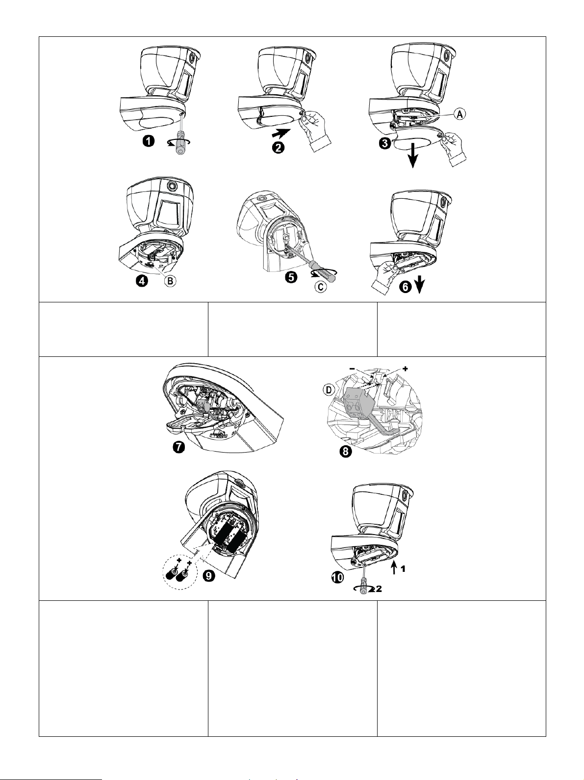
D-305831 Installation Instructions / Istruzioni di Installazione / Instrukcja obsługi 15
A. Tamper switch
B. Press firmly to release the bracket
C. 1 screw
Note: Steps 7 and 8 are optional for external
7.5 VDC power connection.
A. Deviatore antisabotaggio
B. Premere con forza per sganciare la staffa
C. 1 vite
Nota: I passaggi 7 e 8 sono opzionali per il
collegamento dell'alimentazione esterna da
7,5 Vcc.
A. Wyłącznik sabotażowy
B. Nacisnąć mocno, aby zwolnićwspornik
C. 1 wkręt
Uwaga: Wykonanie punktów 7 i 8 jest
opcjonalne w przypadku podłączenia
zewnętrznego zasilania 7,5 V (prąd stały).
D. Snap the terminal block into place.
Caution! Risk of explosion if battery is
replaced by an incorrect type. Dispose of
used battery according to the manufacturer's
instructions.
Caution! The battery used in this device may
present a risk of fire or chemical burn if
mistreated. Do not disassemble, heat above
66°C, or incinerate. Replace battery with
CR17450 Lithium batteries manufactured by
EVE/GP only. Dispose of used battery
promptly. Keep away from children. Do not
disassemble and do not dispose of in fire.
D. Agganciare in posizione la morsettiera.
Attenzione! Rischio di esplosione qualora la
batteria venisse sostituita con una batteria di
tipo errato. Smaltire la batteria usata in
conformità con le istruzioni del produttore.
Attenzione! La batteria utilizzata in questo
dispositivo può provocare ustioni da fiamma
o chimiche, se maltrattata. Non smontare,
riscaldare oltre i 66°C, o bruciare. Sostituire
la batteria solo con batterie al litio CR17450
prodotte da EVE o GP. Smaltire
immediatamente la batteria usata. Tenere
lontano dai bambini. Non smontare e non
gettare nel fuoco.
D. Zatrzasnąć listwęzaciskowąna miejscu
Przestroga! Wymiana baterii na baterie
niewłaściwego typu grozi eksplozją. Zużyte
baterie należy utylizowaćzgodnie z
instrukcjami producenta.
Przestroga! Baterie użyte w tym urządzeniu
mogąwywołaćryzyko pożaru lub wycieku
chemicznego jeśli sąnieprawidłowo traktowane.
Nie należy ich rozmontowywać, podgrzewać
powyżej 66°C oraz dopuszczaćo kontaktu z
ogniem. Wymieńbaterie jedynie na litowe
baterie CR17450 wyprodukowane przez EVE
bądźGP. Pozbądźsięzużytych baterii
natychmiast po wymianie. Chrońprzez dziećmi.
Nie rozmontowuj. Nie wrzucaj do ognia.
Figure 4 – Battery Insertion / Figura 4 – Inserimento della batteria / Rysunek 4. Zakładanie baterii

D-305831 Installation Instructions / Istruzioni di Installazione / Instrukcja obsługi 16
A. Alarm LED
B. Indication LED
C. Enroll button
D. Tamper switch
A. LED di allarme
B. LED di segnalazione
C. Pulsante di registrazione
D. Interruttore antisabotaggio
A. Dioda LED alarmu
B. Dioda LED wskaźnika
C. Przycisk rejestracji
D. Wyłącznik sabotażowy
Figure 5. BW-ODC / Figura 5. BW-ODC / Rysunek 5. BW-ODC
A. Top view
B. Side view of each detector
C. Image coverage range
A. Vista in pianta
B. Vista laterale di ciascun sensore
C. Copertura della telecamera
A. Widok z góry
B. Widok każdego detektora z boku
C. Zasięg przetwornika obrazu
Figure 6. Coverage Pattern / Figura 6. Diagramma di copertura / Rysunek 6. Charakterystyka zasięgu czujnika
e-mail: info@bentelsecurity.com
http: www.bentelsecurity.com
D-305831, BW-ODC Installation Instructions, English, Italian, Polish, Rev. 1, 05/22
Table of contents
Languages:
Popular Indoor Furnishing manuals by other brands

Regency
Regency LWMS3015 Assembly instructions

Furniture of America
Furniture of America CM7751C Assembly instructions

Safavieh Furniture
Safavieh Furniture Estella CNS5731 manual

PLACES OF STYLE
PLACES OF STYLE Ovalfuss Assembly instruction

Trasman
Trasman 1138 Bo1 Assembly manual

Costway
Costway JV10856 manual


