Benton Harbor 30 Freestanding User manual
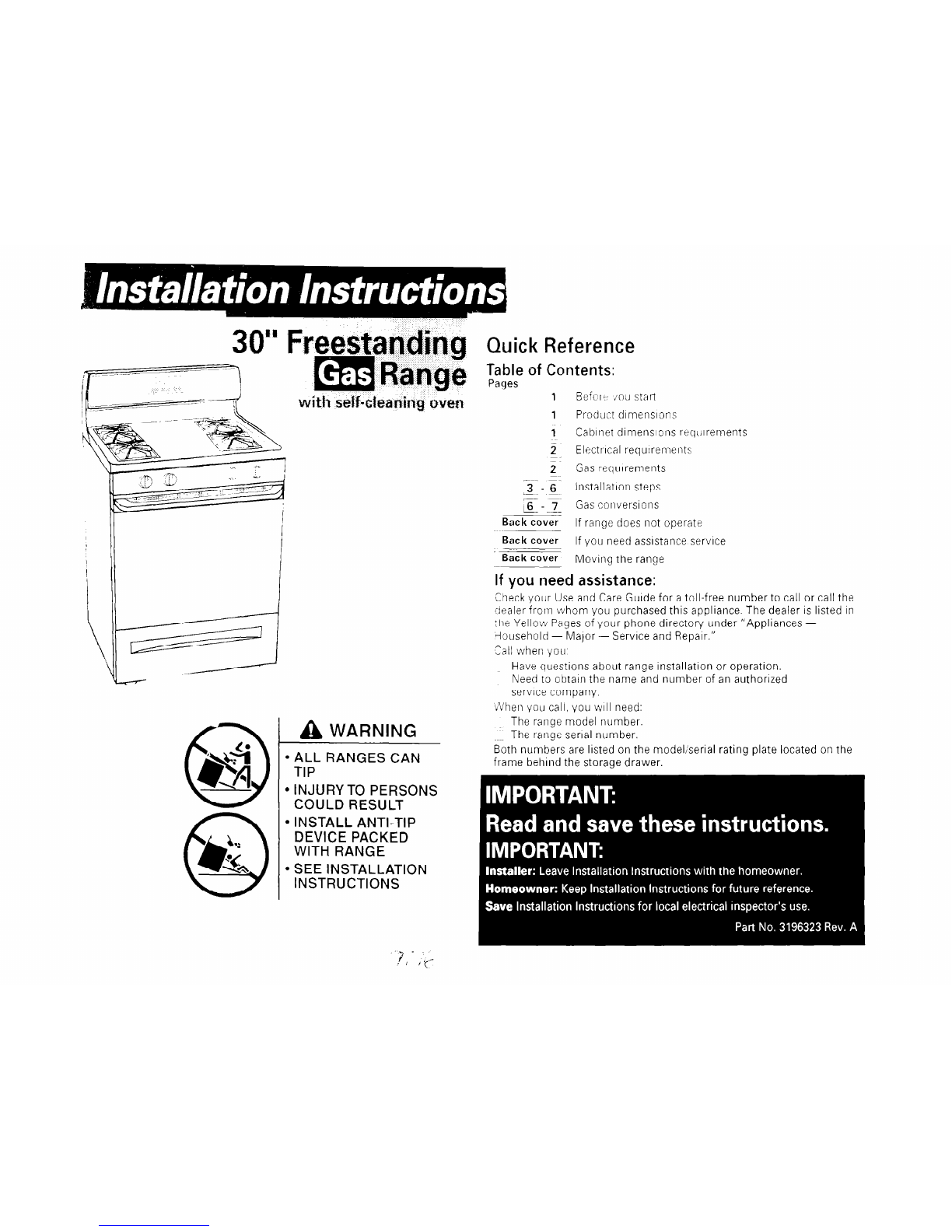
A WARNING
l
ALL RANGES CAN
TIP
l
INJURY TO PERSONS
COULD RESULT
l
INSTALL ANTI-TIP
DEVICE PACKED
WITH RANGE
l
SEE INSTALLATION
INSTRUCTIONS
,L. .
/
, , , y-
Quick Reference
Table of Contents:
Pages
1
Befcrr iou start
1
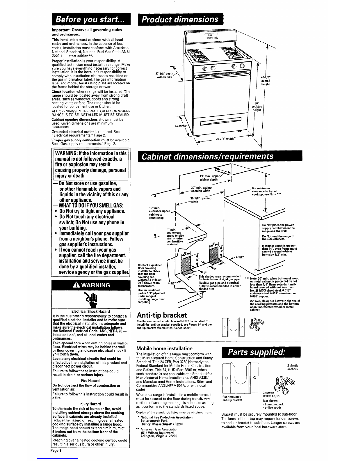
Product dlmenslons
1
Cabinet dimensions rtqlllrements
2 Electrical requlremeiits
2
Gas requirements
-~- ~.
2-- 6 Installation steps
&7
Gas conversions
Back cove7
If range does not operate
Back cover
If you need assistance service
Back cover
Moving the range
If you need assistance:
Check your Use and Care Guide for a toll-free number to call or call the
ilealer from Lvhorn you purchased this appliance. The dealer is listed in
:he Yellow Pages of your phone directory under “Appliances -
-lousehold - Major - Service and Repair.”
Call when you
Have questions about range installation or operation.
Need to obtain the name and number of an authorized
service company.
When you call, you will need:
The range model number.
~~~~The range serial number.
Both numbers are listed on the model/serial rating plate located on the
frame behind the storage drawer.
Important: Observe all governing codes
and ordinances.
This installation must conform with all local
codes and ordinances. In the absence of local
codes, installation must conform with American
National Standard, National Fuel Gas Code ANSI
2223.1 - latest edition**.
Proper installation is your responsibility. A
qualified technician must install this range. Make
sure you have everything necessary for correct
installation. It is the installer’s responsibility to
comply with installation clearances specified on
the gas information label. The gas information
label and model/serial rating plate are located on
the frame behind the storage drawer.
Check location where range will be installed. The
range should be located away from strong draft
areas, such as windows, doors and strong
heating vents or fans. The range should be
located for convenient use in kitchen.
ALL OPENINGS IN THE WALL OR FLOOR WHERE
RANGE IS TO BE INSTALLED MUST BE SEALED.
Cabinet opening dimensions shown must be
used. Given dimensions are minimum
clearances.
7
~ 29-7/W width
Grounded electrical outlet is required. See
“Electrical requirements,” Page 2.
Roper gas supply connection must be available.
See “Gas supply requirements,” Page 2.
WARNING:Iftheinformationinthis
manualis notfollowedexactly,a
fire orexplosionmayresult
causingpropertydamage,personal
injuryordeath.
- DoNotstoreorusegasoline,
orotherflammablevaporsand
liquidsinthevicinity ofthis oran\
otherappliance.
-WHAT TODOIFYOUSMELLGAS:
l
DoNottryto lightanyappliance.
l
DoNottouchanyelectrical
switch; DoNotuseanyphonein
yourbuilding.
l
Immediatelycall yourgassupplie
fromaneighbor’sphone.Follow
gassupplier’sinstructions.
l
Ifyoucannotreachyourgas
supplier,call thefire department.
- Installationandservicemustbe
donebyaqualifiedinstaller,
serviceagencyorthegassuppliei
30” min. cabinet
18” min.
For minimum
clearance to top of
cook-top, see Note.***
Do Not pinch the power
supply cord between the
range and the wall.
Do Not seal the range to
the side cabinets.
If cabinet depth is greater
than 24”. oven frame must
extend beyond cabinet
fronts by l/2” min.
wall or other
This shaded area reca
for installation of riqk
ea area.
T#mm*
f gas pipe. **+ Note: 30” min. when bottom of wood
electrical or metal cabinet is protected by not
rd in either less than l/4” flame retardant mill-
board covered with not less than
No. 28 MSG sheet steel, 0.015”
!ess steel, 0.024” aluminum or
outlet is recommende
stain1
0.020” copper.
Contact a qualified
floor covering
installer to check
that the floor
covering can
withstand at least
90°F above room
temperature.
Use an insulated
pad or 114” plywood
under range if
installing range over
carpeting. 36” min. clearance between the top of
the cooking platform and the bottom
of an unprotected wood or metal
Electrical Shock Hazard
It is the customer’s responsibility to contact a
qualified electrical installer and to make sure
that the electrical installation is adequate and
make sure the electrical installation follows
the National Electrical Code, ANSUNFPA 70 -
latest edition*, and all local codes and
ordinances.
Take special care when cutting holes in wall or
floor. Electrical wires may be behind the wall
or floor covering and cause electrical shock if
you touch them.
Locate any electrical circuits that could be
affected by the installation of this product and
disconnect power circuit.
Failure to follow these instructions could
result in death or serious injury.
Fire Hazard
Do Not obstruct the flow of combustion or
ventilation air.
Failure to follow this instruction could result in
3fire. Injury Hazard
‘o eliminate the risk of burns or fire, avoid
nstalling cabinet storage above the cooking
urface. If cabinets are already installed,
educe the hazard of reaching over a heated
:ooking surface by installing a range hood.
‘he range hood should extend a minimum of
i
inches out from the bottom front of the
:abinets.
leaching over a heated cooking surface could
esult in a serious burn or other injury.
Anti-tip bracket -
The floor-mount-ed anti-tip bracket MUST be installed. To
install the anti-tip bracket supplied, see Pages 3-4 and the
anti-tip bracket template/instruction sheet.
Mobile home installation
The installation of this range must conform with
the Manufactured Home Construction and Safety
Standard, Title 24 CFR,Part 3280 [formerly the
Federal Standard for Mobile Home Construction
and Safety, Title 24, HUD (Part 28011or, when
such standard is not applicable, the Standard for
Manufactured Home Installations, ANSI A225.1
and Manufactured Home Installations, Sites, and
Communities ANSI/NFPA 501A, or with local
codes.
When this range is installed in a mobile home, it
must be secured to the floor during transit. Any
method of securing the range is adequate as long
as it conforms to the standards listed above.
Copies of the standards listed may be obtained from:
* National Fire Protection Association
Batterymarch Park
Quincy, Massachusetts 02269
** American Gas Association
1515 Wilson Boulevard
Arlington, Virginia 22209
2 plastic
anchors
2 screw
I#lOx l-1/2”)
floor-mounted
anti-tip bracket Not shown:
- literature pack
- orifice spuds
Bracket must be securely mounted to sub-floor.
Thickness of flooring may require longer screws
to anchor bracket to sub-floor. Longer screws are
available from your local hardware store.
bge1
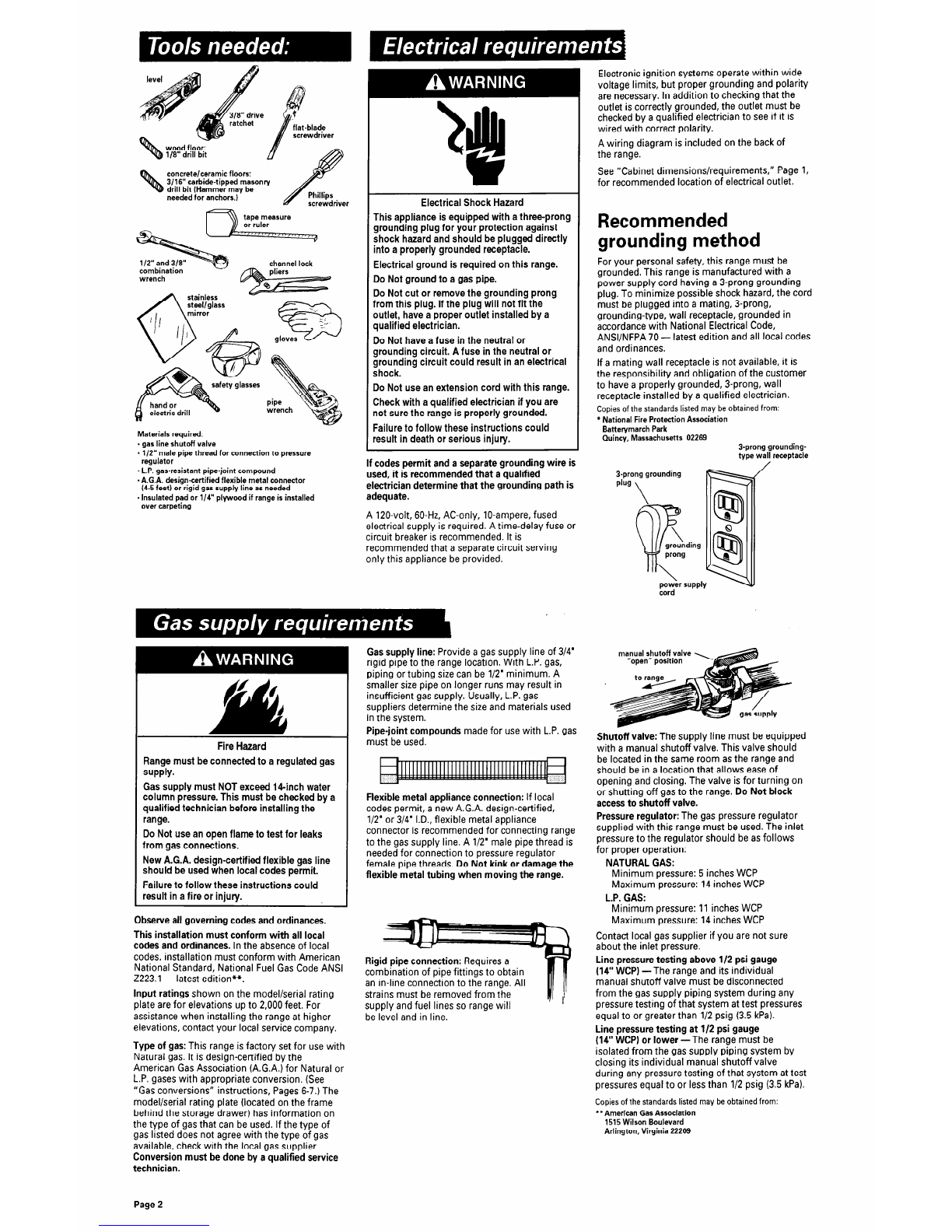
rarcnet flat-blade
screwdriver
wood floor:
l/8” drill bit
concrete/ceramic floors:
3/16” carbide-tipped masonry
’ drill bit (Hammer may be
needed for anchors.)
tape measure
or ruler
channel lock
combination
wrench
Materials required:
- gas line shutoff valve
- l/2” male pipe thread for connection to pressure
regulator
- L.P. gas-resistant pipe-joint compound
- A.G.A. design-certified flexible metal connector
(4-5 feet) or rigid gas supply line as needed
- Insulated pad or l/4” plywood if range is installed
over carpeting
Electrical Shock Hazard
This appliance is equipped with a three-prong
grounding plug for your protection against
shock hazard and should be plugged directly
into a properly grounded receptacle.
Electrical ground is required on this range.
Do Not ground to a gas pipe.
Do Not cut or remove the grounding prong
from this plug. If the plug will not fit the
outlet, have a proper outlet installed by a
qualified electrician.
Do Not have a fuse in the neutral or
grounding circuit. A fuse in the neutral or
grounding circuit could result in an electrical
shock.
Do Not use an extension cord with this range.
Check with a qualified electrician if you are
not sure the range is properly grounded.
Failure to follow these instructions could
result in death or serious injury.
If codes permit and a separate grounding wire is
used, it is recommended that a qualified
electrician determine that the grounding path is
adequate.
A 120-volt, 60-Hz, AC-only, IO-ampere, fused
electrical supply is required. A time-delay fuse or
circuit breaker is recommended. It is
recommended that a separate circuit serving
only this appliance be provided.
Fire Hazard
Range must be connected to a regulated gas
suPPlY-
Gas supply must NOT exceed 14-inch water
column pressure. This must be checked by a
qualified technician before installing the
range.
Do Not use an open flame to test for leaks
from gas connections.
New A.G.A. design-certified flexible gas line
should be used when local codes permit.
Failure to follow these instructions could
result in a fire or injury.
Observe all governing codes and ordinances.
This installation must conform with all local
codes and ordinances. In the absence of local
codes, installation must conform with American
National Standard, National Fuel Gas Code ANSI
2223.1 - latest edition**.
Input ratings shown on the model/serial rating
plate are for elevations up to 2,000 feet. For
assistance when installing the range at higher
elevations, contact your local service company.
Type of gas: This range is factory set for use with
Natural gas. It is design-certified by the
American Gas Association (A.G.A.) for Natural or
L.P. gases with appropriate conversion. (See
“Gas conversions” instructions, Pages 6-7.) The
model/serial rating plate (located on the frame
behind the storage drawer) has information on
the type of gas that can be used. If the type of
gas listed does not agree with the type of gas
available, check with the local gas supplier.
Conversion must be done by a qualified service
technician.
Gas supply line: Provide a gas supply line of 3/4’
rigid pipe to the range location. With L.P. gas,
piping or tubing size can be l/2’ minimum. A
smaller size pipe on longer runs may result in
insufficient gas supply. Usually, L.P. gas
suppliers determine the size and materials used
in the system.
Pipe-joint compounds made for use with L.P. gas
must be used.
Flexible metal appliance connection: If local
codes permit, a new A.G.A. design-certified,
l/2’ or 3/4’ I.D., flexible metal appliance
connector is recommended for connecting range
to the gas supply line. A l/2’ male pipe thread is
needed for connection to pressure regulator
female pipe threads. Do Not kink or damage the
flexible metal tubing when moving the range.
Rigid pipe connection: Requires a
combination of pipe fittings to obtain
an in-line connection to the range. All
strains must be removed from the
supply and fuel lines so range will
be level and in line.
Electronic ignition systems operate within wide
voltage limits, but proper grounding and polarity
are necessary. In addition to checking that the
outlet is correctly grounded, the outlet must be
checked by a qualified electrician to see if it is
wired with correct polarity.
A wiring diagram is included on the back of
the range.
See “Cabinet dimensions/requirements,” Page 1,
for recommended location of electrical outlet.
Recommended
grounding method
For your personal safety, this range must be
grounded. This range is manufactured with a
power supply cord having a 3-prong grounding
plug. To minimize possible shock hazard, the cord
must be plugged into a mating, 3-prong,
grounding-type, wall receptacle, grounded in
accordance with National Electrical Code,
ANSI/NFPA 70 - latest edition and all local codes
and ordinances.
If a mating wall receptacle is not available, it is
the responsibility and obligation of the customer
to have a properly grounded, 3-prong, wall
receptacle installed by a qualified electrician.
Copies of the standards listed may be obtained from:
* National Fire Protection Association
Batterymarch Park
Quincy, Massachusetts 02269 3-prong grounding-
type wall receptacle
3.prong grounding
plug
\
ding
power supply
&rd
manual shutoffvalve
‘open” posmon
Shutoff valve: The supply line must be equipped
with a manual shutoff valve. This valve should
be located in the same room as the range and
should be in a location that allows ease of
opening and closing. The valve is for turning on
or shutting off gas to the range. Do Not block
access to shutoff valve.
Pressure regulator: The gas pressure regulator
supplied with this range must be used. The inlet
pressure to the regulator should be as follows
for proper operation:
NATURAL GAS:
Minimum pressure: 5 inches WCP
Maximum pressure: 14 inches WCP
L.P. GAS:
Minimum pressure: 11 inches WCP
Maximum pressure: 14 inches WCP
Contact local gas supplier if you are not sure
about the inlet pressure.
Line pressure testing above l/2 psi gauge
(14” WCP) -The range and its individual
manual shutoff valve must be disconnected
from the gas supply piping system during any
pressure testing of that system at test pressures
equal to or greater than l/2 psig (3.5 kPa).
Line pressure testing at l/2 psi gauge
(14” WCP) or lower -The range must be
isolated from the gas supply piping system by
closing its individual manual shutoff valve
during any pressure testing of that system at test
pressures equal to or less than l/2 psig (3.5 kPa).
Copies of the standards listed may be obtained from:
l
* American Gas Association
1515 Wilson Boulevard
Arlington, Virginia 22209
Page 2
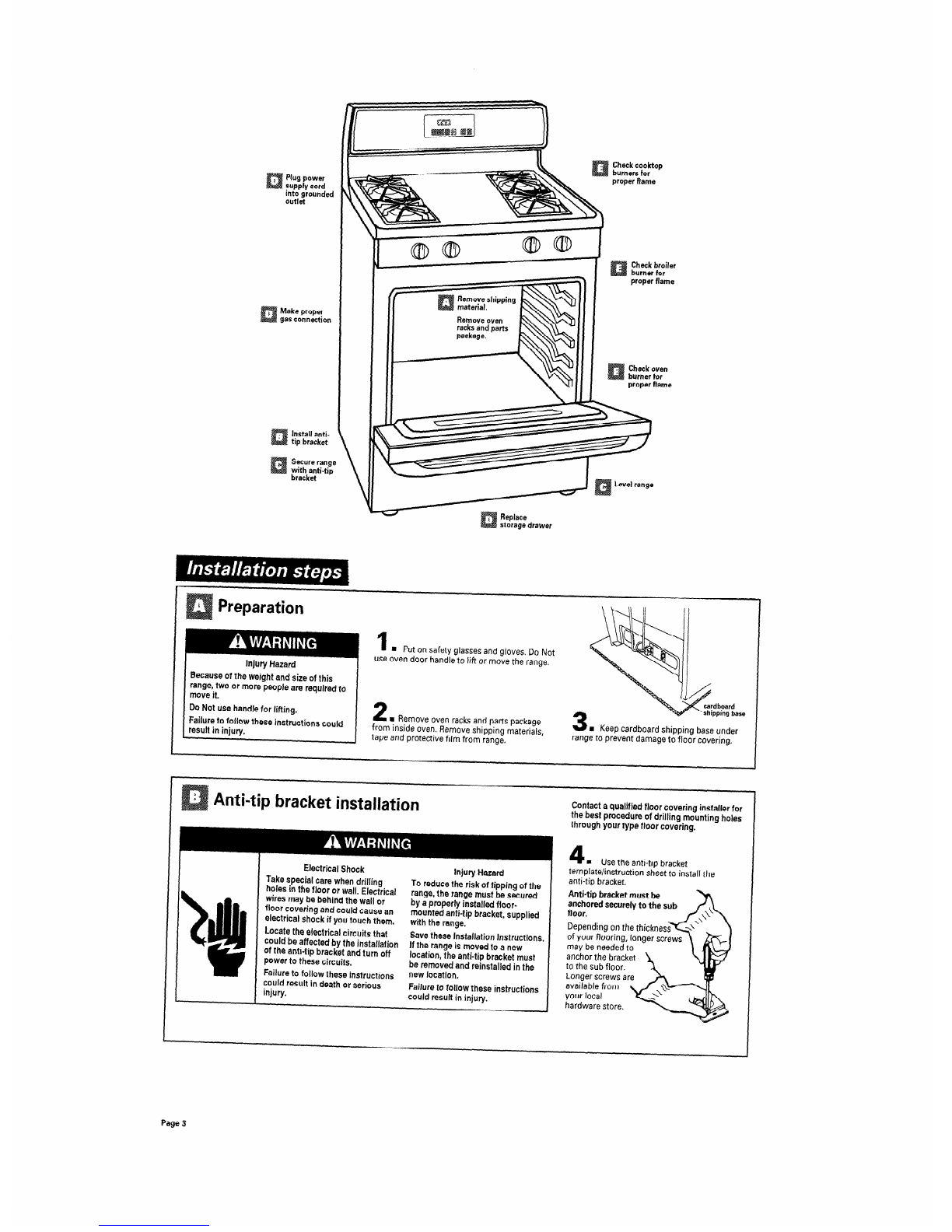
Check cooktop
burners for
proper flame
Plug power
supply cord
Into grounded
outlet
Check broiler
burner for
proper flame
Make proper
gas connection
Check oven
burner for
proper flame
Install anti-
tip bracket
Secure range
with anti-tip
bracket
Replace
storage drawer
Preparation
1
m Put on safety glasses and gloves. Do Not
use oven door handle to lift or move the range.
Injury Hazard
Because of the weight and size of this
range, two or more people are required to
move it.
Do Not use handle for lifting.
Failure to follow these instructions could
result in injury.
2
m Remove oven racks and parts package
from inside oven. Remove shipping materials,
tape and protective film from range.
3
a Keep cardboard shipping base under
range to prevent damage to floor covering.
Contact a qualified floor covering installer for
the best procedure of drilling mounting holes
through your type floor covering.
4
m Use the anti-tip bracket
Electrical Shock
Take special care when drilling
holes in the floor or wall. Electrical
wires
may
be behind the wall or
floor covering and could cause an
electrical shock if you touch them.
Locate the electrical circuits that
could be affected by the installation
of the anti-tip bracket and turn off
power to these circuits.
Failure to follow these instructions
could result in death or serious
injury.
Injury Hazard
To reduce the risk of tipping of the
range,
the range must be secured
by a properly installed floor-
mounted anti-tip bracket, supplied
with the range.
Save these Installation Instructions.
If the range is moved to a new
location, the anti-tip bracket must
be removed and reinstalled in the
new location,
Failure to follow these instructions
could result in injury.
templatelinstruction sheet to install the
anti-tip bracket.
Anti-tip
bracket must be
anchored securely to the sub
floor.
Depending on the thicknes
of your flooring, longer scre
may be needed to
anchor the bracket
to the sub floor.
Longer screws are
available from
your local
hardware store.
Page3
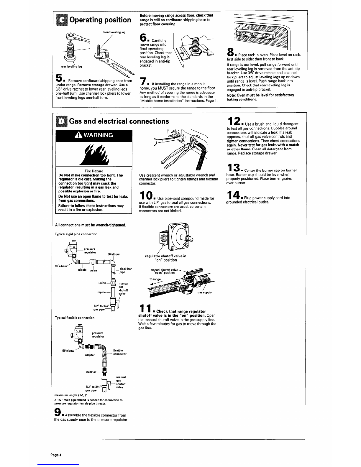
Operating position
Before moving range across floor, check that
range is still on cardboard shipping base to
protect floor covering.
under range. Remove storage drawer. Use a
3/8” drive ratchet to lower rear leveling legs
6
n
Carefully
move range into
final operating
position. Check that
rear leveling leg is
engaged in anti-tip
bracket.
7
n
If installing the range in a mobile
home, you MUST secure the range to the floor.
8
n
Place rack in oven. Place level on rack,
first side to side; then front to back.
If range is not level, pull range forward until
rear leveling leg is removed from the anti-tip
bracket. Use 3/8’ drive ratchet and channel
lock pliers to adjust leveling legs up or down
until range is level. Push range back into
position. Check that rear leveling leg is
engaged in anti-tip bracket.
one-half turn. Use channel lock pliers to lower Any method of securing the range is adequate
front leveling legs one-half turn. as long as it conforms to the standards in the Note: Oven must be level for satisfactory
“Mobile home installation” instructions, Page 1. baking conditions.
Gas and electrical connections
’ 0
Ak
f d
Fire Hazard
Do Not make connection too tight. The
regulator is die cast. Making the
connection too tight may crack the
regulator, resulting in a gas leak and
possible explosion or fire.
12
n
Use a brush and liquid detergent
to test all gas connections. Bubbles around
connections will indicate a leak. If a leak
appears, shut off gas valve controls and
tighten connections. Then check connections
again. Never test for gas leaks with a match
or other flame. Clean all detergent from
range. Replace storage drawer.
13
n
Center the burner cap on burner
Use crescent wrench or adjustable wrench and base. Burner cap should be level when
channel lock pliers to tighten fittings and flexible properly positioned. Place burner grates
connector. over burner.
Do Not use an open flame to test for leaks
from gas connections.
10
n
Use pipe-joint compound made for
14
n
Plug power supply cord into
Failure to follow these instructions may use with L.P. gas to seal all gas connections. grounded electrical outlet.
result in a fire or explosion. If flexible connectors are used, be certain
connectors are not kinked.
All connections must be wrench-tightened.
Typical rigid pipe connection
regulat shutoff valve in
“on” position
manual shutoff valve
“open” position
nipple - gas
shutoff
valve
l/2” to 314” k
/
gas pipe-
Typical flexible connection
pressure
regulator
11
n
Check that range regulator
shutoff valve is in the “on” position. Open
the manual shutoff valve in the gas supply line.
Wait a few minutes for gas to move through the
gas line.
aa I
adapter flexible
- connector
adapter - 4!
gas pipe
5
manual
9s
- shutoff
112” to 314” valve
maximum length 21-l/2”
A l/2” male pipe thread is needed for connection to
pressure regulator female pipe threads.
9
n
Assemble the flexible connector from
the gas supply pipe to the pressure regulator.
Page 4

Check operation
Electronic ignition system
Cooktop and oven burners use electronic
ignitors in place of standing pilots. When a
cooktop control knob is turned to the “LIGHT”
position, the system creates a spark to light
the burner. This sparking continues until the
control knob is turned to the desired setting.
When the oven control is turned to the desired
setting, a hot surface ignitor heats up bright
orange and ignites the gas. No sparking
occurs and the glow bar remains on while
the burners operate.
Check operation of cooktop
surface unit
control knob to “LIGHT” position. The flame
should light within 4 seconds. Turn control
knob to “HI” position after burner lights.
Do Not leave the knob in the “LIGHT”
position after burner lights.
Check each cooktop burner for
proper flame. The small inner cone
should have a very distinct blue
flame 1/4’to l/2’ long. The outer
cone is not as distinct as the inner
cone. If the flame is noisy or
blowing, it is getting too much air.
If the flame is soft and lazy, it is not getting
enough air. Turn surface burner control knobs
to “OFF” position. Adjust air shutter if needed.
If surface burners need adjusting:
1.Lift up cook-top maintop until it is held in
place by support rods.
r shutter
!.Adjust the air shutter for each burner by hand
as needed. Close the air shutter to decrease
the amount of air to the flame. Open the air
shutter to increase the amount of air to the
flame. Adjust the air shutterto the widest
opening that will not cause the flame to lift or
blow off of the burner.
3.Repeat the first part of Step 15 after adjusting
the air shutters.
You can check the burner flame by removing the
flame spreader or by using a mirror.
Remove flame spreader:
Remove two screws from the front tabs of the
flame spreader. Lift front of the flame spreader
and pull forward to remove tabs from rear of
oven.
Using a mirror:
Inset-t mirror to one side of the burner. Look into
mirror to check flame.
17
n
Follow the instructions for your type
of oven controls.
OFF “r”u”,,‘”
I .WARM
,
OVEN ON 0
(TURN OR OVEN WHEN FLASHING) CLEAN . :.... .. 200
OVEN HEATING 0 “,“,“O
@
“-..... :;-
‘.., ;. 250
BROIL . -.... :;:w
DOOR LOCKED/CLEANING 0
(CLOSEDOOR WeEN FLASHING)
‘-.. .-? l 300
..:...
, \. p
. .;.:y .
5oo , l . ;“.;. \
350
450 400
Push in and turn the oven selector control knob
to “350°F.” The oven burner should light in 5060
seconds; this delay is normal. The oven valve
requires a certain time before it will open and
allow gas to flow.
A
D i
1. Press the “BAKE” pad.
l
The “BAKE” indicator will light.
l
“35O’F” will appear in the display.
l
The “START?” indicator will begin to flash
after 5 seconds (console D only).
2. Press the START/ENTER pad.
9“PrE,” and “1O:OO”will appear in the
display.
l
“HEAT” and “ON” indicators will light.
l
The oven is preheated when the time in the
display counts down to “O:OO,”you hear a 1,
second tone, and “PrE” changes to “35O’F.”
To avoid damaging the hot surface ignitor,
do Not insert any object into the openings of
the protective shield that surrounds the ignitor
or clean that area.
3
n
Check the oven burner
for proper flame. The flame should be ‘I
l/2’ long, with inner cone of bluish-
green, and outer mantle of dark blue, ‘llm
and should be clean and soft in character. No
yellow tips, blowing or lifting of flame should
occur. If burner does not light, check that
the regulator shutoff valve is in the “on”
position (see Step 11I.
Check operation of oven burner
16
w Open oven door.
?emove oven bottom:
qemove two screws at the rear of the oven
lottom. Lift the rear of the oven bottom up and
lack until the front of the panel is away from
he front frame. Remove from oven.
B
If your oven has electronic control pads only:
1. Press the “BAKE” pad.
l
The “BAKE” indicator will light.
l
“350” will appear in the display.
l
The “START?” indicator will begin to flash
after 5 seconds.
2. Press the START/ENTER pad.
l
The “PREHEAT” or “HEAT,” and “ON”
indicators will appear.
l
The display will show the automatic
countdown time (IO minutes) needed to
preheat the oven for selected temperature.
l
The oven burner should light in 50-60
seconds; this delay is normal. The oven
valve requires a certain time before it will
open and allow gas to flow.
l
The oven is preheated when the “PREHEAT”
indicator light goes off (console A only), you
hear a l-second tone and the countdown
changes to “350”.
* Note: “PREHEAT” indicator light will not be
displayed if oven temperature is over 170°F.
and screw
If oven flame needs adjusting:
Remove storage drawer. Locate the air shutter
next to the pressure regulator. Loosen screw
and adjust the air shutter until the proper flame
appears. Tighten screw. Replace storage drawer.
19
n
Turn the control knob to “OFF” or
press the “OFF/CANCEL” pad.
20
n
Replace oven bottom, oven racks and
storage drawer.
Check operation of oven broil
burner
21
n
Follow the instructions for your
type of oven controls.
OVEN ON
l
iTVRNOFFOMNwHENRAs+lNG~ CLEAN.
OVEN HEATING 0 pg;;”
DOOR LOCKED/CLEANING 0 BROIL.
(CLCSEDOORWEN FLASHING)
Push in and turn the oven selector control knob
to “BROIL.” The broil burner should light in 50.
60 seconds; this delay is normal. The oven valve
requires a certain time before it will open and
allow gas to flow.
Page 5

Check operation
(cont.)
and screw-
If flame needs to be adjusted:
Loosen the lock screw on the air shutter
located at the rear of the broil burner.
Adjust the air shutter as needed.
Tighten lock screw.
1. Press the “CUSTOM BROIL” pad.
l
“HI” will appear in the display.
l
The “BROIL” indicator will light.
l
The ‘START?” indicator will begin to flash
after 5 seconds.
2. Press the “START/ENTER” pad.
l
“HEAT”and “ON” indicators will light.
l
The oven burner should light in 50-60
seconds; this delay is normal. The oven
valve requires a certain time before it will
open and allow gas to flow.
23
n
Turn the oven control knob to “OFF”
or press the “OFF/CANCEL” pad.
B
1. Press the “CUSTOM BROIL” pad.
l
“525” or “HI” will appear in the display.
*The “BROIL” indicator will light.
l
The “START?” indicator will begin to flash
after 5 seconds.
2. Press the “START/ENTER” pad.
l
“HEAT”(console B only) and “ON” indicators
will light.
l
The oven burner should light in 50-60
seconds; this delay is normal. The oven
valve requires a certain time before it will
open and allow gas to flow.
You have just finished installing
your new range. To get the most
efficient use from your range, read your
Use 81Care Guide.
Keep Installation Instructions and Guide
close to range for easy reference.
The instructions will make installing the
range in another home as easy as the
first installation.
w
n
Check the broil burner for
proper flame. The flame should be l/2’
long, with inner cone of bluish-green,
and outer mantle of dark blue. and mm’
should be clean and soft in character. No yellow
tips, blowing or lifting of flame should occur.
Gas conversions (from Natural oas to L.P. aas: or
from L.P. gas to Natural gas) m&t be do&by a
qualified installer.
pressure
regulator
air shutter
Fire Hazard
Shut off gas supply line valve.
Make all conversions before turning gas
supply valve back on.
Failure to follow these instructions could
result in explosion, fire or other injury.
pressure (
4
w Cooktop burners: Lift up cooktop
maintop until it is held in place by support rods.
Remove shipping screws from each burner.
Remove burners.
regulator
L.l? gas conversion
I
n
Complete installation sections A-C
(Pages 3-4) before converting cook-top to L.P.
gas. Check that main gas supply line has been
shut off and the power supply cord is
disconnected.
2
n
Remove storage drawer and oven racks.
Remove burner grates.
-was
Nat. gas L.P. gas
gas
manifold \
DO NOT REMOVE THE PRESSURE REGULATOR.
3
w Pressure regulator: Open plastic cover.
Turn cap marked “N” on front of pressure
regulator counterclockwise with a wrench to
remove. Do Not disturb or remove the spring
beneath the cap. Remove plastic cover, Turn the
L.R. L.F. R.F. RR.
cap over and reinstall plastic cover on top of cap.
Install cap on regulator so that the letters “L.P.”
are visible. Close plastic cover over cap.
5
w Locate L.P. gas orifice spuds in a
literature package included with the range.
Remove Natural gas orifice spuds using a 3/8’
combination wrench. Install L.P. gas orifice spud
to replace the Natural gas orifice spuds.
Place Natural gas orifice spuds in plastic parts
bag for future use and keep with literature
package. Reinstall burners. Lower maintop to
operating position. Reinstall burners and burner
grates.
Page 6

increase flame size
pre-set at factory
for Natural gas
6
n
Oven burner: Use l/2’ combination
wrench to turn the orifice hood down snug onto
pin (approximately 2 to 2-l/2 turns). DO NOT
OVERTIGHTEN. The burner flame cannot be
properly adjusted if this conversion is not made.
1
n
Broil burner: Use l/2’ combination
wrench to turn the orifice hood down snug onto
pin (approximately 2 to 2-l/2 turns). DO NOT
OVERTIGHTEN. The burner flame cannot be
properly adjusted if this conversion
is not made.
8
n
Reinstall the storage drawer. Complete
installation sections D through E, Pages 4-6.
Check for proper flame. The small inner cone
should have a very distinct blue flame l/4’ to l/2’
long. The outer cone is not as distinct as the
inner cone. L.P. gas flames have a slightly yellow
tip. If the flame is noisy or blowing, it is getting
too much air. If the flame is soft and lazy, it is not
getting enough air.
Natural gas conversion
1
H Complete installation sections A-C
(Pages 3-4) before converting cook-top to natural
gas. Check that main gas supply line has been
shut off and the power supply cord is
disconnected.
2
n
Remove storage drawer and oven racks.
Remove burner grates.
pressure
regulator <
Nat. gas L.P. gas
DO NOT REMOVE THE PRESSURE REGULATOR.
m Pressure regulator: Open plastic cover.
Turn cap marked “L.P.” on front of pressure
regulator counterclockwise with a wrench to
remove. Do Not disturb or remove the spring
beneath the cap. Remove plastic cover, Turn the
cap over and reinstall plastic cover on top of cap.
Install cap on regulator so that the letter “N” is
visible. Close plastic cover over cap.
TJi pping screw
air shutter
4
n
Cooktop burners: Lift up cook-top
maintop until it is held in place by support rods.
Remove shipping screws from each burner.
L.R. L.F. R.F. RR.
5
n
Locate Natural gas orifice spuds in
literature package. Remove L.P. gas orifice spuds
using a 3/V combination wrench. Install Natural
gas orifice spuds.
Place L.P. gas orifice spuds in plastic parts bag
for future use and keep with literature package.
Lower maintop to operating position and
reinstall burners and burner grates.
N
in
in
pre-set at factory
for Natural gas
6
n
Oven burner: Use l/2’ combination
wrench to loosen the orifice hood away from pin
(approximately 2 to 2-l/2 turns). The burner
flame cannot be properly adjusted if this
conversion is not made.
7
n
Broil burner: Use l/2’ combination
wrench to loosen orifice hood away from pin
(approximately 2 to 2-l/2 turns). The burner
flame cannot be properly adjusted if this
conversion is not made.
8
n
Reinstall the storage drawer. Complete
installation sections D through E, Pages 4-6.
Check for proper flame. Natural gas flames do
not have yellow tips.
Page 7

If range does not operate:
VJ Check that the circuit breaker is not tripped
or the house fuse blown.
q
Check that the power supply cord is plugged
into the wall receptacle.
q
Check that gas line is turned on.
q
See Use and Care Guide for troubleshooting list.
If you need assistance:
If you have questions about operating, cleaning
or maintaining your range:
q
Refer to Use and Care Guide.
Qj Call the Consumer Assistance Center. Check
your Use and Care Guide for a toll-free
number to call or call the dealer from whom
you purchased this appliance. The dealer is
listed in the Yellow Pages of your phone
directory under “Appliances -Household -
Major-Service and Repair.”
If you need service:
Maintain the quality built into your range by
calling an authorized service company.
To obtain the name and number of an
authorized service company:
1 Contact the dealer from whom you
purchased your range; or
q
Look in the Yellow Pages of your telephone
directory under “Appliances -Household -
Major-Service and Repair;” or
q
Call the Consumer Assistance Center.
The toll-free number is listed in your Use
and Care Guide.
When you call, you will need:
q
The range model number.
q
The range serial number.
Both numbers are listed on the model/serial
rating plate located on the frame behind the
storage drawer.
Part No. 3196323 Rev. A
0 1996
Moving the range:
Injury Hazard
l Because of the weight and size of this range,
two or more people are required to move it.
l All ranges can tip.
l Do Not step, lean or sit on the range drawer
or door.
*The anti-tip device packed with range must
be installed. See Installation Instructions.
Failure to follow these instructions could
result in injury.
Benton Harbor, Michigan 49022
When moving range, slide range onto cardboard
or hardboard to prevent damaging the floor
covering.
If removing the range is necessary for cleaning
or maintenance:
1. Remove the storage drawer.
2. Shut off the gas supply to the range.
3. Disconnect gas and electrical supplies. If
necessary, pull the range out, away from the
wall, just far enough to disconnect the gas and
electric supply lines,
4.
Remove range to complete cleaning or
maintenance.
5. Move range back into operating position. Look
underneath range (a flashlight may be needed)
to check that leg is engaged in anti-tip bracket.
If leg is not properly engaged, remove and
reposition bracket to insure that leg fits
properly in bracket.
6. Check that range is level
7. Reconnect gas line to range and check for
leaks.
8. Plug power supply cord into outlet. Reinstall
storage drawer.
Printed in U.S.A.
This manual suits for next models
1
Table of contents
Other Benton Harbor Range manuals

Popular Range manuals by other brands


Frigidaire
Frigidaire 316423411 Use & care manual

Falcon
Falcon Classic 90 Gas Instructions for use and installation

Danby
Danby DRCA240BSS2 owner's manual

GE
GE JB250RFSS Dimensions and installation information

Hotpoint
Hotpoint AQUARIUS+ WF645 Instructions for installation & use

LG
LG LRE3021ST owner's manual