Benton Harbor Michigan 49022 User manual
IMPORTANT:
Read and save
these instructions. 30” Freestanding
m Range
Part No. 76948-00/4363032
IMPORTANT:
Installer: Leave Installation Instructions with
the homeowner.
Homeowner: Keep Installation Instructions
for future reference.
Save Installation Instructions for local
electrical inspector’s use.

Before vou start...
Check location where range will be
installed. The range should be located
WARNING: If the information
in this manual is not
followed exactly, a fire or
explosion may result
causing property damage,
personal injury or death.
- Do Not store or use
gasoline or other
flammable vapors and
liquids in the vicinity of
this or any other
appliance.
- WHAT TO DO IF YOU SMELL
GAS
l
Do Not try to light any
appliance.
l
Do Not touch any
electrical switch; Do Not
use any phone in your
building.
l
Immediately call your
gas supplier from a
neighbor’s phone.
Follow gas supplier’s
instructions.
l
If you cannot reach your
gas supplier, call the fire
department.
- Installation and service
must be performed by a
qualified installer, service
agency or the gas
supplier.
&
Proper installation isyour responsibility. Make
sure you have everything necessary for correct
installation. It isthe responsibility of the installer
away from strong draft areas, such as
windows, doors and strong heating vents
or fans. The range should be located for
convenient use in the kitchen. Recessed
to comply with the installation clearances
specified on the serial/rating plate. The
serial/rating plate islocated under the maintop.
Important: Observe all governing
codes and ordinances. Failure to
meet codes and ordinances
could lead to fire or electrical
shock hazard.
installation must provide complete
enclosure of the sides and rear of range.
.
Cabinet opening dimensions that
are shown must be used. Given
1 dimensions provide 0” clearance.
Grounded electrical
outlet isrequired. See
Electrical requirements.
Proper gas supply
connection must be
available. See Gas
supply requirements.
J
For minimum
clearances,
see Note.“’
4’ min.
countertop
space to side
ALL OPENINGS IN
wall or other
combustible
material.
,/ IH’\A/Al I CTD
L ““r\LL “1.
t~00R WHERE
THERANGE ISTO
BEINSTALLED
MUSTBESEALED.
18” min. clearance
upper cabinet
to countertop
/------
30-l 14”
opening
width
I
i
center of
i
range
i ’
wall gas line’
opening -
3” min. 4” max.
from left side of
cabinet
4” 7’ or 9” backguard
I
YF-
.
overall
height
36”
cooktop
height
27-t 14”
depth with
handle
Do Not pinch the
power cord
between the range
and wall.
Do Not seal range
to the side cabinets. Oven frame must
extend beyond
cabinet lronts
by l/2”.
Electrical Shock Hazard
0Take special care when cutting holes
in wall. Electrical wires may be
concealed behind the wall covering
and contact with them could result in
electrical shock.
l
locate any electrical circuits that
could be affected by the installation
of this product and disconnect
power circuit.
Failure to do so could result in
electrical shock.
NOTE:(
Clearances specified are for
\
24”
Fire Hazard
Do Not obstruct the flow of
combustion and ventilation air.
Personal Injury Hazard
Avoid installing cabinet storage
above the cooking surface. If
cabinets are already installed, reduce
the hazard of reaching over a heated
cooking surface by installing a range
hood. The range hood should extend
a minimum of 5 inches out from the
bottom front of the cabinets.
Reaching over a heated cooking
surface could result in a serious burn
or other personal injury.
Electrical Shock Hazard
It is the customer’s responsibility:
l
To contact a qualified electrical
installer.
l
To assure that electrical installation
is adequate and in conformance
with National Electrical Code,
ANSI/NFPA 70-latest edition,* and
all local codes and ordinances.
Failure to do so could result in fire,
electrical shock or other personal
injury.
***Note: 30” min. when bottom of
wood or metal cabinet is protected
by not less than l/4” flame
retardant millboard covered with
not less than No. 28 MSG sheet
steel,.O.OlS” stainless steel, 0.024”
alumrnum or 0.020” copper.
36” min. clearance between the
top of the cooking platform and
the bottom of an unprotected
wood or metal cabinet.
combustible walls and materials that have
a density of 20 or more pounds per cubic
foot. No evaluation of clearances has
been made for installation adiacent to
materials that are lessthan 20*pounds per
cu. ft. or to plastic tiles and sheeting.
Tools needed for
Mobile home installation
The installation of this range must
conform to the Manufactured Home
Construction and Safety Standards, Title
24 CFR, Part 3280 (formerly the Federal
Standard for Mobile Home Construction
and Safety, Title 24, HUD Part 280) or
when such standard is not applicable,
the Standard for Manufactured Home
Installation 1982 (Manufactured Home
Sites, Communities and Setups), ANSI
2225.1-1987, or latest edition, or with
local codes.
When this range isinstalled in a mobile
home, it must be secured to the floor
during transit. Any method of securing
the range isadequate as long as it
conforms to the standards listed above.
Copies of the standards listed may be
obtained from:
l
National Fire Protection Association
Batterymarch Park
Quincy, Massachusetts 02269
**American Gas Association
1515 Wilson Boulevard
Arlington, Virginia 22209
tnstaffatton:
. hand or eleclrlc
drill
. concrele/ceramlc Iloors:
l/4’
masonry
drill bit
. wood floors: l/8’ drill bit
. gas line shutoff valve
. L,P.-reslslanl plpe-Joint compound
. AGA deslgn-cetlilied flexible metal connector (4-5 Ieel)
Property Damage
l
Contact a qualified floor covering
installer to check that the floor
covering can withstand heat at least
90°F above room temperature.
l
Use an insulated pad or l/4”
plywood under range if installing
range over carpeting.
Failure to do so may result in damage
to floor covering.
Panel A

Gas supply
requirements
Observe all governing codes and
ordinances.
Fire Hazard
l
Range must be connected to a
regulated gas supply.
l
L.P.gas supply must Not
exceed a pressure of 14” water
column. This must be checked by
a qualified technician before
installing this range.
l
Do Not use an open flame to
test for leaks from gas
connections.
l
New, A.G.A. design-certified
flexible gas line should be used
when local codes permit.
Failure to follow these instructions
could result in a fire, explosion or
personal injury.
A.
This installation must conform with local
codes and ordinances. In the absence
of local codes, installations must
conform with American National
Standard, National Fuel Gas Code ANSI
Z223.1-latest edition‘*.
B
n
Input ratings shown on the serial/rating
plate are for elevations up to 2,000 feet.
For elevations above 2,000 feet, ratings
are reduced at a rate of 4% for each
1,000 feet above sea level.
C
This r&ge isequipped for use with
NATURALgas. It isdesign-certified by
A.G.4. for NATURALand L.P.gases with
appropriate conversion, The
serial/rating plate, located under the
maintop, has information on the type of
gas that can be used. If this information
does not agree with the type of gas
available, check with the local gas
supplier. See Panel Efor L.P. gas
conversion instructions.
D.
Provide a gas supply line of 3/4” rigid
pipe to the range location. A smaller
size pipe on long runs may result in
insufficient gas supply. Pipe-joint
compounds made for use with L.P.gas
must be used. With L.P.gas, piping or
tubing size can be l/2” minimum. L.P.
gas suppliers usually determine the size
and materials used on the system.
t n
If local codes permit, a new, A.G.A.
design-certified, 4-5 foot long, l/2” or 3/4”
I.D., flexible metal appliance connector is
recommended for connecting this range
to the gas supply line. Do Not kink or
damage the flexible tubing when moving
the range. A l/2” male pipe thread is
needed for connection to pressure
regulator female pipe threads.
F.
The supply line shall be equipped with
an approved shutoff valve. This valve
should be located in the same room as
the range and should be in a location
that allows ease of opening and
closing. Do Not block access to shutoff
valve.
G
If rigid’pipe isused as a gas
supply line, a combination of
pipe fittings must be used to
obtain an in-line connection to the
range. All strains must be removed
from the supply and fuel lines so
range will be level and in line.
H.
The inlet pressure to the regulator should
be as follows for both operation and
checking regulator setting:
NATURALGAS:
Set pressure 6 inches
Maximum inlet pressure 14 inches
L.P.GAS:
Set pressure 11 inches
Maximum inlet pressure 14 inches
I wLine pressure testing:
Testing above l/2 lb psi (gauge)
The range and its individual shutoff
valve must be disconnected from the
gas supply piping system by closing its
individual manual shutoff valve during
any pressure testing of the gas supply
piping system at test pressures equal to
or greater than l/2 psig (3.5 kPa).
Testing at l/2 lb psi (gauge)
The range must be isolated from the
gas supply piping system by closing its
individual manual shutoff valve during
any pressure testing of the gas supply
piping system at test pressures equal to
or lessthan l/2 psig (3.5 kPa).
Electrical
requirements
Electrical Shock Hazard
l
Electrical ground is required on
this appliance.
l
If cold water pipe is interrupted
by plastic, non-metallic gaskets
or other insulating materials, Do
Not use for grounding.
l
Do Not ground to a gas pipe.
l
Do Not modify the power supply
cord plug. If it does not fit the
outlet, have a proper outlet
installed by a qualified
electrician.
l
Do Not have a fuse in the
neutral or grounding circuit. A
fuse in the neutral or grounding
circuit could result in electrical
shock.
l
Do Not use an extension cord
with this appliance.
l
Check with a qualified
electrician if you are in doubt as
to whether the appliance is
properly grounded.
Failure to follow these instructions
could result in serious injury or
death.
If codes permit and a separate
grounding wire is used, it is
recommended that a qualified
electrician determine that the
grounding path is adequate.
A 120-volt, 60-Hz, AC-only, 15ampere,
fused electrical supply isrequired. A
time-delay fuse or circuit breaker is
recommended. It isrecommended that
a separate circuit serving only this
appliance be provided.
Electronic ignition systems operate
within wide voltage limits, but proper
grounding and polarity are necessary.
In addition to checking that the outlet
provides 120-volt power and iscorrectly
grounded, the outlet must be checked
by a qualified electrician to see if it is
wired with correct polarity.
A wiring diagram is included in the
literature package. The wiring diagram
isalso located on the back of the
range.
Recommended
grounding method
For your personal safety, this appliance
must be grounded. Thisappliance is
manufactured with a power supply
cord having a 3-prong grounding plug.
To minimize possible shock hazard, the
cord must be plugged into a mating, 3-
prong, grounding-type, wall
receptacle, grounded in accordance
with the National Electrical Code,
ANSI/NFPA 70-latest edition*, and all
local codes and ordinances. (See
Figure 1.) If a mating wall receptacle is
not available, it isthe personal
responsibility and obligation of the
customer to have a properly grounded,
3-prong, wall receptacle installed by a
qualified electrician.
J-prong
grounding-type
wall receptacle
supply cord
Figure 1
Panel B
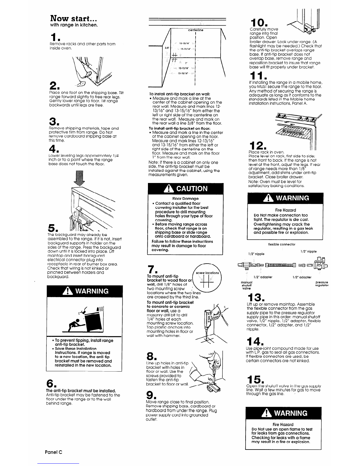
Now start...
with range in kitchen.
1
n
Remove racks and other parts from
inside oven.
2
n
Place one foot on the shipping base. Tilt
range forward slightly to free rear legs,
Gently lower range to floor. Tilt range
backwards until legs are free.
3
Rem:ve shipping materials, tape and
protective film from range. Do Not
remove cardboard shipping base at
this time.
4
LowE leveling legs approximately l/4
inch or to a point where the range
base does not touch the floor.
5 1
The backguard may already be
assembled to the range. If it isnot, insert
backguard supports in holder on the
sides of the range. Pressthe backguard
down until it islocked into place. Lift
maintop and insert backguard
electrical connector plug into
receptacle in rear of burner box area.
Check that wiring isnot kinked or
pinched between holders and
backguard.
l
To prevent tipping, install range
anti-tip bracket.
l
Save these Installation
Instructions. If range is moved
to a new location, the anti-tip
bracket must be removed and
reinstalled in the new location.
6.
The anti-tip bracket must be installed.
Anti-tip bracket may be fastened to the
floor under the range or to the wall
behind range.
centerline
J/8’ -
1%13/16’
i
+I-
i
ff‘ ,. i\
1%WI6
-i
13-15/16
i
i
i
i
To install anti-tip bracket on wall:
l
Measure and mark a line at the
center of the cabinet opening on the
rear wall. Measure and mark lines 12-
13/16” and 13-15/16” from either the
left or right side of the centerline on
the rear wall. Measure and mark on
the rear wall a line S/8” from the floor.
To install anti-tip bracket on floor:
l
Measure and mark a line in the center
of the cabinet opening on the floor.
Measure and mark lines 12-13/16’
and 13-15/l 6’ from either the left or
right side of the centerline on the
floor. Measure and mark on the floor
1” from the rear wall.
Note: If there isa cabinet on only one
side, the anti-tlp bracket must be
installed against the cabinet, using the
measurements given.
Floor Damage
l
Contact a qualified floor
covering installer for the best
procedure to drill mounting
holes through your type of floor
covering.
l
Before moving range across
floor, check that range is on
shipping base or slide range
onto cardboard or hardboard.
Failure to follow these instructions
may result in damage to floor
covering.
screw locations
To mount anti-tip
bracket to wood floor or
wall, drill l/8’ holes at
two mounting screw
locations where the twdlines
are crossed by the third line.
To mount anti-tip bracket
to concrete or ceramic
floor or wall, use a
masonry drill bit to drill
l/4” holes at each
mounting screw location.
Tap plastic anchors into
mounting holes in floor or
wall with hammer.
8 1
Line up holes in anti-tip
bracket with holes in
floor or wall. Use the
screws provided to
fasten the anti-tip
bracket to floor or wall
9w
Move range close to final position.
Remove shipping base, cardboard or
hardboard from under the range. Plug
power supply cord into grounded
outlet.
10
Carefull;move
ranae into final
pos%on. Open
broiler drawer. Look under range. (A
flashlight may be needed.) Check that
the anti-tip bracket overlaps range
base. If anti-tip bracket does not
overlap base, remove range and
reposition bracket to insure that range
base will fit properly under bracket.
11.
If installing the range in a mobile home,
you MUSTsecure the range to the floor.
Any method of securing the range is
adequate as long as it conforms to the
standards listed in the Mobile home
installation instructions, Panel A.
Place rack in oven.
Place level on rack, first side to side;
then front to back. If the range isnot
level at the front, adjust the legs. If rear
of range needs more than l/8”
adjustment, add shims under anti-tip
bracket. Close broiler drawer.
Note: Oven must be level for
satisfactory baking conditions.
Fire Hazard
Do Not make connection too
tight. The regulator is die cast.
Overtightening may crack the
regulator, resulting in a gas leak
and possible fire or explosion.
flexible connector
l/2” nipple l/2” nipple
I/2” adapter l/2” adapter
manual pressure
shutoff regulator
valve
13 w
Lift up or remove maintop. Assemble
the flexible connector from the gas
supply pipe to the pressure regulator
supply pipe in this order: manual shutoff
valve, l/2” nipple, l/2” adapter, flexible
connector, l/2’ adapter, and l/2”
nipple.
14 1
Use pipe-joint compound made for use
with L.P.gas to seal all gas connections.
If flexible connectors are used, be
certain connectors are not kinked.
15.
Open the shutoff valve in the gas supply
line. Wait a few minutes for gas to move
through the gas line. ’
Fire Hazard
Do Not use an open flame to test
for leaks from gas connections.
Checking for leaks with a flame
may result in a fire or explosion.
Panel C
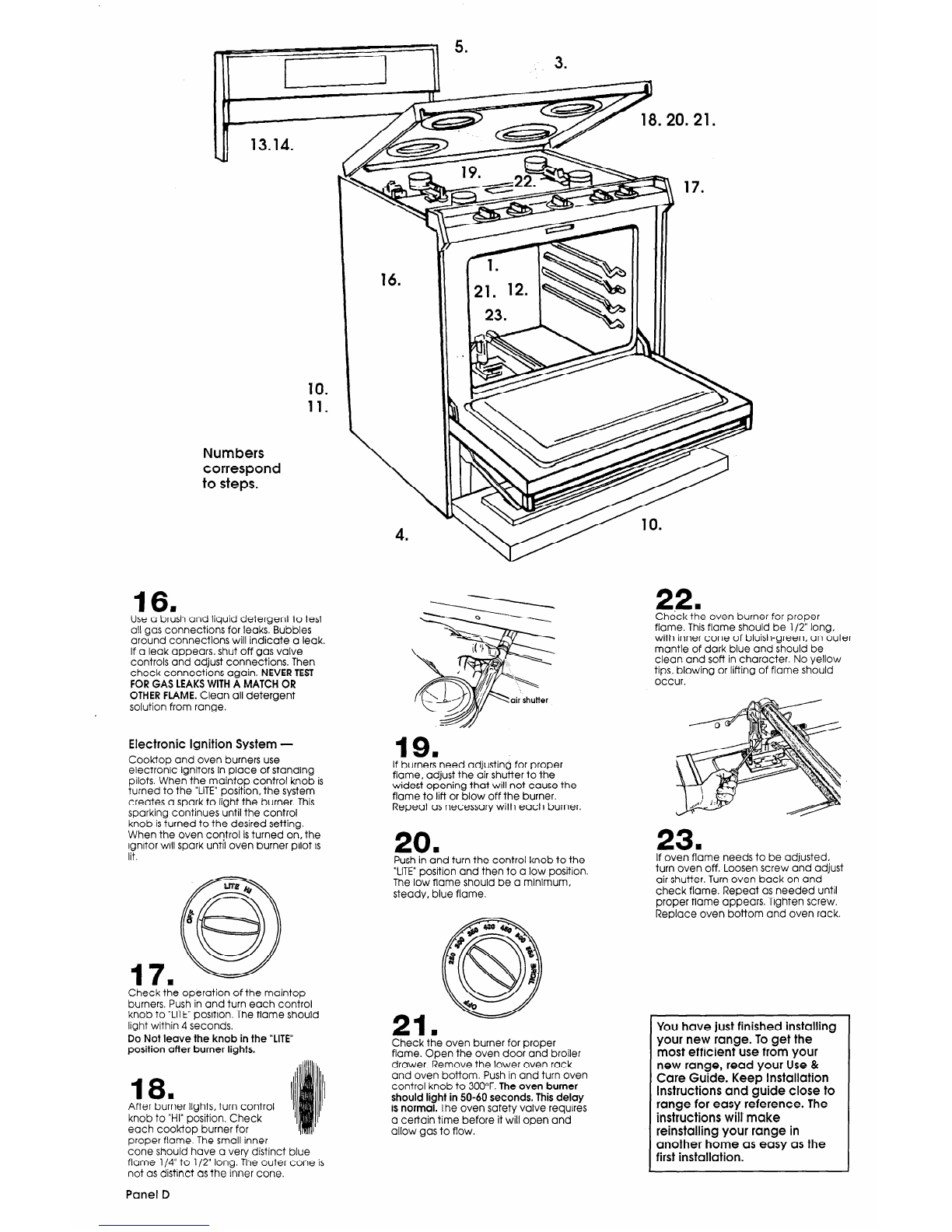
16
m
Use a brush and liquid detergent to test
all gas connections for leaks. Bubbles
around connections will indicate a leak.
If a leak appears, shut off gas valve
controls and adjust connections. Then
check connections again. NEVERTEST
FORGAS LEAKSWITHA MATCH OR
OTHERFLAME.Clean all detergent
solution from range.
Numbers
correspond
to steps.
Electronic Ignition System -
Cooktop and oven burners use
electronic ignitors in place of standing
pilots. When the maintop control knob is
turned to the “LITE”position, the system
creates a spark to light the burner. This
sparking continues until the control
knob isturned to the desired setting.
When the oven control isturned on, the
ignitor will spark until oven burner pilot is
lit.
Check the operation of the maintop
burners. Push in and turn each control
knob to “LITE”position. The flame should
light within 4 seconds.
Do Not leave the knob in the “LITE”
position after burner lights.
18
After buter lights, turn control
knob to “HI” position. Check
each cooktop burner for
proper flame. The small inner
cone should have a very distinct blue
flame l/4” to l/2” long. The outer cone is
not as distinct as the inner cone.
19 w
If burners need adjusting for proper
flame, adjust the air shutter to the
widest opening that will not cause the
flame to lift or blow off the burner.
Repeat as necessary with each burner.
Push in and turn the control knob to the
20
“LITE”position and then to a low position.
n
The low flame should be a minimum,
steady, blue flame.
Check the oven burner for proper
flame. Open the oven door and broiler
drawer. Remove the lower oven rack
and oven bottom. Push in and turn oven
control knob to 300°F. The oven burner
should light in SO-60seconds. This delay
is normal. The oven safety valve requires
a certain time before it will open and
allow gas to flow.
22.
Check the oven burner for proper
flame. Thisflame should be l/2” long,
with inner cone of bluish-green, an outer
mantle of dark blue and should be
clean and soft in character. No yellow
tips, blowing or lifting of flame should
occur.
If oven flame needs to be adjusted,
turn oven off. Loosen screw and adjust
air shutter. Turn oven back on and
23.
check flame. Repeat as needed until
proper flame appears. Tighten screw.
Replace oven bottom and oven rack.
You have just finished installing
your new range. To get the
most efficient use from your
new range, read your Use &
Care Guide. Keep Installation
Instructions and guide close to
range for easy reference. The
instructions will’ make
reinstalling your range in
another home as easy as the
first installation.
Panel D

L.F!
gas
conversion
Fire Hazard
l
Locate gas supply valve between
pressure regulator and gas valve.
Shut off gas supply valve in range
before converting to L.P.gas.
l
Make all maintop and oven
burner conversions before turning
gas supply valve back on.
Failure to follow these instructions
could result in fire, explosion or
other personal injury.
Converting to L.P. gas
Converting to L.P.gas should be done
by a qualified installer.
A
n
Complete installation Steps 1-12 before
converting your range to L.P.gas.
Remove oven racks and oven bottom.
Open broiler drawer. Shut off gas supply
valve in range. Remove burner grates
and carefully lift up or remove maintop.
Pressure regulator:
Use a wrench to unscrew the cap from
the top by turning counterclockwise.
Turn the cap over so the hole end isup.
Replace the cap and gasket on the
regulator. DO NOT REMOVETHE
PRESSUREREGULATOR.
D.
Oven burner:
Turn the orifice hood down
snug onto pins (approximately 2 to 2-l /2
turns.) DO NOT OVERTIGHTEN.The
burner flames cannot be properly
adjusted if this conversion isnot made.
E
Afteryhe burners have been converted
to L.P.gas usage, complete Steps 13-16,
Panels C and D.
Adjusting for proper flame
Cooktop burners:
Adjust the air shutters for proper flame
by sliding the air shutter to close or
open the shutter as needed. See Panel
D, Steps 17-20. L.P.gas has a slightly
yellow tip on top of burner flames in
addition to the other proper
characteristics.
B.
Oven burners:
Adjust the air shutters as needed for
proper flame. See Panel D, Steps 2l-23.
C
Rep&e oven bottom and oven racks.
Reinstall the maintop and burner grates.
C
Cookyop burners:
Turn the orifice hoods down
snug onto pins (approximately 2 to 2-l/2
turns.) DO NOT OVERTIGHTEN.The
burner flames cannot be properly
adjusted if this conversion isnot made.
Panel E

If range does not
operate...
l
Check that the circuit breaker is
not tripped or the house fuse blown.
l
Check that power supply cord is
plugged into wall receptacle.
l
Check that the gas supply isturned
on.
NOTE:
Refer to Use and Care Guide for
opero-ting instructions and cleaning
instructions.
Personal Injury/
Product Damage Hazard
Do Not step, lean or sit on ttie range
drawer or door.
Failure to follow these instructions
could result in personal injury
and/or product damage.
For cleaning and
maintenance...
If removing the range is necessary for
cleaning and maintenance, shut off
gas supply to the range. Disconnect the
gas and electrical supply.
If the gas or electrical supply is
inaccessible, lift the range slightly at the
front
and pull the range away from the
wall. Pull the range out only as far as
necessary to disconnect the gas and
electric supply lines.
Remove the range to complete
cleaning or maintenance.
Move range back into operating
position. Level the range. Connect the
gas line to the range and check for
leaks. Plug electric power supply cord
into outlet.
Make sure the anti-tip bracket overlaps
range base.
If you need
assistance...
Check your Use and
Care Guide for a
toll-free number to call, or call the
dealer from whom you purchased this
appliance. The dealer islisted in the
Yellow Pages of your phone
directory
under “Appliances - major.”
When you call, you will need the range
model number and serial
number. Both
numbers can be found on the
serial/rating plate located
under the
maintop.
Part No. 76948-OOl4363032
0 1992 Benton Harbor, Michigan 49022 Printed in U.S.A.
Table of contents
Other Benton Harbor Range manuals

Popular Range manuals by other brands

Maytag
Maytag MGR5875QDW - 30 Inch Gas Range Use and care guide

Frigidaire
Frigidaire FFGF3024SS use & care

Capital
Capital Precision Series GCR484W Specifications

Officine Gullo
Officine Gullo GGS8P Installation and use instruction

LG
LG LSD4913 Series owner's manual

Kenmore
Kenmore 4101 - Elite 30 in. Slide-In Electric Range installation instructions


