Bergen INTREPID GAS User manual

95

94
There are two more adjustments to make on your new Intrepid. These are the tail
rotor and the throttle. With the radio turned on and the tail rotor in neutral (if you have tail
compensation turned on, make sure that the collective is also in neutral), position the tail
rotor servo arm one spline ahead of the position that would have the ball vertically
positioned. Now connect the pushrod to the servo, and adjust it’s length so that there is
approximately 5 to 10 degrees of positive pitch in the tail rotor. (“Positive” pitch in the tail
rotor is in the direction so as to make the tail rotor blow air to the right of the helicopter
when it is rotating.) The length of the servo arm should be made such that with full
movement in each direction a very slight binding occurs in the pitch slider on the tail
rotor output shaft. This binding will never occur in flight, as the gyro will decrease the
available movement. The throttle linkage should be set so that at 50% throttle
movement the pushrod is at a 90-degree angle both at the servo arm and at the throttle
lever on the engine. The length of the throttle servo arm should then be made just long
enough to achieve full opening of the carburetor, and full closing of the carburetor with
the throttle trim in it’s lowest position.
ENGINE BREAK-IN
Engine break-in should be done carefully with the proper mix of fuel and oil. Fresh 87
Octane gasoline should be used. Use a high quality full synthetic 2 stroke oil, such as
Yamalube R or Morgan Synthetic oil. Mix 6 oz. Of oil per 1 gallon of gasoline. Use this
mixture ration for the first two gallons. After that, the oil can be reduced to 5 oz. Per
gallon. Adjust the low speed needle on the carburetor (marked L) between 7/8 and 1 turn
from closed. Adjust the high speed needle (marked H) between 1 ¼ and 1 3/8 turn from
closed.

93
FINAL ADJUSTMENTS
The two aileron pushrods should be adjusted so that with no control input, the rear-
most balls on the bell cranks are positioned directly over the pivot point for the
transverse lever. This will place the horizontal arms on these bell cranks parallel with the
collective levers. Since these pushrods attach to the servo at an angle from either side,
in order to achieve equal movement on the aileron control, the balls on the aileron servo
arm should have been offset forward, per the drawings.
Now its time to adjust the elevator control system. The pushrod-to-servo adjustment
should be accomplished with the same procedure we used on the collective servo.
When positioning the servo arm on the elevator servo, it should be placed on a spline so
that when the servo is in neutral, the upper elevator bell cranks balls (the unused ones at
this time) are vertical. This will determine the elevator trim. The two pushrods should
then be attached to the rear of this top bell crank, and back to the elevator lever. Each of
these pairs of pushrods should be of equal length (two different lengths, but two
matched pairs). Once these are adjusted to equal length, they should NEVER be
adjusted further.
These are not the linkages to use to mechanically trim the helicopter. If they are not
of equal length, binding will occur at some point in their movement.
One thing to keep in mind here, these two sets of pushrods are NOT
ADJUSTED except to make them equal. The servo arm on the elevator must be
positioned on a spline that will allow the final elevator lever to be parallel to the
main shaft.
Now it is time to adjust the four pushrods that support the swash plate. All four of
these pushrods should be of identical length. These pushrods should be adjusted so as
to give your swash plate equal movement up and down, as the collective lever is moved
to each extreme. If your Intrepid needs any trim adjustments that cannot be
accomplished from the transmitter, these are the pushrods that should be adjusted.
The pushrods that attach the hiller levers (flybar control arms) to the washout levers
should, of course, be of identical length. A “generic” length was given before, and it will
work well. If you are going to maximize every control on your Intrepid for 3D style
aerobatics, you can also shorten these two pushrods slightly (they MUST remain equal
in length). This will allow the washout levers to be slightly higher throughout the
collective range, and allow a small increase in cyclic travel at extreme positive collective.
Now, it’s on the one of the most crucial adjustments on your helicopter, although it’s
one of the easiest to achieve correctly. The bell-hiller mixers that are attached to the
blade holders should be perfectly horizontal in the center of your collective range. If this
is adjusted correctly, your Intrepid will always have the same “feel” when flying, no
matter where the collective is. The bell pushrods (they go from the swash plate to the
bell-hiller mixer), and the hiller pushrods (the short ones from the flybar seesaw to the
mixing arm), should be adjusted so that at “neutral” collective the bell-hiller mixer is
exactly horizontal. What this means is that if you want to have a total pitch range of plus
10 degrees to minus 10 degrees, the bell-hiller mixers should be horizontal at 0 degrees
pitch. If you are a beginner, these mixers should be horizontal at a pitch setting of +5
degrees, with ten degrees being maximum pitch and o degrees being minimum pitch.

92
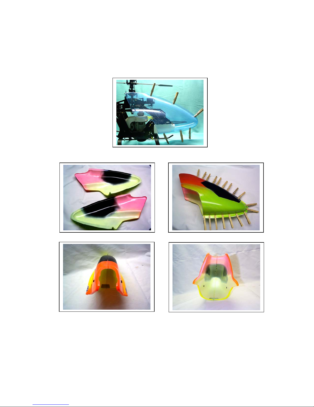
62. Canopy
Bag# Part# Qty Description
- 1921 1 Canopy - Lexan
1 1945 4 Canopy Grommet
1 1946 4 Thumb Screws
If canopy is to be painted on the inside, leave the blue plastic coating on the outside of the
canopy halves until finished painting. This will add protection should any overspray get on the
outside of the canopy.
Prepare canopy halves by washing in warm soapy water to remove grease and finger oils.
Dry completely.
When painting, use a good quality paint that will adhere to the lexan and be fuel proof. One
method is to use lacquer based R/C car body paints, such as Pactra lexan paint on the inside
of the canopy, followed by a fuel proofing coat of polyurethane for protection. A good
suggestion is Top Flite Luster Kote. It will not attack the lacquer color coats. A paint that
remains flexible is preferred, as the lexan can flex quite a bit.
Trim around the outside of the canopy halves with scissors. Lexan scissors for the R/C car
bodies works well. Where the 2 halves come together, leave about ½ inch. In the open areas,
leave about ¼ to 3/8 inch of lexan past the bends that are the edges of the canopy.
Glue the 2 halves together using a good glue that remains flexible, such as Pacer Zap A-
Dap-A Goo II or Shoe Goo. Use clothes pins to hold the halves together in place until
completely dry.
Remove the clothes pins and trim the glued edges to about ¼ inch.
Use some excess lexan to reinforce the areas at the bottom and top of the canopy where the
2 halves separate and open up in the back. This will add strength and resist vibration.
Drill (2) 9/32 inch holes, 2 3/16 inches from the top of the canopy and 1 1/2 inches from the
back edge of the canopy, on each side. These are the top canopy mounting holes. They are
only approximations. Trial fitting to clear all the controls and sideframes is necessary.
Put 2 grommets into the holes. Temporarily mount the canopy on the helicopter, putting the
top canopy standoffs into the grommet holes.
Hold the bottom of the canopy up so that it doesn’t hit the skid or the sideframe and prop it up
with a book.
Using a flashlight, shine the light into the canopy so that the shadows for the lower canopy
standoffs can be seen through the canopy. When satisfied as to the position of the canopy,
mark the position for the hole on each side of the canopy.
Drill (2) 1/16 inch holes in the marked locations. Mount the canopy on the helicopter and
check that the holes line up with the standoffs.
Open the holes to 9/32 inch and insert 2 grommets.
Mount the canopy and check for a final fit. Fasten the canopy using (4) thumb screws.
91
CANOPY

90
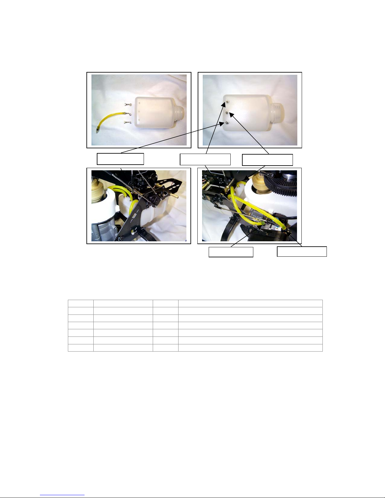
Cut a piece of fuel tubing about 4 3/8” long. Push one end onto the clunk. Push the other end
on the Double End Fitting, on the non-threaded end. This length is approximate, as the final
length may need adjusting slightly to get proper clunk operation.
Insert the Double End Fitting into the center hole in the tank, from the inside. Screw (1) Fuel
Tank Nut on the outside of the tank on the threaded nipple sticking out from the hole. Do not
tighten at this time. This is a trial fit only. This is the fuel pickup side of the tank.
Check for correct clunk operation by tipping the tank in various orientations to make sure the
clunk reached as far as it can, but does not get hung up on the end or sides of the tank.
Adjust the fuel line length as necessary.
Insert the tank into the opening in the lower sideframes from the front of the machine. The
end with the fittings go in first. The fittings should fit up in back of the rear of the radio tray.
Put the lid on the tank and tighten.
Connect a piece of fuel line tubing (medium size, not included) onto the center pickup line of
the tank. Connect the other end of the fuel line to the carburetor fuel inlet furthest away from
the little fuel bulb on the carb.
Connect a piece of fuel tubing (medium size, not included) onto the left-hand side fitting of the
tank. Connect the other end of the fuel line onto the other carburetor fitting (the one next to
the little fuel bulb on the carb. This is the return overflow for the fuel pump in the carb.
Connect a small piece of fuel tubing on the remaining fitting on the tank, and run it down
below the bottom of the lower sideframe. This the overflow vent for the tank.
When fueling the machine, disconnect the fuel line between the center tank fuel outlet and the
carburetor and fuel through the line into the tank. Fill until the fuel almost comes out the top of the
overflow vent of the tank.
89
FUEL TANK
61. Fuel Tank
Bag# Part# Qty Description
3 1880 1 Fuel Tank
3 1850 1 Clunk
3 1855 2 Single End Fitting
3 1860 1 Double End Fitting
3 1865 3 Fuel Tank Nuts
3 1870 1 Fuel Tubing
Drill (3) 3/16” holes about 1/2” from the closed end of the tank, all on the same face of the
tank, on the centerline with that face, about 1” apart with the center hole on the centerline of
that face.
Deburr each hole, both on the inside and the outside of the tank.
Insert (1) Single End Fitting in one of the end holes on the inside. A long, skinny hemostat
forceps works good for this. Screw (1) Fuel Tank Nut on the outside of the tank on the
threaded nipple sticking out from the hole. Be sure to get the nut tight to make a good seal.
Repeat with the second end hole.
Fuel Pum
p
Return
Fuel Inle
t
Fuel Tank Pickup
Fuel Return
Overflow Vent

88
FINS
60. Fins
Bag# Part# Qty Description
10A 1665 2 Sets Tailboom Clamps
MISC. 5010 2 M3x8 SHCS
MISC. 5050 4 M3x35 SHCS
MISC. 5105 4 M3 Locknuts
5 1832 1 Vertical Fin
5 1835 1 Horizontal Fin
Attach the horizontal fin to the fin clamp that was previously installed onto the tailboom. Use
(2) M3x8 SHCS. The horizontal fin should be perpendicular to the sideframes. Tighten the fin
clamp.
Mount the vertical stabilizer using (2 sets) of tailboom clamps, (4) M3x35 SHCS, and (4) M3
locknuts. Place one of the tailboom clamps just behind the tail gearbox mounting screw, and
one in front of the mounting screw.
Slip the (4) M3x35 SHCS through the 4 holes in the vertical fin and the 2 sets of tailboom
clamps. Attach (4) M3 locknuts to the ends of the screws. Do not tighten yet.
Make sure that the vertical fin is parallel to the sideframes and perpendicular to the horizontal
fin. Now tighten the screws and nuts.

87
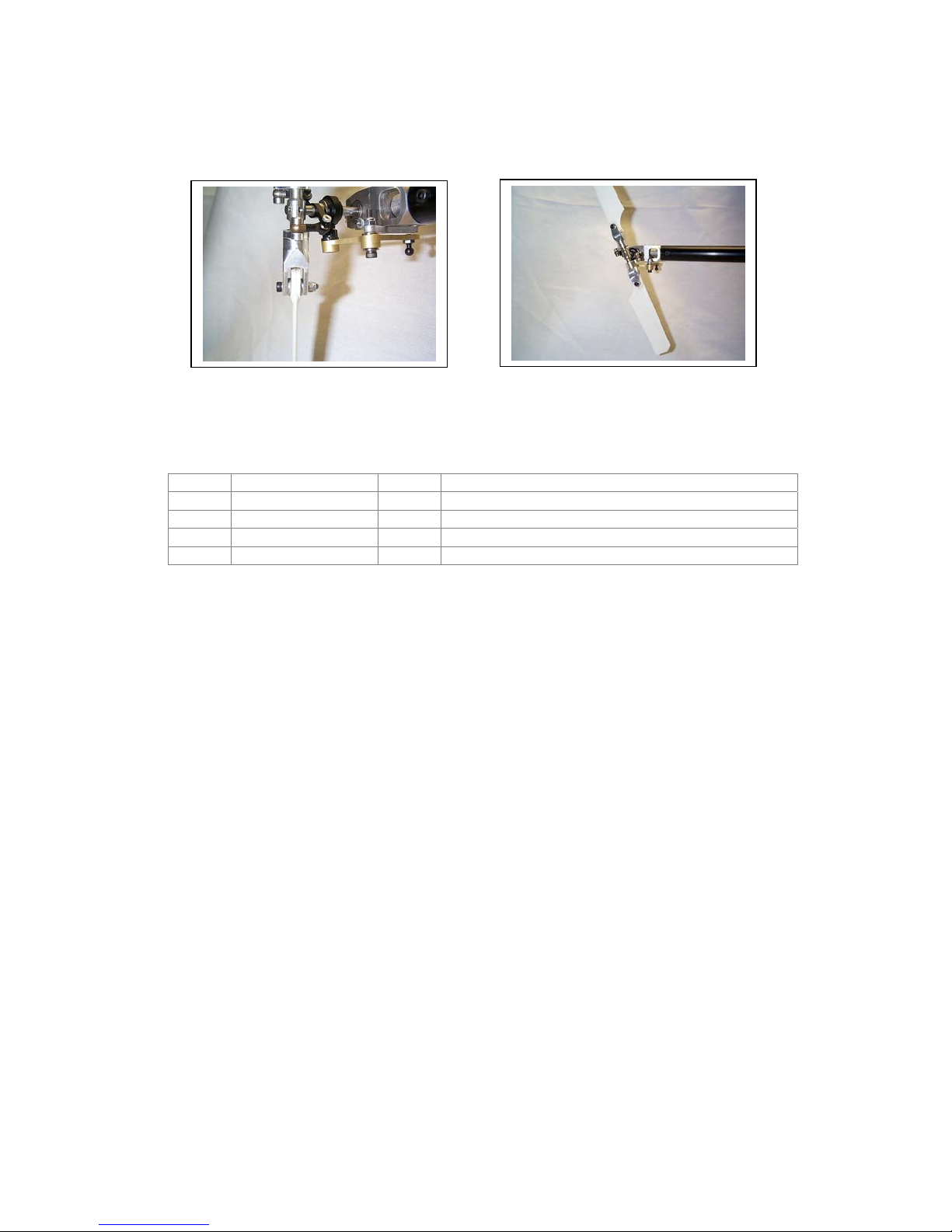
Adjust the tail rotor blades, so that when looking down on the blades, the top blade points
forward and to the right, indicating proper rudder offset for hover. Set the distance between
the two blades (when looking down at them) at about 20mm. This is the approximate amount
of rudder for hovering.
Make sure that the rudder servo arm is pointing straight down, perpendicular to the tailboom.
Hold the carbon fiber pushrod up in position next to the two pushrod ends. Measure and cut
the carbon pushrod so that it will fit all the way into the pushrod ends with everything
positioned previously.
Mix up some JB Weld Epoxy or use slow cure CA glue to permanently attach the pushrod
ends to the carbon fiber pushrod. Clean the pushrod end and the pushrod with alcohol, dry,
apply the glue and re-assemble to be sure alignment is maintained.
Let cure overnight.
There is a push-pull rudder servo upgrade that completes the push-pull
control system offered by Bergen R/C. It includes a dual ball bearing
supported arm that transfers the servo loads to the arm. Contact your
dealer or Bergen R/C Helicopters for more information.

86
RUDDER PUSHROD
59. Rudder Pushrod
Bag# Part# Qty Description
10B 251 1 Push Rod Carbon Fiber
10B 1983 2 Pushrod Ends
10B 1956 2 Ball Link 2.5
10B 5030 2 M3x16 SHCS
10B 5105 2 M3 Locknut
Push (1) M3x16 SHCS through the open end of (1) Pushrod End. Screw (1) M3 Locknut onto
the threaded end sticking out until tight.
Thread (1) ball link onto the threaded end about ¾ of the way on, to allow for adjustment in
both directions.
Repeat with the other pushrod end assembly.
Snap (1) pushrod assembly onto the tail pitch bellcrank.
Snap the other pushrod assembly onto the rudder servo arm ball.

85
TAILBOOM SUPPORT STRUTS
58. Tailboom Support Struts
Bag# Part# Qty Description
10B 1710 2 Tailboom Support Struts
10B 1715 4 Tailboom Support Strut Ends
MISC. 5015 2 M3x10 SHCS
MISC. 5050 1 M3x35 SHCS
MISC. 5105 3 M3 Locknuts
Temporarily insert the (4) support strut ends into the (2) tailboom support struts.
Mount one end of each of the support struts onto the bottom of the fin clamp using a M3x35
SHCS and a M3 locknut. Do not tighten at this time. One strut goes on each side of the fin
clamp.
Mount the other end of each tailboom support strut to the bottom of each lower sideframe
using (2) M3x10 SHCS and (2) M3 locknuts. The support strut end goes on the inside of the
sideframe and the locknut goes on the outside. Do not tighten at this time.
Align the top of the fin clamp perpendicular to the main frames. Check to make sure that all
support strut ends are inserted all the way into the tailboom support struts. This is a “dry fit” of
the struts. Verify alignment and tighten all screws.
Mix up some JB Weld Epoxy or use slow cure CA glue to permanently attach the support
strut ends to the tailboom support struts. Remove one strut at a time, clean the strut end and
the strut with alcohol, dry, apply the glue and re-assemble to be sure alignment is maintained.
Let cure overnight.
Re-assemble the tailboom support struts onto the machine.

84
Put the ball on the M2x5 PHSMS screw, followed by a M2 nut. Use threadlocker, but
sparingly.
Screw into the servo arm in one of the holes drilled so the ball will be facing up when installed
on the servo.
Put another M2 nut on the backside of the arm on the screw. Use threadlocker, sparingly.
There is a push-pull rudder upgrade available. It consists of a ball bearing push-pull
arm and all the hardware necessary to upgrade the machine to a full push-pull
control system. Contact your local Bergen R/C dealer for details.
83
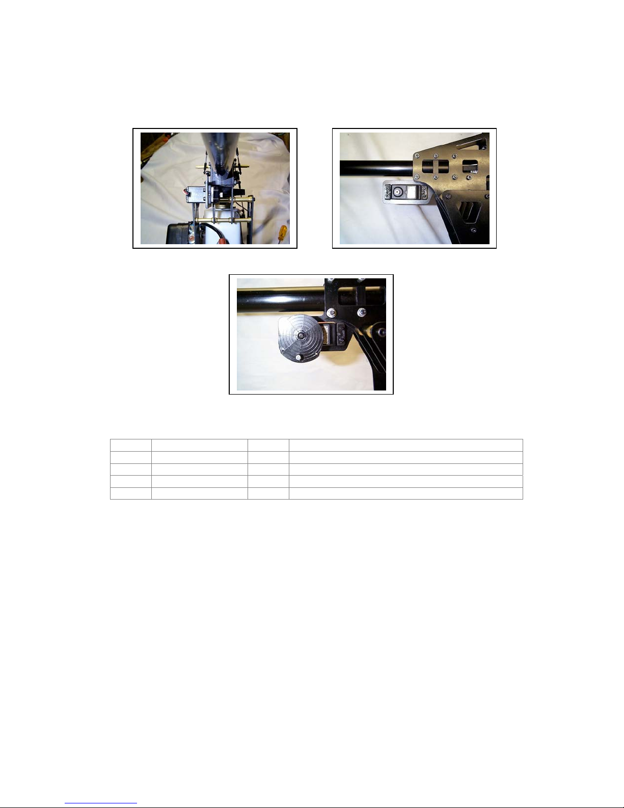
RUDDER SERVO
57. Rudder Servo
Bag# Part# Qty Description
11 1947 2 Plastic Servo Mount Tabs
11 5137 1 M2x5 Ball
11 5207 1 M2x10 PHSMS
11 5120 2 M2 Nut
Prepare the servo with the hardware provided with the radio system: install the rubber
grommets on the servo mounting ears, and then install the brass eyelets into the grommets
up from the bottom of the servo ear. Use self tapping screws provided by the radio system for
mounting the servos to the tray, or use M2.5x15 SHCS (not provided in kit). Use the plastic
servo mounting tabs as nuts. Screw the screws into the tabs, holding the tabs from the inside
of the mount as it is screwed in. Mount the servo in the rudder servo mount such that the
output shaft is toward the rear and facing to the right of the machine. The arm should be
pointing straight down when centered.
When tightening the screws, be sure to get the servo tight enough that it can’t move, but do
not squeeze the rubber grommet so much that the isolating properties of the grommet are
lost. The servo should be able to rock from side to side slightly when tightened. Paying
attention to this important note will increase the lifetime of the servos.
Prepare the Servo output arm by drilling as shown in the diagram. These are the correct
dimensions for a Futaba 9203 servo. Use a 2mm drill.
82
TAIL BLADES
56. Tail Blades
Bag# Part# Qty Description
10A 231B 4 Blade Grip Spacer
10A 5146 2 M3x19 w/11 Shoulder SHCS
10A 5105 2 M3 Locknut
MISC. 6015 2 Tail Rotor Blades
Mount (2) tail blades to blade grips using (4) blade grip spacers, 2 M3 X 19 shoulder SHCS
and (2) M3 nylon locknuts. 1 spacer goes on each side of the tail blade and in turn goes into
the blade grip.
While facing the side of the tailboom with the tail pitch mechanics, the tail rotor spins
counterclockwise. Make sure that the leading edges of the tail blades face in the
counterclockwise direction.
Tighten the tail blade bolts so that the friction just holds the blades in position when turning
the tail rotor. Do not overtighten.
81
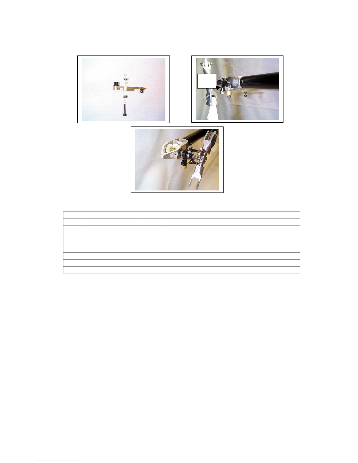
PITCH BELLCRANK
55. Pitch Bellcrank
Bag# Part# Qty Description
10A 240B 1 Bellcrank
10A 240A 1 Delrin Insert
10A 240C 1 Aluminum Spacer
10A 3086 2 3x7x3 Flanged Bearing
10A 5140 1 M3x16 w/6 Shoulder SHCS
10A 5155 2 M3 Brass Washer
10A 5190 1 Short Ball
10A 5105 1 M3 Locknut
Position the Bellcrank as shown in the first picture. Screw the short ball into the 2nd hole
facing down. Use threadlocker.
The delrin insert should be pre-assembled onto the bellcrank, but if not, then screw the insert
into the bellcrank from the top.
Press (2) 3x7x3 flanged bearings into the bellcrank, 1 from each side. The aluminum spacer
goes in the middle, between the bearings.
Put a brass washer on the M3x16 w/6 shoulder SHCS, then insert the screw into the bearing
from below.
Put another brass washer on the screw sticking up from the top of the upper bearing,
followed by the aluminum spacer.
Screw the assembly into the pitch arm bracket while fitting the medium ball from the pitch
slider into the delrin insert. Trim the delrin insert where it hits if it hits the base of the short
ball.
Tighten the screw while checking for binding on the bellcrank. It should be just snug without
binding or any up and down play. If it binds, add another brass washer in the middle, between
the bearings, to keep the bearings moving free.
Screw on the M3 Locknut from the top onto the protruding screw to act as a jamnut. Check
again for proper movement of the bellcrank.
Trim
Here

80
Attach each pivot plate arm eyelet and ball link onto each tail blade grip pivot arm using a
pivot plate shoulder bolt. The eyelet and ball link should go on the side of the arm facing the
center of the tail rotor main hub. Use threadlocker.
Slide the tail rotor main hub assembly onto the tail output shaft. Align the hole in the tail rotor
main hub with the indentation on the tail output shaft. Secure with a M3 X 4 setscrew. Use
threadlocker.
Remove both of the balls from the tail slider pitch plate and re-install one of them with
threadlocker.
Snap one of the ball links from the tail rotor blade grip onto the ball just re-installed on the tail
slider pitch plate.
Snap the second ball into the remaining ball link from the opposite tail rotor grip. Align the ball
hole with the hole on the tail slider pitch plate and secure with the M2 X 8 SHCS and the M2
nut. Use threadlocker.
Test the sliding action of the completed pitch assembly. It should move freely. You may have
to unscrew one of the ball links slightly to align it properly to the ball.

79
TAIL PITCH ASSEMBLY
54. Tail Pitch Assembly
Bag# Part# Qty Description
10A 1960 1 Tail Pitch Slider
10A 5137 2 M5x2 Ball
10A 5076 2 M2x8 SHCS
10A 5120 2 M2 Nut
10A 1961 2 Tail Special Ball Links
10A 1806 2 Pivot Plate Arm Eyelet
10A 1811 2 Pivot Plate Shoulder Bolt 4x4
10A 5195 1 Medium Ball
10A 5094 1 M3x4 Set Screw
Attach 1 medium ball to the pitch slider assembly. Use threadlocker.
Attach the (2) M2 X 5 balls to the aluminum pitch plate using (2) M2 X 8 SHCS and (2) M2
nuts. DO NOT USE THREADLOCKER YET. The balls are installed in the inside curves of the
pitch plate.
Slide the tail pitch slider assembly onto the tailrotor output shaft with the pitch plate facing
outward.
Screw the 2 tail special ball links to the (2) pivot plate arm eyelets.

78
TAIL ROTOR GRIPS
53. Tail Rotor Grips
Bag# Part# Qty Description
10A 231 2 Tail Rotor Blade Grip Assembly
10A 3052 2 5x10x4 Thrust Bearing
10A 5112 2 M10 OD Spacer
10A 5110 2 M3 Flat Washer
10A 5015 2 M3x10 SHCS
10A 1815 1 Tail Rotor Main Hub M5
The thrust bearing installs into the tail rotor blade grip assembly as follows: Note: Each of
these parts should be liberally greased with a high quality bearing grease before assembly.
Insert the 10mm OD spacer so it sits on the bearing in the grip.
Insert the thrust bearing race with the larger ID. Note: Use the tail rotor main hub to size the
thrust bearing races to find the larger ID. The groove for the balls should be facing out.
Insert the thrust bearing ball/cage assembly.
Insert the thrust bearing race with the smaller ID. The groove for the balls should be facing in.
Repeat the above numbered steps with the other tail rotor blade grip.
Slide the tail rotor blade grip assembly onto the tail rotor main hub. Attach each blade grip
using a M3 X 10 SHCS and a M3 flat washer. Use threadlocker.

77
WASHOUT ARM LINKS
52. Washout Arm Links
Bag# Part# Qty Description
11 1956 4 Ball link 2.5
11 1995 2 Collective Linkage 30mm
Thread (2) ball links onto the pitch linkage. Thread them on equally.
The final length of the link assembly will be 52mm from end – to – end, or 44mm from ball
center – to – ball center.
Make a second linkage assembly, and make sure that they are the same length. This is very
important, as incorrect linkage lengths will lead to binding.
Snap (1) linkage assembly onto the flybar control arm and onto one of the washout mixing
arms.
Repeat with the second link assembly on the other flybar control arm and the other washout
mixing arm. This second arm should have the ball positioned directly underneath the flybar
control arm.
View the head assembly. The two linkage assemblies just installed should be aligned
vertically with the main shaft. If not, correct whatever is wrong until alignment is achieved.
If the links are tight on the balls, use a ball link sizing tool to adjust the hole size in the links.
Washout Arm
Link

76
BELL PUSHRODS
51. Bell Pushrods
Bag# Part# Qty Description
11 1956 4 Ball link 2.5
11 2020 2 Pitch Linkage 75mm
Thread (2) ball links onto the pitch linkage. Thread them on equally.
The final length of the link assembly will be 102mm from end – to – end, or 94mm from ball
center – to – ball center.
Make a second linkage assembly, and make sure that they are the same length. This is very
important, as incorrect linkage lengths will lead to binding!
Snap (1) link assembly from the upper rotating portion of the swashplate (90 degrees to the
washout links) to the other end of the bell mixing arm. This is the longer end of the arm.
Repeat on the other side of the head.
If the links are tight on the balls, use a ball link sizing tool to adjust the hole size in the links.
Bell Pushrod
Other manuals for INTREPID GAS
1
Table of contents
Other Bergen Toy manuals


