Bergen Observer EB Instructions for use

WARNING!
The radio controlled model helicopter built from this kit is not a toy and is not meant for
children. It is a flying machine capable of causing property damage and serious bodily
harm to both the operator/assembler and/or spectator if not built and operated correctly
and responsibly. Rotating components, especially the main rotor blades, are an ever-
present danger.
Model helicopters operate differently than model cars and airplanes. Helicopters by their
nature are not positively stable, meaning that even if properly assembled and adjusted,
helicopters will not recover from an unwanted flight attitude, nor will they hold any
particular orientation without constant control inputs from the pilot.
IT IS YOUR EXCLUSIVE RESPONSIBILITY TO PROPERLY BUILD, MAINTAIN
AND OPERATE THIS HELICOPTER. Bergen R/C Helicopters has spent
considerable time making this product reliable and easy to build, but only
the operator can insure that it is safe. Because the safe operation of this
helicopter is beyond the control of the Manufacturer and distributor, the
owner/operator assumes all risk of use.

Construction Manual
Acknowledgments
Bergen R/C Helicopters wishes to thank our friends and customers for their
continuing support during the development of the Intrepid Helicopter.
The Instruction Manual and illustrations were completed with the input of
numerous customers and staff. We wish to recognize Gary Wright, who had
been the test pilot and helicopter guru in its early years. We would also like
to recognize Mike DeMetz for his continuous support and knowledge in
electronics and maintenance.
Staff
Chris Bergen; Chief Executive Officer
Larry Bergen; Chief Design Engineer and General Manager
Maryann Pratt; Office Management
Mike Bergen; Programmer, Engineer
Larry Mihills; Machinist
Malorie Zastrow; Test Pilot/Engineer
Bergen R/C Helicopters LLC
1101 Follett Drive
Cassopolis, MI 49031
Voice: (269) 445-2060
Fax: (269) 445-2250
Web: www.bergenrc.com

Introduction
The first of its kind, interchangeable modular engineered helicopter to accommodate
the beginner to a FAI expert…
An idea in 1994 to manufacture an interchangeable, modular helicopter, led to the
research and development in 1995. Focusing on quality, engineering details, and
price, a prototype was produced. After extensive test flights and fine-tuning, the
INTREPID HELICOPTER is now what you see today. The first of its kind, strength
combined with simplicity for easy maintenance and flying.
Although beginners can successfully build and fly their INTREPID, the process can be
made significantly easier with the help of an experienced modeler and instructor pilot.
We recommend that all beginners join the Academy of Model Aeronautics (AMA). The
AMA is a non-profit organization that provides services for modelers. The AMA can
help you locate a model aircraft club in your area with an instructor pilot (you can also
check with your local hobby shop). Membership benefits include a monthly magazine
and liability insurance. Many flying clubs require an AMA modeler’s license to operate
a model on their flying field. For more information on the AMA contact:
Academy of Model Aeronautics
5151 East Memorial Drive
Muncie, IN 47302
Phone: (317) 287-1256

Consumer Warranty
IMPORTANT! Before building the Observer EB Helicopter kit, read and fully understand the
following warranty, and review the entire Construction Manual. By building and/or flying this
helicopter you indicate your acceptance of the following warranty terms and conditions, and further
agree to build and operate this helicopter in safe and responsible manner.
If you find any term or condition unacceptable, or if you feel that this helicopter is just not suited to
you, you may return it to your place of purchase in NEW and UNUSED condition within thirty (30)
days of the date of purchase for a refund of the purchase price less shipping and handling. Partially
assembled kits, and kits with opened parts packs or missing parts can not be returned for a refund.
Warranty: 1. Bergen warrants to the first consumer Purchaser that the Observer EB helicopter
substantially conforms to its published description when used as intended as a
hobby product, and will be free from defects in materials and workmanship for a
period of 90 days after the date of purchase. Bergen R/C will repair or replace (at
his option) any defective part, and supply any missing part at no charge to the
Purchaser within this period. We make no warranty, express or implied. This
warranty does not apply to parts damaged by improper assembly, modification,
abnormal service or handling, or crashes.
2. To take advantage of this warranty, the Purchaser must provide proof of purchase,
and ship any defective part (at Purchaser’s cost) to Bergen R/C for repair or
replacement.
3. It is the responsibility of the Purchaser to properly assemble, maintain and operate
this helicopter in accordance with manufacture’s instructions, AMA safety codes,
local laws and ordinances, and COMMON SENSE. It is also the responsibility of the
Purchaser, when operating this helicopter, never to operate it in any way, which
might endanger persons or property including the Purchaser. Purchaser is advised
to carry appropriate liability insurance such as that commonly provided to modelers
by the AMA.
4. THIS WARRANTY SPECIFICALLY EXCLUDES THE IMPLIED WARRANTIES
OF MERCHANTABILITY AND FITNESS FOR A PARTICULAR PURPOSE. The
selection of this helicopter for a particular application or use (beyond
hobby/entertainment) is the sole responsibility of the Purchaser. Any advice supplied
by any representative of Bergen R/C pertaining to any particular application is given
freely as an opinion and is not meant to bind Bergen R/C or in any other way modify
this warranty.

1. Not withstanding the paragraph above, this warranty is in addition to whatever
implied warranties may be granted to the Purchaser by law. To the extent
permitted by law, all implied warranties, including the warranties of merchantability
and fitness for a particular purpose are limited to a period of (1) year from the date
of purchase. Some states do not allow limitations on how long an implied warranty
last, so the above limitation may not apply.
2. This warranty shall be the sole and exclusive remedy available to the Purchaser.
Correction of defects, in the manner and for the period of time specified above, shall
constitute complete fulfillment of all liabilities and responsibilities of Bergen R/C to
the Purchaser, and shall constitute full satisfaction of all claims, whether based on
contract, negligence, strict liability or otherwise. Bergen R/C shall not be liable for
any cost or expenses incurred in; the replacement of any effective or non-
conforming parts, and IN NO EVENT SHALL BERGEN R/C BE LIABLE FOR
INCIDENTAL OR CONSEQUENTIAL DAMAGES, OR ANY DAMAGES DUE TO
THE USE OR INABILITY TO USE THIS PRODUCT. Bergen R/C shall not be
liable, or in any way responsible, for any damages related to modifications, repairs,
attempted repairs, or crashes. IN NO EVENT SHALL BERGEN R/C’s
OBLIGATIONS TO THE PURCHASER EXCEED THE ORIGINAL PURCHASE
PRICE PAID BY THE PURCHASER.
3. Some states do not allow exclusion of incidental or consequential damages, so the
above exclusion may not apply. This warranty gives the Purchaser specific legal
rights. The Purchaser may also have other rights, which vary, from state to state.
4. No modification or amendment to this warranty will be effective unless reduced to
writing and signed by an authorized representative of Bergen R/C Management.
If you do not understand any aspect of this warranty, you may contact
Bergen R/C Helicopters for clarification. IF YOU DO NOT AGREE WITH ANY ASPECT OF THIS
WARRANTY, RETURN THE UNASSEMBLED HELICOPTER TO YOUR MANUFACTURER FOR A
REFUND.
Bergen R/C Helicopters believes that information contained within its published materials is accurate
as of the date of publication, and is not responsible for inadvertent errors or omissions. Bergen R/C
reserves the right to make changes and improvements in its products without notice.
Chris and Larry Bergen
Bergen R/C Helicopters

Congratulations on your purchase of a Bergen R/C Helicopters Observer EB.
The EB stands for Extended Boom, allowing the use of 810 mm rotor blades.
There are a few things we recommend in the assembly and use of your Observer EB, and we’ll spell those
out as we go, but for now, our first recommendation is a good quality set of hardened allen drivers. We
have found that standard allen wrenches are too soft, and you run the risk of rounding off the inside hex
of the SHCS that we use in the assembly of the helicopter.
You will also need Blue Loctite throughout the assembly, and some good quality grease that is compatible
with rubber, which will be used to lube the O’rings in the rotor head.
Oil and fuel mix is a hot topic on the internet, and you will use what you want, but here, at least, is our
recommendation based on our experience of many years of using gas engines in helicopters. We
recommend using 100% synthetic oil such as Blue Marble, available from B.H. Hanson, Yamalube, or
even Pennzoil outboard marine engine oil. The clue here is 100% synthetic, not a blend, not ashless, and
certainly not a concentrated oil such as Amsoil, that requires using less oil.
Mix your oil, 6 oz to a gallon, of 87 octane gasoline, not camper fuel or some other substitute. Higher
Octane fuel will NOT add performance, just cost, and may cause predetonation. This mix to be used for
the first 2 gallons of use, then reduce the oil to 5 oz per gallon.
Our reasoning for this mix is simple. We feel that more oil is a safety measure for your engine. It’s
protection against a lean run that may be accidental due to an air leak or by not being used to tuning a
gas engine. Many engines have had to be replaced due to the fact of burning them up because of a lean
run, using less than the recommended amount of oil. As I said earlier, you will run what you want, but if
you want the performance out of your helicopter that you purchased it for, use our recommendations and
it will work just fine.

Start with the landing gear. Assemble the skids and cross bars as shown, leaving them loose for now.
Locate the landing gear skid bars in bag #1, use them to locate and drill 2 holes in each cross bar. Center
the skid bar fore and aft, as well as side to side, and use a #30 or 1/8th drill bit to drill through the cross
bar. Set the landing gear aside for now.
Gather all of the engine components. Note the tapered end of the crankshaft. Also notice the sharp edge
at the end of the taper.
You’ll want to remove that sharp edge, either by buffing or carefully grinding the edge. Install the pull
start adapter using 3 ea 5X12 FHCS. Loctite is NOT necessary here, as the countersunk G10 will hold
them quite nicely.

Install the pull start using 4 ea 4X12 SHCS. Again, loctite isn’t needed, however if you feel the need, you
can use a drop of CA glue in place of loctite. Note the orientation of the pull start handle, on the same
side as the carburetor insulator block. On the opposite end of the engine, install the fan shroud mount
plate, using 4 ea 5X12 SHCS and loctite this time. Also note the orientation of the plate; this will be
important when you mount the fan shroud.
Installing and dial indicating the fan will be more accurate with the spark plug removed. Seat the fan on
the tapered end of the crank, and install the 6X25 SHCS and ¼” split washer, using loctite. Do not
torque the bolt down yet, just snug it.
Dial indicate the fan, looking for runout indication as shown.
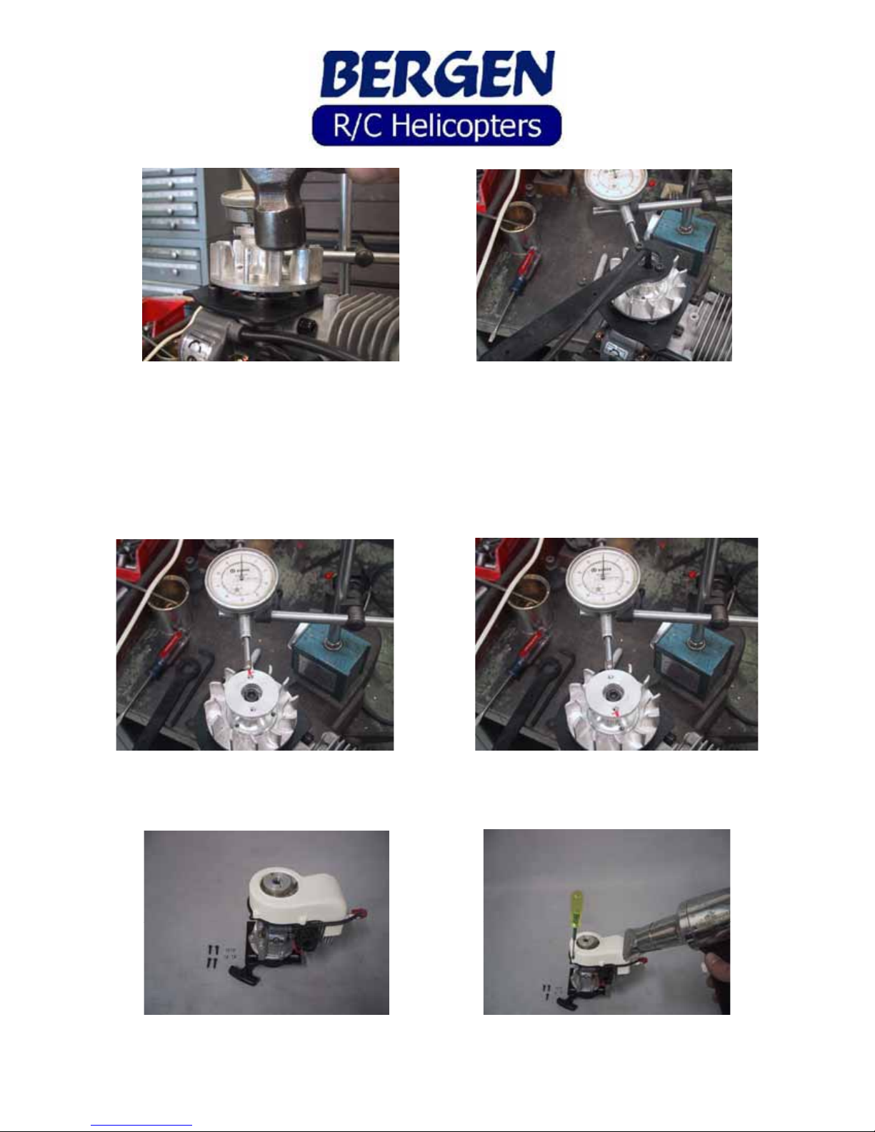
Tap the high side down carefully, using a small hammer, hitting flat on the tops of the fan blades, then
checking the runout. It usually takes only a sharp tap to bring it in. Now torque down on the bolt
holding the fan to the engine. Check the runout again. If it has runout, give it another tap on the high
side and recheck. You should be able to get the runout to less than .002 without a lot of difficulty. If you
are having difficulty, remove the fan. Check the runout of the crankshaft itself. It should also be less
than .002. Look into the fan hub to ensure there is no burr in the tapered end, preventing it from seating
properly.
This is what it should look like when you’re done. One side reads 0.00, as does the opposite side. This
took all of 10 minutes, including taking the pics!!
Set the fan shroud over the fan and head of the engine. Carefully, using a hair dryer, warm the shroud to
fit it to the mount, installing the 3X16 SHCS as you go.

When you get all 4 SHCS installed, warm the entire shroud to relieve any stress that could cause cracks
in the future. Install 4 ea 3M locknuts on the SHCS. DO NOT over torque these nuts; you will crack the
ears on the first run of the engine. Snug is good enough.
Gather the lower frame components from bag #1. Start with the “butterfly” and the 2 “Front Frame
Plate Bars”, noting the orientation.
Using 6 ea 3X16 SHCS and 3M locknuts, mount the bars on the butterfly, then slide the one leg into the
lower frame, again using 3X16 SHCS and 3M locknuts through the “front frame plate bar” to secure in
place. Repeat for other lower frame half. Note that the lower frames are “handed”, left and right. You
can tell the difference by the countersunk holes on the lower edge of the frame. The countersink faces
“out”.

Install the rear bulkhead using 4 ea 3X16 SHCS and 3M locknuts, then install the landing gear skid bars,
front and rear, using 4 ea 3X8 FHCS.
Assemble the rear battery tray with battery tray spacers, using 6 ea 3X8 FHCS and loctite.
Install the battery tray into the frames using 4 ea 3X8 SHCS and loctite. Note the tray spacers are on
top. Install the “Front Frame Block and Arm Mount” on the rear of the butterfly, using 4 ea 3X16 SHCS
and 3M locknuts.

Install the lower frame assembly onto the landing gear, using 4 ea 3X16 SHCS and 3M locknuts. Center
and rotate the skid tubes to your liking, then drill a #50 pilot hole in the boss, into the aluminum skid
tube, on the underside of the gear and install the 2 ea 3X8 self tapping screws. I typically install these
into the rear cross bar, leaving the front crossbar able to flex.
Install the engine into the lower frames, spark plug facing to the rear (remove the plug for ease of
installation). Note the vertical slots in the lower frames and the horizontal slots in the pull start adapter.
In these slots, install 4 ea 3X18 SHCS with the thick special washers provided, one washer on the outside,
one on the inside.
Turn the framework over to access the underside, and install the washers and 3M locknuts. Do not
tighten at this time, as you will need to set the gear mesh later on. Note that you can move the engine up
and down, as well as forward and aft.

Locate the delrin bushings, steel inserts and 4X16 SHCS. Note the chamfer on the steel insert. Install
with the chamfer toward the head of the bolt. Install the delrin bushings onto the fan hub using loctite,
and tighten securely.
Assemble the clutch components, clutch, clutch bell, triple bearing block, and retaining collar w/3X3
setscrews. Use loctite on the setscrews in the retaining collar.
Install the clutch system onto the delrin bushings on the fan hub. Gather up the upper frames, 4 ea
flanged bearings, and collective axles.

Press the flanged bearings into the upper frames, making certain to seat the flange down. Be sure to
make a right and a left, with the flange on the inside of the frames. Put a drop of CA glue around the
outer edge of the bearings to secure them in place, being careful not to get any glue in the bearing itself.
Insert the axles into one side frame and slide the opposite side frame onto the axles.
Slide the upper framework onto the bulkheads, and install 4 ea 3X35 SHCS through the holes in the
frames and bulkheads. Secure with 4 ea 3M locknuts. Install 4 ea 3X8 SHCS and 3M washers into the
triple bearing block above the clutch, loosely for now. Find the Elevator Yoke assembly and the 2 shafts
with flats on them. You’ll need 2 ea 3X4 SHCS and 3M washers as well.
Note the two shafts are different; one has flats on only one side. Install both shafts into the elevator yoke
with the flats fitting into the broached holes. Use loctite on the 2 ea 3X4 SHCS and 3M washers.
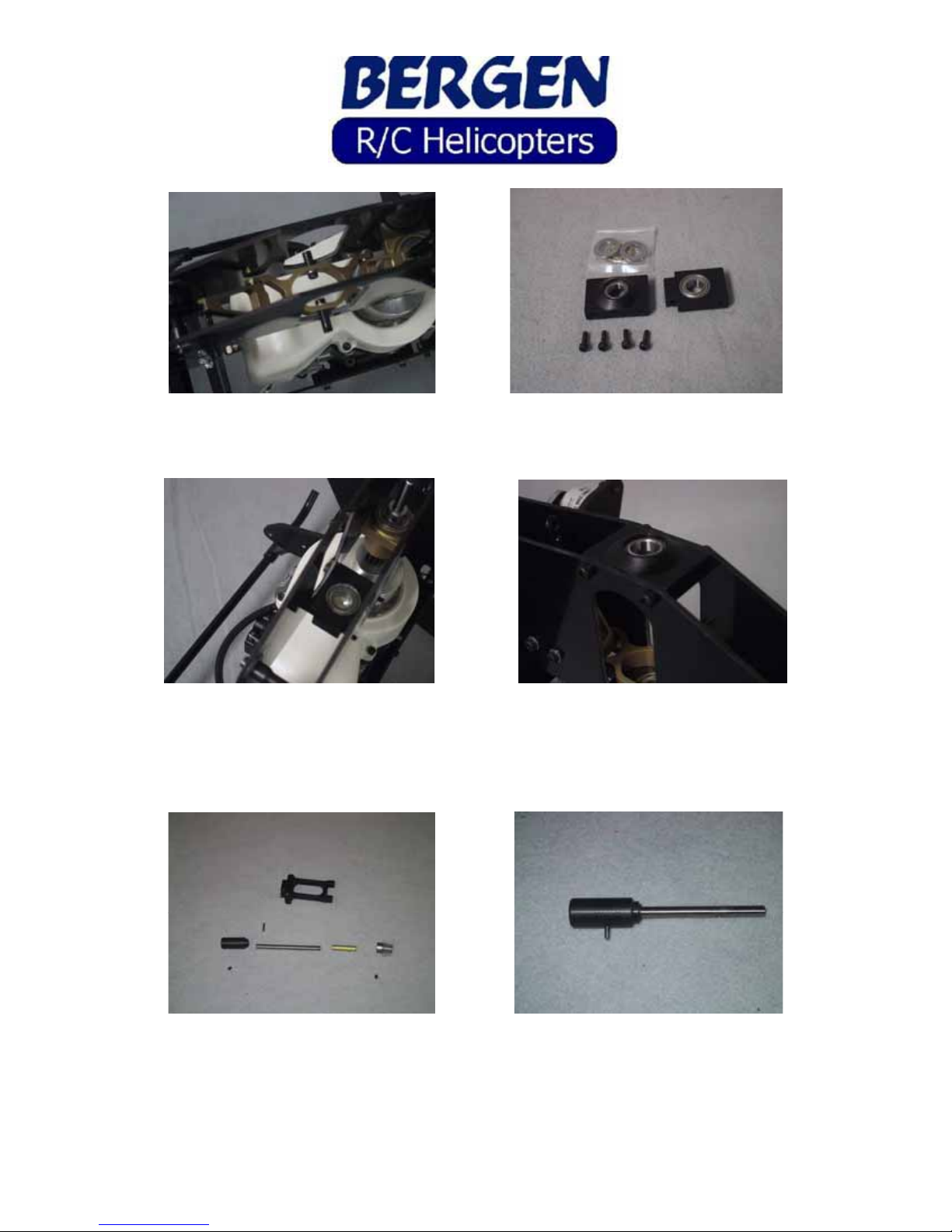
Insert the elevator yoke into the upper frames, with the longer of shaft on the right side of the helicopter.
Find the 2 main shaft bearing blocks. Note the cutout portion on the lower bearing block.
Install the lower main shaft bearing block, using 2 ea 3X35 SHCS, note the orientation of the bearing,
facing up. The elevator yoke is removed for clarity. Install the upper main shaft bearing block, using 4
ea 3X8 SHCS also note the orientation of the bearing, facing down this time, hump side up. Loosely
install 2 ea 3M locknuts on the lower bolts.
Assemble the tail drive transmission next. Insert the shaft into the delrin coupler until the holes line up
and install the cross pin securing the two pieces together.
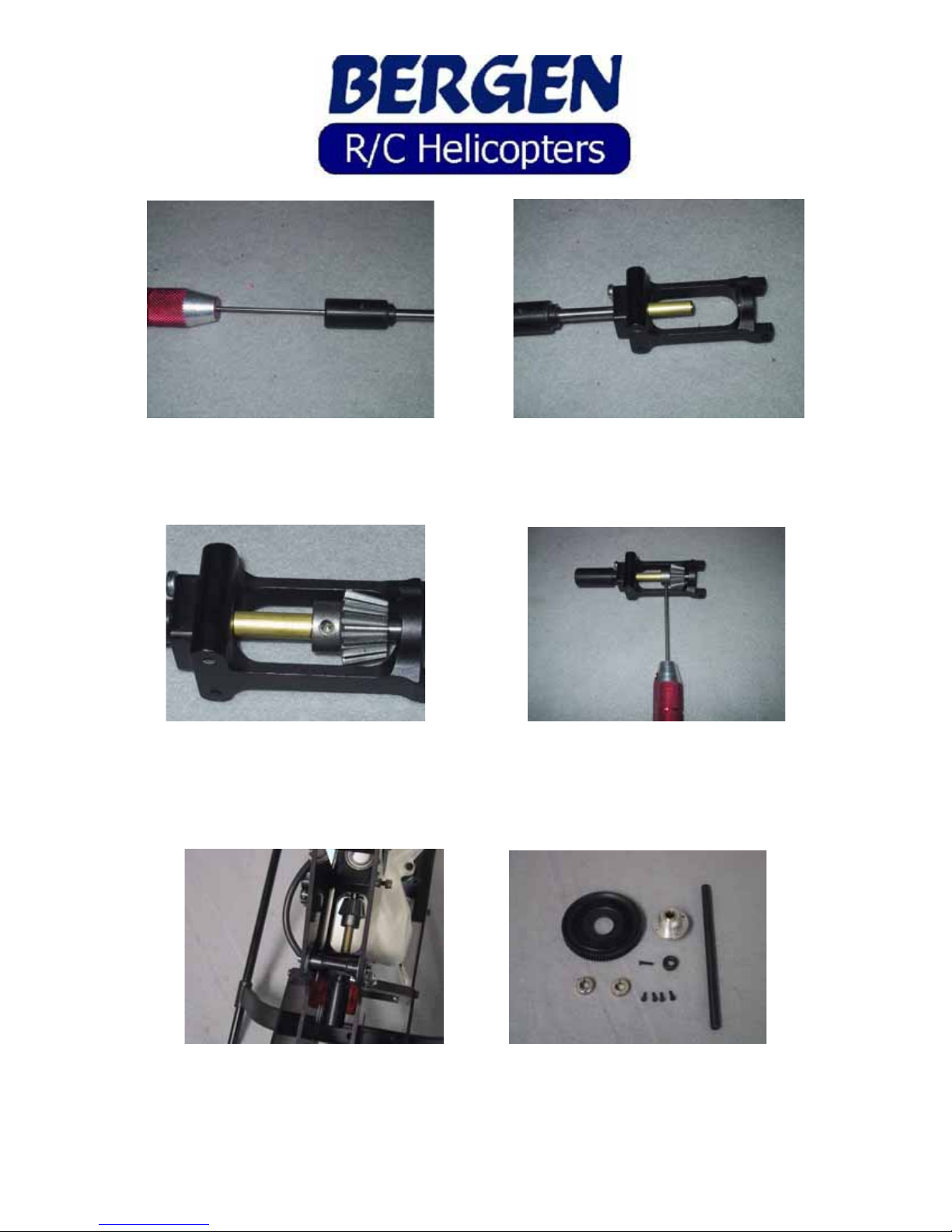
Secure the cross pin with a 3X4 setscrew threaded into the rear of the shaft, using loctite. Make doubly
sure the setscrew secures the crosspin. Insert the shaft into the rear of the transmission cradle through
the bearing, and slide the brass tube onto the shaft.
Install the tail pinion onto the shaft and slide the shaft all the way in, through the forward bearing.
Looking through the setscrew hole, locate the divot in the shaft. If it doesn’t line up, look through the
second hole in the pinion. Install a 3X4 setscrew in this hole, using loctite. A second setscrew is not
necessary and may interfere with the bolts in the main gear.
Install the tail transmission into the upper frames, engaging the ears into the lower bearing block. In
these “ears”, note the slotted hole for adjustment up and down to set the mesh. You’ll need to remove the
3X35 SHCS previously installed, the reinstall it after getting the transmission in place. Don’t tighten it
just yet. Loosely install 4 ea 3X8 SHCS into the rear 4 holes of the cradle through the frames. Locate the
main gear components next.

Install the autorotation hub into the main gear with the longer portion of the hub facing up. Use 4 ea
3X8 Low Head Cap Screws and loctite to secure. Insert the main shaft down through the upper bearing
block, install the 3 pieces of the thrust bearing and 1 split collar on the shaft with the “ring” facing up
toward the bearing, slide the shaft down a little farther and install the second split collar, below the
elevator yoke, with the “ring” facing down toward the bottom bearing.
Continue pushing the main shaft down, through the bottom bearing, insert the main gear below the
bottom bearing block and slide the main shaft through the auto hub. Place the bottom collar on the main
shaft and install the 4-40 bolt through the collar and mainshaft, with loctite. This is one of the 2
standard, not metric, bolts on this helicopter.
Pull up on the mainshaft, push down and tighten the lower split collar. This is where the hardened allen
drivers are a must. You’ll notice the heads of the bolt are turned down to fit the collar, making them
very easy to strip the heads. Slide the upper collar and thrust bearing up to the upper bearing and secure
the bolt. DO NOT use loctite on these bolts.
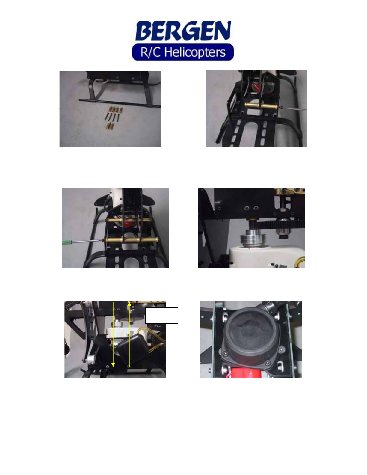
Gather the 26 mm threaded frame spacers and 29 mm non-threaded frames spacers with 4 ea 3X40
SHCS. Secure the rear of the frame sets together by inserting the bolt through the frames and spacer,
into the threaded spacer in the middle.
Install remaining bolts and frame spacers. Now go back, and one at a time, remove a bolt, loctite and
reinstall. Loosely install 4 ea 3X8 SHCS and 3M washers into the triple bearing block.
Now set the gear mesh between the drive pinion and main gear by moving the engine fore and aft, moving
the triple bearing block fore and aft as well, maintaining vertical alignment through the start shaft. In
other words, you DO NOT want the drive train cocked to get proper engagement of the gears. Proper
engagement means the gears spin freely with minimal or no backlash. The main gear is machined, and as
such, has no high spot. Carefully tighten the bolts in the triple bearing block, and carefully tighten the
bolts and nuts in the pull start adapter plate. Check the mesh, if it moved, try again. Remember the fore
and aft adjustment in the plate and the vertical adjustment in the frames. The fan hub should be pushed
right up against the clutch when adjustment is complete. Loctite the bolts in the triple bearing block.
Parallel to
each other
Set the tail gear pinion mesh by loosening the thru bolt holding the lower main shaft bearing block and
transmission cage in place, and loosening the 4 bolts at the rear of the transmission cage. Tap down on
the front of the cage at the point shown until you get a smooth running mesh with little or no backlash.
The “step” of the ears on the transmission will sit flush with the top of the bearing block. Now tighten
the thru bolt, loctite and tighten the 4 bolts in the rear of the transmission cage.
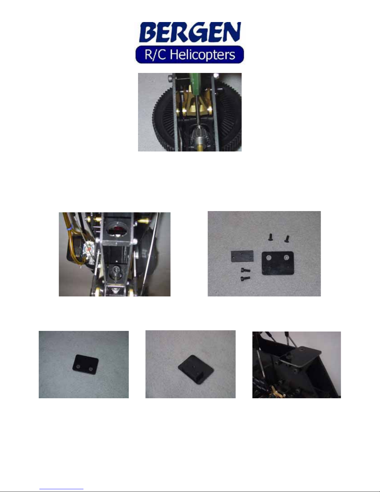
Install 3 sets of the boom clamps into the rear of the upper frames, using 6 ea 3X35 SHCS and 6 ea 3M
locknuts, but do not tighten them yet. Locate the gyro mount plate and three hole block.
Assemble the plate using 2 ea 3X8 FHCS in the c-sunk holes, then install into the frames above the boom
clamps using 2 ea 3X8 SHCS.

The swashplate is next; install 4 ea medium balls on the inner ring, using loctite. After installing these
balls, make sure the eyeball in the center of the swashplate moves freely. If not, check that the threads of
the balls haven’t gone in too deep, pushing on the eyeball. Remove some of the threaded end, if
necessary. 4 ea short balls go in the outer ring, with loctite.
Slide the swashplate onto the main shaft and snap the links from the elevator yoke onto 2 of the outer
balls. Gather the components of the washout unit next.
Assemble 2 ea washout arms by installing a “porkchop” radius link onto the arm, and installing a 10m
crosspin, securing the crosspin with a 3X4 setscrew and loctite. Note the orientation of the arm and
“porkchop”. You’ll also note there are 2 packages of “porkchops”, marked left and right. The difference
is the direction that they snap onto a ball. We suggest for now that you use the “left” handed porkchops.
Other Bergen Toy manuals


Popular Toy manuals by other brands

Hobbico
Hobbico AquaCraft V24 One-Design Assembly and operation manual

Girl tech
Girl tech Password Phone G8067 instruction manual

Eduard
Eduard 48 612 manual

LEGO
LEGO 3942 Friends Assembly guide

Faller
Faller ST. MARTIN'S GATE IN FREIBURG BREISGAU... Assembly instructions

Twister
Twister Storm 3DX Assembly & flight training guide


FMS
FMS T-45 instruction manual

Urban Air
Urban Air UFM - 13 LAMBADA Operations and flight manual

Enabling Devices
Enabling Devices 4122 user guide

SPECIAL HOBBY
SPECIAL HOBBY Supermarine Seafire FR 47 instructions

Our Generation
Our Generation RV Country Cruising BD35163Z manual

Century Helicopter Products
Century Helicopter Products Predator Casser manual