bern NFPA-13 Owner's manual

Waterflow Alarm Switch
Installation and Operation Instruction
1supply@bernofire.com
www.bernofire.com
Waterflow Alarm Switch(WAS)
1- Product Overview
The Waterflow alarm switch usually installed in the main pipe or branch
pipe of the pipe system. This Switch is an important part of the automatic
sprinkler system. When the Paddle detects the water flow, the water flow
signal will be converted to electrical signal, and then switch on the alarm
system, at the same time, the fire zone will be indicated.
UL Listed, Vane-type Waterflow Alarm Switch mount to water-filled pipes
in fire suppression systems.
Waterflow Alarm Switch in the pipe deflects a vane, which produces a
switched output usually after a specified delay. Most of the Waterflow
Alarm switches have a pneumatically controlled mechanical delay
mechanism.
Waterflow Alarm Switch usually installed in the main pipe or branch pipe
of the sprinkler pipe system. When the vane detects the water flow, the
water flow signal will be converted to electrical signal, and then switch on
the alarm system or start the fire pump directly, at the same time, the fire
zone will be indicated.
Standard Specifications
Static Pressure Rating 450 PSI Operating Temperature
Range
32°F to 120°F (0°C to 49°C)
Maximum Surge 18 Feet Per Second (FPS) Enclosure Rating indoor use
Triggering Threshold
Bandwidth (Flow Rate)
4–10 GPM
Cover Tamper Switch
Standard with UL models
Conduit Entrances
Two openings for ½˝ conduit. One
open, one knock-out type
Compatible Pipe
Steel water pipe, schedule 10
through 40
Contact Ratings
Two sets of SPDT
(Form C) 10.0 A, ½ HP @ 125/250 VAC 2.5 A @ 6/12/24 VDC
NFPA-13
NFPA-13D
NFPA-13R
Service Use:
Automatic Sprinkler
One or two family dwelling
Residential occupancy up to four stories
National Fire Alarm Code NFPA-72
CAUTION
Do not trim the paddle. Failure to follow these instructions may prevent the device from operating and will void the warranty. Do not
obstruct or otherwise prevent the trip stem of the Waterflow alarm switch from moving when water flows as this could damage the
Waterflow alarm switch and prevent an alarm. If an alarm is not desired, a qualified technician should disable the alarm system.
WARNING
- Please read the instructions carefully before installation, any damage caused by improper installation will not be liable for the
manufacturer.
- Before installation, check the nominal diameter, nominal pressure, temperature range and fluid of the Waterflow Alarm Switch, do not
install if the technical parameter of Waterflow Alarm Switch don't match the requirement of the pipe system.
- The Waterflow Alarm Switch can be mounted on horizontal or vertical pipe. On horizontal pipe it should be on the top of the pipe or the
side of the pipe, do not at the bottom of the pipe. On vertical pipe it should be mounted on the pipe which the water flow is upward.
- The pipe length before and after the Waterflow Alarm Switch must be no less than 5 times the pipe diameter, and choose the correct
Waterflow Alarm Switch according to the pipe nominal diameter technical parameter table.
- Waterflow Alarm Switch direction must be same as the arrow direction, must not be installed in opposite direction.
- Leave enough space for easy installation and maintenance.
WARNING
Installation must be performed by qualified personnel and in accordance
with all national and local codes and ordinances.
Shock hazard. Disconnect power source before servicing. Serious injury
or death could result.
Risk of explosion. Not for use in hazardous locations. Serious injury or
death could result.
Waterflow Alarm Switch
Installation and Operation Instruction
2supply@bernofire.com
www.bernofire.com
CAUTION
Hole must be drilled perpendicular to the pipe and vertically centered. Refer to the
Compatible Pipe/Installation Requirements chart for size.
Correct Incorrect
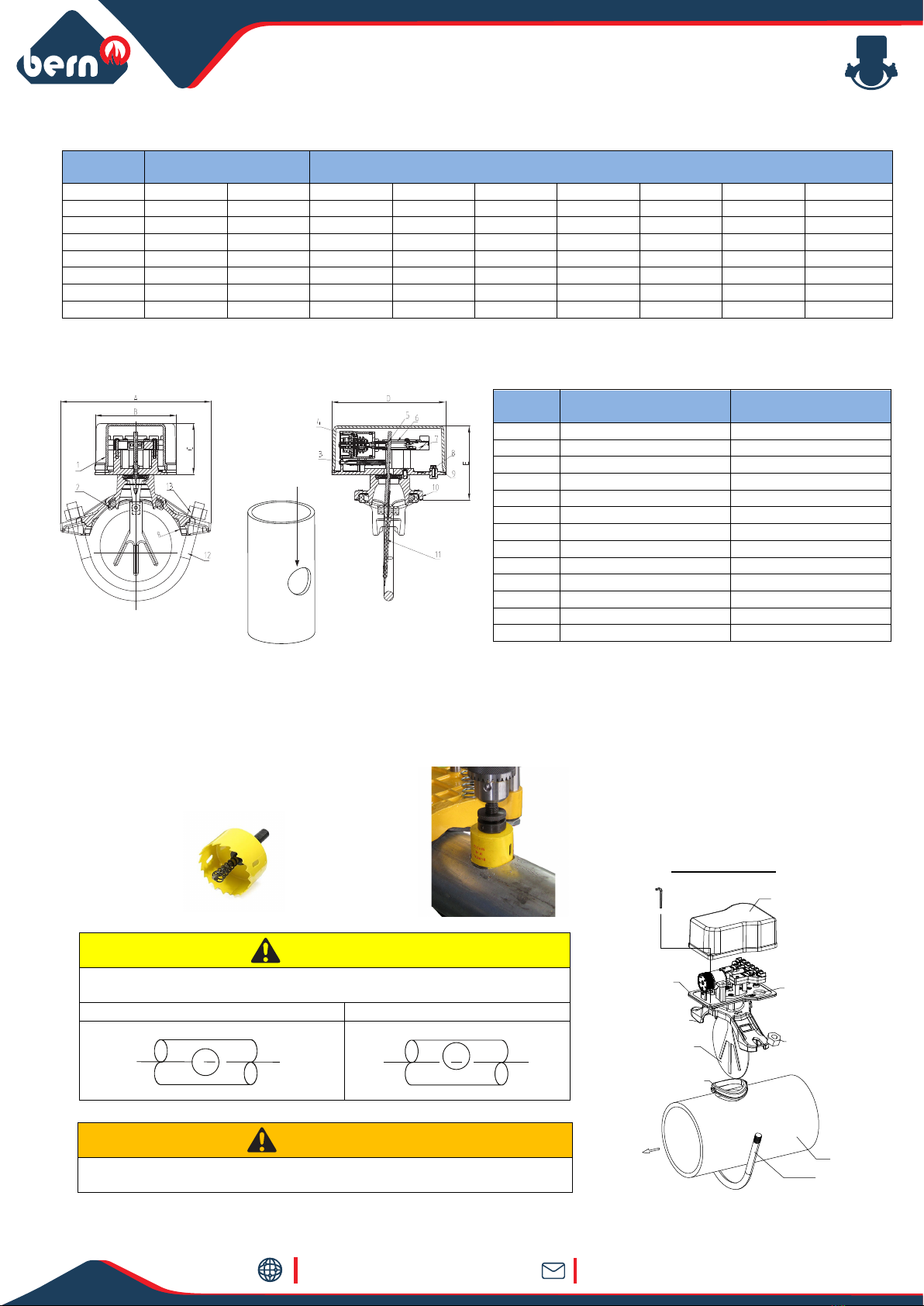
Nominal
Dimension Size Dimension
DN Inch mm R A B C D E Hole Dia
50 2” 60.3 30.15 116 100 59.5 140 79.5 32
65 2 ½” 73 36.6 120 100 59.5 140 79.5 32
80 3 88.9 44.45 145 100 59.5 140 80.9 51
100 4 114.3 57.15 185 100 59.5 140 98.5 51
125 5 139.7 69.8 212 100 59.5 140 82.6 51
150 6 165.1 82.55 254 100 59.5 140 90.4 51
200 8 219.1 109.55 298 100 59.5 140 90.5 51
2-
No. Part Material
1 Cover ASTM B85-96 383.0E
2 Rubber Gasket EPDM
3 Spring SS304
4 Air Delay Device PC GV3410R
5 Stem Sealing Gasket SS304+NBR
6 Connecting Rod POM 500P
7 Micro-Switch PC GV3410R
8 Connection Plate ASTM B85-96 383.0E
9 Connection Plate Seal NBR
10 Saddle ASTM A536,65-45-12
11 Vane PTFE
12 U-Bolts Carbon Steel Zinc Plated
13 Nuts Carbon Steel Zinc Plated
Hole Dia
WARNING
Remove all the materials in the pipe, otherwise, the pipe can be blocked.
Parts Description
Electrical Conduit
Entrance
U-Bolt Nut
Saddle Gasket
Roll Paddle
Pipe Paddle
Mounting Plate
Pipe
U-bolt
Water Flow
Cover
Tamper proof wrench
Part
Material Specifications
3-
a) Hole Cutting
Hole Cutting Size mentioned in above table.
Installation

Waterflow Alarm Switch
Installation and Operation Instruction
3supply@bernofire.com
www.bernofire.com
b) Grinding
Deburrs to make the hole edge smooth.
CAUTION
Clean the pipe after grinding, no other material inside or outside of the pipe
c) Field Installation
Select the correct Waterflow alarm switch corresponding to the pipe diameter.
Check the direction of the water flow, make sure the arrow direction on the saddle same as the Waterflow alarm switch direction.
d) Fasten the Bolts
Mount the U-bolts, fasten the nuts alternately, keep the sealing surface between saddle and pipe evenly. Switch the rod to verify if
the vane can be active or not. If the vane acts slowly, perform above steps again.
WARNING
The arrow direction must be same as the water flow direction, otherwise, the water flow indicator cannot start and function properly.
Roll the vane, insert the vane into the hole, press the locating slot into the hole, make sure the rubber gasket must be in the locating slot
when installed horizontally, the water flow indicator should be at the top of the pipe or side of the pipe, not at the bottom of the pipe.
e) Electrical Wiring
The Waterflow alarm switch (WAS) has two switches, one can be used to operate a central control station, proprietary or remote
signaling unit, while the other contact is used to operate a local audible or visual annunciator.
CAUTION
Do not exert force to the signal part when fastening, otherwise, the signal part will be damaged.
WARNING
Cut off the power source when wiring, an uninsulated section of a single conductor should not be looped around the terminal
and serve as two separate connections. The wire must be severed, not exposed outside.
Rod
Field Wiring Diagram
.

Waterflow Alarm Switch
Installation and Operation Instruction
4supply@bernofire.com
www.bernofire.com
f) Cover the Shell
Cover the shell, fasten the bolts .
g) Adjustment
Delay Function Adjustment
The original set time is 30 seconds, if need to adjust the time,
rotate the rotary knob to make sure the arrow direct to the
scale, increase time with clockwise rotating, and reduce the
time by anticlockwise rotating. The unit of the scale is
second, the accuracy is 50%.
CAUTION
The delay time must not exceed 90 seconds when adjusting the rotary knob.
Delay Adjustment Dial
h) Test & Operation
When system is full of water, check if there's leakage around the Waterflow alarm switch, verify the leakage position.
•If the leakage is between the connecting plate and the saddle: Open the cover, fasten the hexagon nuts.
•If leakage is between the saddle and pipe: Fasten the U-bolts alternately, make sure the sealing surface is even & uniform.
•If leakage from the rod sealing gasket: Contact the customer service agent to replace the rod sealing gasket
•Otherwise drain the water in the system, remove the saddle, check if there's other material or inclusion under the sealing
gasket, make sure the pipe should be no defects of bulge or sunken, then install again.
i) Adjustment of Delay Time
Adjust the rotary knob, if delay time is not as desired, to increase time with clockwise rotating, and reduce the time by
anticlockwise rotating
a) Quarterly Inspection
- Inspection requirement: appearance and marking inspection, function of the start and reset of the Waterflow alarm switch; accuracy
of signal delivery.
- Inspection operation: check the appearance of the Waterflow alarm switch; open the test & drain assembly and test valve of the
floor, and verify the signal action of the Waterflow alarm switch from the fire control equipment; close the test & drain assembly
and test valve, and verify the signal reset of the Waterflow alarm switch from the fire control equipment.
b) When the Waterflow alarm switch is damaged from fire or other causes, replace for a new one immediately.
c) The retard and switch assembly are easily replaceable at field. Contact the sales agent if there is problem with any parts.
4-Maintenance & Service
Ground Screw
A ground screw is provided with all waterflow alarm switch. When ground-ing is
required, clamp wire with screw in hole located between conduit entrance holes
This manual suits for next models
3
Table of contents


