Berner BHG2S70 User manual

Version 1.3 Page 1 of 20 13.01.2016
Istruzione per l’uso e la manutenzione - CUCINE GAS
Instructions for installation and use - GAS COOKERS
Gebrauchs-und Installationsanleitung - GASHERDE
Notice d'emploi et de maintenance - CUISINIERES A GAZ
Instrucciones para el uso y mantenimiento - COCINAS A GAS
Targhetta tecnica – Technical data plate – Typenschild – Plaque technique – Placa del fabricante

Version 1.3 Page 2 of 20 13.01.2016
Chapter
Page
1 General instructions 3
2 Built-in instructions 3-6
3 Functional test 7
4
Usage of the gas burners
8
4.1 Ignition of the pilot burner 8
4.2
Usage of the gas burners
9
5 Adjustment of the gas burners 9
6
Malfunctions
10
7 Adjustment of the nozzles 10
7.1
Adjustment of the burner nozzle
11-12
7.2
Fine-tune of the gas flame
13
7.3
Adjustment of the pilot burner nozzle
14
8
Technical data of the units
15
9
Technical data of the units – Nominal power and
consumption 16
10
Technical data of the units – Gas categories
16
11
Technical data of the units – Electric ovens
17
12
Pilot burner protection cover
17
13
Hotplate – Optional
18
14
Wok ring – Optional
18
15
Trough with drain hole - Optional
19
16
Comments – Drawing
19

Version 1.3 Page 3 of 20 13.01.2016
1. General instructions
The gas unit indicated in the technical data plate is conceived to be used for the preparation of food. It
has to be used only for this purpose and exclusively on professional basis.
The operation and cleaning of the gas unit must be carried out only by trained personnel. In case of
damage and/or malfunction, immediately interrupt the operation of the unit, close the main gas tap,
disconnect from power (if applicable) and contact your retailer/wholesaler for assistance.
2. Built-in instructions
COMMISSIONING (INSTALLATION, CONNECTION, PRESSURE TESTING, ETC.) OF THE GAS UNIT IS
ALWAYS TO BE MADE ONLY THROUGH A LICENSED AND SPECIALISED COMPANY.
The gas unit described in this manual has been produced following the actual regulations and is conform
to the CE-rules (8723/2010). It has to be installed in an adequate ambient. All local, national and
European rules and regulations must be respected and fulfilled. Apply for installation permit through local
gas supplying company before installation of the unit, confronting and respecting the technical data plate
with the local conditions.
The built-in operations, eventual adjustments and the maintenance of the gas units must always be
carried out respecting the safety regulations through authorised, trained and licensed personnel.
The manufacturer is not liable by any means, if the above requirements are not met.
ATTENTION: The electric appliances (if applicable) in the unit are produced respecting the actual CE-
regulations stated as follows: 2004/108 ; 2006/95 ; 2009/142.
The external dimensions and connection data as well as other technical data are stated on the pages to
follow. The gas unit is of type ”A”, which means they are to be installed under an extractor hood.
Unpack the gas unit and remove the protection film. The packing material must be disposed of properly
and under your own responsibility. Eventual glue residues must be removed through an adequate
cleaner. The unit must not be installed directly to walls made of flammable material, kitchen cabinets,
partition walls or other nearby equipment. Keep a safety distance of 80 mm all around the equipment and
follow actual fire safety regulations.
follows

Version 1.3 Page 4 of 20 13.01.2016
Put the unit into its place using the adjustable feet. If the unit is added to an existing kitchen line, bring it
to the same height by adjusting the feet and combine it with the suitable connection system.
If you are installing a built-in model carefully check and precisely follow the relative built-in drawing
supplied with the unit itself.
The air circulation openings of the built-in module must be transferred to an eventually existing partition
sheet and by no means be clogged in order to assure the primary air intake. If the kitchen module does
not have air circulation openings, then remove the existing partition sheet and use the one of the built-in
module. In case of doubts, please contact your retailer/wholesaler.
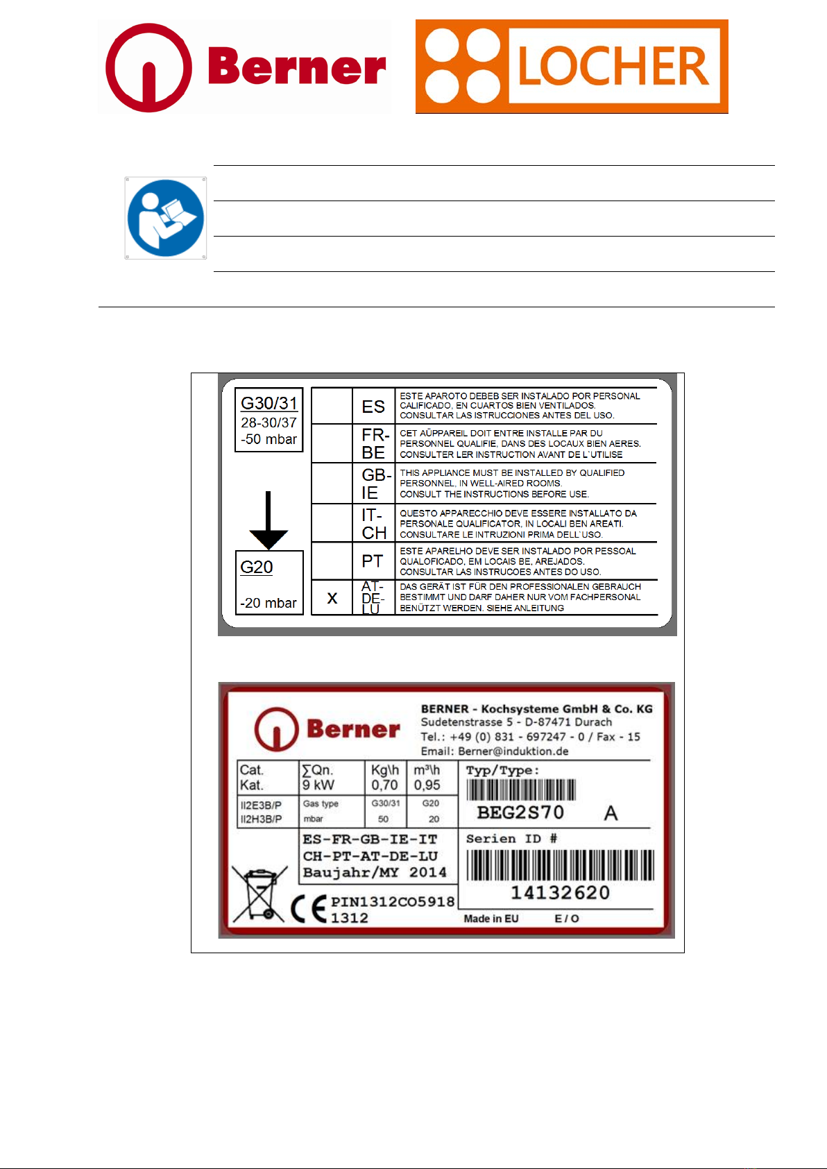
Please determine the exact gas type the unit is set with through the technical data plate placed near the
gas connection and on the packing. The unit must be installed only through authorised, trained and
licensed personnel following the local rules and regulations. Make sure to also follow the rules and
regulations of the local gas supply company. The unit must be operated only by trained personnel.
The gas unit must be installed only in adequately ventilated/aired areas as the contrary could lead to
serious consequences due to combustion residues and/or low oxygen environment air. The installation
room must not be modified after installation of the gas unit. Never ignite the gas unit, if there is a strong
gas smell in the air; open wide windows and doors to change the air inside the room and check the gas
connections for leaks. If you can’t determine the leak position, close the main gas tap and contact your
retailer/wholesaler for a profound analysis of the gas connection system. The unit must be installed only
through authorised, trained and licensed personnel following the local rules and regulations. Make sure to
also follow the rules and regulations of the local gas supply company. Prior to installation, the gas unit
must be checked for dimensions, power and OEM set gas type. If locally there is another gas type
available, only authorised, trained and licensed personnel can substitute the nozzle installed by the OEM.
The exact gas type the unit is set with is indicated on the technical data plate placed near the gas
connection and on the packing. The supply includes also the nozzles for different gas types, enabling the
substitution. Connection to the main gas tap must be carried out exclusively through the OEM gas train.
The gas pressure must be measured and checked. The gas train is equipped with a measuring pipe ( see
image). Loose the screw of the pipe (without removing it) and apply the gas pressure measuring
equipment over it and measure the gas pressure. Tighten the screw after measuring and check if the gas
train is sound by applying soapy water on the joints.
follows

Version 1.3 Page 5 of 20 13.01.2016
Make sure the gas pipe screw is tightened properly after the gas pressure measuring.
Please carry out a gas train and general gas circuit tightness check, in order to find eventual dangerous
leaks. The maximum pressure on the circuit is 50 mbar, but it can be raised ONLY FOR THE TIGHTNESS
CHECK at 150 mbar. Never operate on the gas knob or the main gas tap during the gas circuit tightness
check.
Image
Gas pipe screw for gas pressure measuring (Ø9 mm)
Should there be an electric oven (or any other electric appliance) within the kitchen unit, please carry out
the electrical connection to the mains through authorised and trained personnel following and respecting
the rules and regulations stated in the relative user manual. Every electric appliance must have a separate
and adequately dimensioned power connection. Multipolar protection switches (min. 3 mm contact
openings) and automatic differential protection switches must be installed. The switches must protect
against direct and indirect contact with part under tension and secure the discharge or leakage current
(< 1 mA/kW) respecting the valid rules and regulations.
The unit must be connected to the protective earth (see connecting positions with symbol ), close to
the mains entrance.
The unit must also be included in a potential equalisation system, please connect the unit to the
connector with symbol (eventually with other available units).
follows

Version 1.3 Page 6 of 20 13.01.2016
Hot oil or grease can ignite easily; always use the unit under supervision, in order to limit the risks of fire.
In case of fire, never try to extinguish with water, but use a fire blanket or a cover and close the main gas
tap.
Attention, boiling food can create splashes, dress according to the work safety and its regulations.
In order to save energy, always adapt the pan diameter to the gas burner. The flame shall never burn over
the diameter of the pan, as this may influence the cooking result and the cooking procedure.
Prior to the cleaning of the unit, always turn off all the gas burners and close the main gas tap. Please
allow some time to let the unit cool down, otherwise the detergent could stick to the burner or burner
cover. Never cool down the unit through a water hose or high pressure cleaner. Avoid liquids or food
residues to get inside the burner body. The pan grids or the hotplates can be removed for easy cleaning in
the dishwasher. The troughs shall not be flooded (except the specific models with drain tap). The gas
burner covers can be removed for easy cleaning. Attention, no liquids or food residues shall get inside the
burner body. In order to avoid this, cover up the burner bodies with cling film or aluminium foil. The pan
grids are chromed and can be cleaned in the dishwasher. Never clean the unit and its components with
harsh cleansers and/or abrasives and steel wool pads.
follows

Version 1.3 Page 7 of 20 13.01.2016
3. Functional test
As soon as the unit is professionally and permanently connected to the main gas tap, a gas pressure
measurement must be carried out. A pressure gauge must be connected to the opened pressure
measurement screw (image 1), then open the main gas tap. Please make sure the gas burner covers and
also the pan grids are in place, then open all the burner taps and ignite the burners. The pressure must
comply with the indicated values of the following table:
After the gas pressure test, the unit can be taken into function. At the first ignition after the test, there
might be some residual air in the circuit, which could slightly delay the ignition of the pilot burner flame.
follows
Country
Pressure
(mbar) Category
DE, LU
20-50
II2E3B/P
DK, FI,
SE, IS,
NO, HR,
LT, LV,
EE, SK,
SI, CZ
20-30 II2H3B/P
NL
25-30
II2LL3B/P
FR, BE
20/25-
28/37 II2E+3+
GB, ES,
IT, PT,
IE, GR,
20-
29/37 II2H3+
AT, CH
20-50
II2H3B/P
PL
20-37
II2E3B/P
HU
25-30
II2HS3B/P
CY-MT
30
I3B/P

Version 1.3 Page 8 of 20 13.01.2016
4. Usage of the gas burners
4.1 Ignition of the pilot burner
Open the main gas tap. Turn the knob of the gas burner into position “Ignition” and push the knob
towards the unit. At the same time ignite the pilot burner through a lit match or other ignition means. As
soon as the pilot flame is lit, keep the knob pushed for some seconds, in order to let the pilot
thermocouple warm itself and keep up the pilot flame.
Image
Description
Complete gas burner knob
thermocouple
Burner type D with pilot burner and
thermocouple (example image, pilot burner
and thermocouple are always in the same
position)
follows
Burner off/closed
Ignition
Large flame =
High power
Small flame =
low power

Version 1.3 Page 9 of 20 13.01.2016
4.2 Usage of the gas burners
The power level and intensity of the flame must always be adapted to the pan, the type of preparation
and the quantity of the food. The flame shall never burn over the diameter of the pan; low power with
knob in „small flame“ position, high power with knob in „large flame“ position. If you turn the knob in
position “ignition”, the gas burner turns off, but remains ready to be used, as the pilot burner flame stays
ignited steadily. Never leave any pan unattended on the unit, always assure supervision! In order to save
energy, turn the knob into position “ignition” as soon as possible.
5. Adjustment of the gas burners
The unit is OEM-equipped with the gas type and the values stated in the technical data plate. If locally
there is another gas type available, only authorised, trained and licensed personnel can substitute the
nozzles installed by the OEM. The exact gas type the unit is set with is indicated on the technical data
plate placed near the gas connection and on the packing. The supply includes also the nozzles for
different gas types, enabling the substitution. During the functional test, also the quality of the flame
must be checked. It should have a bluish colour, without yellow tips and must evenly and intensively burn
also at the bottom, close to the burner cover. Should the flame be yellowish, also partially, then the
primary air intake must be adjusted. If there is too much primary air, the flame seems to “solve” from the
burner cover. As soon as the primary air has been set correctly (check the table), the flame must burn
even and steadily during at least 15 minutes of high power usage. Also violent and frequent changeovers
(small, large, small, etc.), operating the knob, shall not interfere with the intensity and pattern of the
flame.
follows

Version 1.3 Page 10 of 20 13.01.2016
6. Malfunctions
Please check the table in case of any malfunction and follow its indications. If the problem should not be
solved or another unstated problem arises, close the main gas tap and contact the retailer/wholesaler for
assistance.
Problem
Possible cause
Correction
Uneven flame
Dirty burner cover
Remove burner cover and clean
thoroughly. Clean burner holes with
toothpick or pin.
Displaced burner cover
Check correct position of burner
cover.
Pilot flame turns off/doesn’t stay on
Thermocouple out of order
Do not use the gas burner and
contact retailer/wholesaler for
assistance.
“Cold” thermocouple
Keep the knob pushed for a longer
time during ignition in order to warn
the thermocouple better.
Hotplate “clatters”/is unstable
Hotplate not positioned correctly
Check positioning
(never on burner type „E“
with 7,5 kW)
Pilot flame cover doesn’t fit
Wrong positioning
The cover has one direction to fit,
turn until it fits.
Wok ring “clatters”/is unstable
Wok ring not positioned correctly
Check positioning
7. Adjustment of the nozzles
The unit is OEM-equipped with the gas type and the values stated in the technical data plate. If locally
there is another gas type available, only authorised, trained and licensed personnel can substitute the
nozzles installed by the OEM. The exact gas type the unit is set with is indicated on the technical data
plate placed near the gas connection and on the packing. The supply includes also the nozzles for
different gas types, enabling the substitution. Please proceed as follows:
•Disconnect unit from electrical power (if applicable)
•Close main gas tap
•Remove knobs
•Remove front panel
follows

Version 1.3 Page 11 of 20 13.01.2016
7.1 Adjustment of the burner nozzle
The nozzles are marked with the relative diameter (punching). Please check the table for the correct
nozzle for every single burner. The nozzle is mounted in the smaller part of the venturi tube made of
aluminium, at the end of the flexible connection tube, in a nozzle holder. Remove the lateral stud screws
and pull out the nozzle holder. Remove the nozzle and replace it with the new, correct nozzle. Make sure
to tighten the nozzle. Insert the nozzle holder and check the primary air distance. Then close the stud
screws. The following table shows the nozzle diameter and primary air distance:
Nozzle
burner C Distance A
Nozzle
burner D Distance A
Nozzle
burner E Distance A
Natural gas H, E, E+
(G20)
20 mbar: 135
25 mbar: 130
5,5 mm
20 mbar: 165
25 mbar: 155
6 mm
20 mbar: 200
25 mbar: 190
7 mm
Natural gas L, LL (G25)
25 mbar: 140
5,5 mm
25 mbar: 170
6 mm
25 mbar: 210
7 mm
Propane G30/G31 50 mbar: 80 6,5 mm 50 mbar: 95 7 mm 50 mbar: 115
Max.
available
Propane G30/G31
28/30 30/37
mbar: 90 6,5 mm
28/30 30/37
mbar: 110 7 mm
28/30 30/37
mbar: 135
Max.
available
Should you change the OEM-installed nozzle, please state the substitution with gas type below and also
mark it on the technical data plate.
follows

Version 1.3 Page 12 of 20 13.01.2016
Image
Description
Nozzle holder
Nozzle
Venturi tube for burner C
Venturi tube for burners D and E
Flexible connection tube
Detail primary air distance A
(in mm)
follows
Distance A

Version 1.3 Page 13 of 20 13.01.2016
7.2 Fine-tune of the gas flame
The fine-tune screw for the gas burner is located in the upper part of the gas tap for each burner. Ignite
the relative burner and fine tune the flame on low power with a small screwdriver. If the burner is
connected to a propane gas line, the screw must be tightened.
Image
Description
Fine-tune screw
Gas tap for each burner
Detail fine-tune screw
Remark: If you use propane G30/G31, then
the screw must be tightened/closed completely.
follows

Version 1.3 Page 14 of 20 13.01.2016
7.3 Adjustment of the pilot burner nozzle
The nozzle is in the pilot burner itself. Remove the pan grid and the screws that fix the pilot in place.
Carefully pull the pilot towards you, through the opening, until the hex screw is accessible. Remove the
hex screw and unscrew the inner screw. That screw is the nozzle itself, it bears the marking of the nozzle
diameter (OEM is 0,21). Don’t lose the spring. Eventually substitute the nozzle and tighten the nozzle
following the table. Put in place the hex screw and tighten it. Insert and fix the pilot burner on the unit
again. Below the table of the pilot burner nozzles:
Burner C
Burner D
Burner E
Natural gas H, E, E+
(G20)
20 mbar: ¼
of a turn
25 mbar: ¼
of a turn
20 mbar: ¼
of a turn
25 mbar: ¼
of a turn
20 mbar: ¼
of a turn
25 mbar: ¼
of a turn
Natural gas L, LL
(G25)
25 mbar: ¼
of a turn
25 mbar: ¼
of a turn
25 mbar: ¼
of a turn
Propane (G30/G31)
50 mbar:
0,21
50 mbar:
0,21
50 mbar:
0,21
Propane (G30/G31) 28/30 30/37
mbar: 0,21
28/30
30/37
mbar: 0,21
28/30
30/37
mbar: 0,21
A ¼ of a turn open with natural gas – closed tightly with propane gas.
Should you change the OEM-installed nozzle, please state the substitution with gas type below and also
mark it on the technical data plate.
follows

Version 1.3 Page 15 of 20 13.01.2016
8. Technical data of the units – External dimensions
Model Width Depth Height
Q.ty
burner C
3,5 kW
Q.ty
burner D
5,5 kW
Q.ty
burner E
7,5 kW
BHG2S70
400
700
Min. 850
1
1
-
BHG4S70
800
700
Min. 850
2
2
-
BHG4S70B
800
700
Min. 850
2
2
-
BHG6S70
1200
700
Min. 850
3
3
-
BHG6S70B
1200
700
Min. 850
3
3
-
BHG4D70
800
700
Min. 850
2
2
-
BHG4D70B
800
700
Min. 850
2
2
-
BHG6D70
1200
700
Min. 850
3
3
-
BHG6D70B
1200
700
Min. 850
3
3
-
BHG2P70
400
700
Min. 850
1
-
1
BHG4P70
800
700
Min. 850
2
-
2
BHG4P70B
800
700
Min. 850
2
-
2
BHG6P70
1200
700
Min. 850
2
2
2
BHG6P70B
1200
700
Min. 850
2
2
2
BHG2S85
400
850
Min. 850
1
-
1
BHG4S85
800
850
Min. 850
1
2
1
BHG4S85B
800
850
Min. 850
1
2
1
BHG6S85
1200
850
Min. 850
1
2
3
BHG6S85B
1200
850
Min. 850
1
2
3
BHG2P85
400
850
Min. 850
-
-
2
BHG4P85
800
850
Min. 850
-
-
4
BHGx...B = with electric oven in the lower compartment.
Should there be an electric oven (or any other electric appliance) within the kitchen unit, please carry out
the electrical connection to the mains through authorised and trained personnel following and respecting
the rules and regulations stated in the relative user manual.

Version 1.3 Page 16 of 20 13.01.2016
Model Width Depth Height
Q.ty
burner C
3,5 kW
Q.ty
burner D
5,5 kW
Q.ty
burner E
7,5 kW
206001
400
600
230/255
1
1
-
206002
800
600
230/255
2
2
-
206003
800
600
Min. 850
2
2
-
206006
400
650
230/255
1
1
-
206007
800
650
230/255
2
2
-
206008
800
650
Min. 850
2
2
-
207000
400
700
Min. 850
1
1
-
207003
800
700
Min. 850
2
2
-
207005
1200
700
Min. 850
3
3
-
207004 *
800
700
Min. 850
2
2
-
207006 *
1200
700
Min. 850
3
3
-
208000
400
850
Min. 850
1
-
1
208001
800
850
Min. 850
1
2
1
208003
1200
850
Min. 850
1
2
3
208002 *
400
850
Min. 850
1
2
1
208004 *
1200
850
Min. 850
1
2
3
20xxxx * = with electric oven in the lower compartment.
Should there be an electric oven (or any other electric appliance) within the kitchen unit, please carry out
the electrical connection to the mains through authorised and trained personnel following and respecting
the rules and regulations stated in the relative user manual.
follows

Version 1.3 Page 17 of 20 13.01.2016
9. Technical data of the units – Nominal power and consumption
Qn kW at max. power / at min. power
Gas type
Natural gas
Propane
Burner C
3,5 / 0,90
Burner D
5,5 / 1,8
Burner E
7,5 / 1,8
Consumption at maximum power
Gas type
Natural gas (G20/G25) m³/h
Propane (G30/G31) Kg/h
Burner C
0,370 / 0,431
0,272 / 0,276
Burner D
0,582 / 0,677
0,427 / 0,434
Burner E
0,794 / 0,923
0,583 / 0,591
10. Technical data of the units – Gas categories
Country
Pressure
(mbar) Category
DE-LU
20-50
II2E3B/P
DK, FI,
SE, IS,
NO, HR,
LT, LV,
EE, SK,
SI, CZ
20-30 II2H3B/P
NL
25-30
II2LL3B/P
FR, BE
20/25-
28/37 II2E+3+
GB, ES,
IT, PT,
IE, GR,
20-
29/37 II2H3+
AT, CH
20-50
II2H3B/P
PL
20-37
II2E3B/P
HU
25-30
II2HS3B/P
CY-MT
30
I3B/P
follows

Version 1.3 Page 18 of 20 13.01.2016
11. Technical data of the units – Electric ovens
Electric oven
Model
Type
W x D x H in mm
Dim. grid/tray in mm
Power upper/lower
part
Power convection
Thermostat
For the correct usage and the functions of the electric ovens, please refer to and carefully follow the
instructions of the separately supplied user manual.
12. Pilot burner protection cover
The pilot burners are supplied with a protection cover made of stainless steel to ensure the cleanliness of
the thermocouple. During operation of the unit, keep the cover in place and clean it if necessary or at
least at the end of the service. To remove, just pull the cover upwards and clean it with soapy water or in
the dishwasher. Then push it back into place, it can be placed only in one direction (see images). The unit
works properly also without the protection cover, but should you lose or break one of them, get in
contact with your retailer/wholesaler for a replacement.
follows

Version 1.3 Page 19 of 20 13.01.2016
13. Hotplate – Optional
The unit can be integrated with a steel hotplate, to ensure usage of the gas burner also like a solid top.
They come in single or double zone size. It is advisable, in case of a single hotplate over a double zone
unit, to add a single pan grid for a correct positioning of the hotplate and an easy and secure usage of the
unit.
The hot plate must never be used on a burner E, only use it with burner C or burner D. The hotplate
must not be used like a griddle/fry top, never put food directly on it. Always use under supervision.
Remove the pan grid and place the hotplate over the burner. Now you can use several pans on the same
zone, up to cover all the surface. The hotplate gets very hot, please be careful. Do not cool it down after
use with a water tap or ice, as it may bend or warp.
Only clean if cold or warm with soapy water and a soft cloth, never use harsh detergents or abrasive
sponges. Use a cloth to dry it after cleaning and store in a dry place if not in use.
Hot plate single size Hot plate doubles size
14. Wok ring – Optional
The unit can be integrated with a wok ring, to ensure usage of the gas burner also like a wok cooker. The
wok ring can be simply added on the pan grid. Now you can use a standard wok pan for diameter 300
mm cook tops (pans can be found in our catalogue). The ring gets very hot, please be careful. Do not cool
it down after use with a water tap or similar, as it may crack or bend. Only clean the ring if cold or warm
with soapy water and a soft cloth, never use harsh detergents or abrasive sponges. Use a cloth to dry it
after cleaning and store in a dry place if not in use.
follows

Version 1.3 Page 20 of 20 13.01.2016
15. Trough with drain hole – Optional
The unit can be equipped with troughs that feature a drain hole. The troughs can be carefully and slightly
flooded with water to ensure easy cleaning. The drain features a tap with security opening to avoid
overflowing of the trough and penetration of liquids through the burner into the gas circuit. Should this
accidentally happen, please close the main gas tap and contact your retailer/wholesaler.
Prior to cleaning the trough, remove solid food residues before draining. Clean with soapy water and a
soft cloth, never use harsh detergents or abrasive sponges. Avoid draining food residues through the
drain tap, as it may clog.
16. Comments – Drawings
This manual suits for next models
36
Table of contents
Popular Cooker manuals by other brands

RM Gastro
RM Gastro 900 Series Instructions for the installation and use

mastro
mastro ABJ0001 Installation, operating and maintenance instructions

AEG
AEG COMPETENCE 2003 F operating instructions

MEL
MEL 16310170 instructions

Bosch
Bosch HXQ38AE5 M Series instruction manual

EAS Electric
EAS Electric EFG555X instruction manual