Besantek RGT-SQ02 User manual

1
RGT-SQ02-wifi Professional Weather Station User Manual
1. Introduction
Thank you for your purchase of the RGT-SQ02-wifi Professional WIFI Wireless Weather sta-
tion. The following user guide provides step by step instructions for installation, operation and
troubleshooting.
2. Warnings
Warning: Any metal object may attract a lightning strike, including your weather station
mounting pole. Never install the weather station during a storm.
Warning: Installing your weather station in an elevated location may result in injury or
death. Safety goes first. Make sure your setup and preparation is secure, and take no risks.
3. Getting Started
The RGT-SQ02-wifi weather station consists of a display console (receiver), a sen-
sor array with Integrated Outdoor Transmitter and mounting hardware.
Parts List
The RGT-SQ02 weather station consists of the following parts (as referenced in Figure 1 ).
QTY Item Image
1
Display Console
Frame Dimensions (LxHxW):
135X26X96mm
LCD Dimensions (LxW): 111 x 75mm
1
Integrated Outdoor Transmitter
Dimensions (LxHxW):
330x150x280mm

2
QTY Item Image
1 Foot Mounting (with pole insert)
Dimensions: 84x 152 x 216mm
1
Mounting Bracket Back Plate (pole
mount)
Dimensions: 76 x 102 x 38mm
1 Mounting Pole
Dimensions: 76 x 76 x 25mm
2 Pole mounting nuts (M3) / bolts Ø3)
4 Pole mounting nuts (M5) / bolts ( Ø5)
4 Tapping screws

3
QTY Item Image
1 Manual
1 Power Adapter
Figure 1
3.2 Recommended Tools
● Precision screwdriver (for small Phillips screws)
● Compass or GPS (for wind direction calibration)
● Adjustable Wrench
● Hammer and nail for hanging remote thermo-hygrometer transmitter.
3.3 Setup of Sensor
The following illustration shows the full segment for Thermo-Hygrometer,WIND,RAIN and
UV INDEX sensor. purposes only, as shown in Figure 2.

4
Figure 2
3.3.1 Insert batteries into the transmitter. Locate the battery cover on the transmitter, push
and open the battery compartment, as show in Figure 3.
Figure 3
Remove the battery cover on the back of the sensor by removing the set screw, as shown in
Figure 4.

5
Figure 4
Inserting 3xAA batteries in the battery compartment, as show in Figure 5.
Figure 5
Close the battery cover. Make sure the gasket (around the battery compartment) is properly
seated in its place prior to closing the door. Tighten the set screw.
Note: Do not install the batteries backwards. You can permanently damage the sensors.
The solar panel does not charge the batteries, so rechargeable batteries are not needed or rec-
ommended.

6
Note: We recommend installing Lithium AA batteries for sensors.
The sensor LED indicator will light for 3 seconds, and then flash once per 16 seconds thereaf-
ter. Each time it flashes, the sensor is transmitting data.
Place the battery cover and push it to close the compartment.
Note: If the sensor does not power up after inserting the batteries, press the reset button
shown in Figure 6.
Figure 6
3.4 Display Console
3.4.1 Display Console Layout
The display console layout is shown in Figure 7
Note: The following illustration shows the full segment LCD display for description pur-
poses only and will not appear like this during normal operation.

7
Figure 7
1.
Out/Indoor
temperature
display
2. WIFI network and AC off icon
3. Out/Indoor humidity units of meas-
ure (%)
4. Out/Indoor humidity HI/LO alarm
icon
5. Out/Indoor humidity display
6. Min/Max reset for 24h icon
7. Maximum recode mode
8.UV Index display
9. Minimum recode mode
10. Sunshine intensity
11.Sunlight units of measure
12. Weather forecast
13.Time alarm icon
14.Time,
date
and
year
15. Rainfall units of measure
16.Rainfall HI alarm icon
17. Rainfall display (RATE, 24h, WEEK,
MONTH, TOTAL)
18. Wind speed average display
19. Wind gust display
20. Wind speed units of measure
21.Feels like HI/Lo alarm icon
22. Wind direction
23. Dew point and AT (Apparent Tempera-
ture) display icon
24. Integrated outdoor transmitter Low pow-
er indicator
25.Out/Indoor temperature units (°F or °C)
26.Out/Indoor temperature HI/LO alarm icon
3.4.2 Display Console Set Up
It is recommended to plug in the power supply to reduce the battery
consumption and extend the service life.

8
Note: The sensor array must be powered and updating before powering up the console, or the
console will time out searching for the sensors. Power the console last.
Make certain the weather station sensor array is at least 3m away from the console and within
30m of the console. If the weather station is too close or too far away, it may not receive a proper signal.
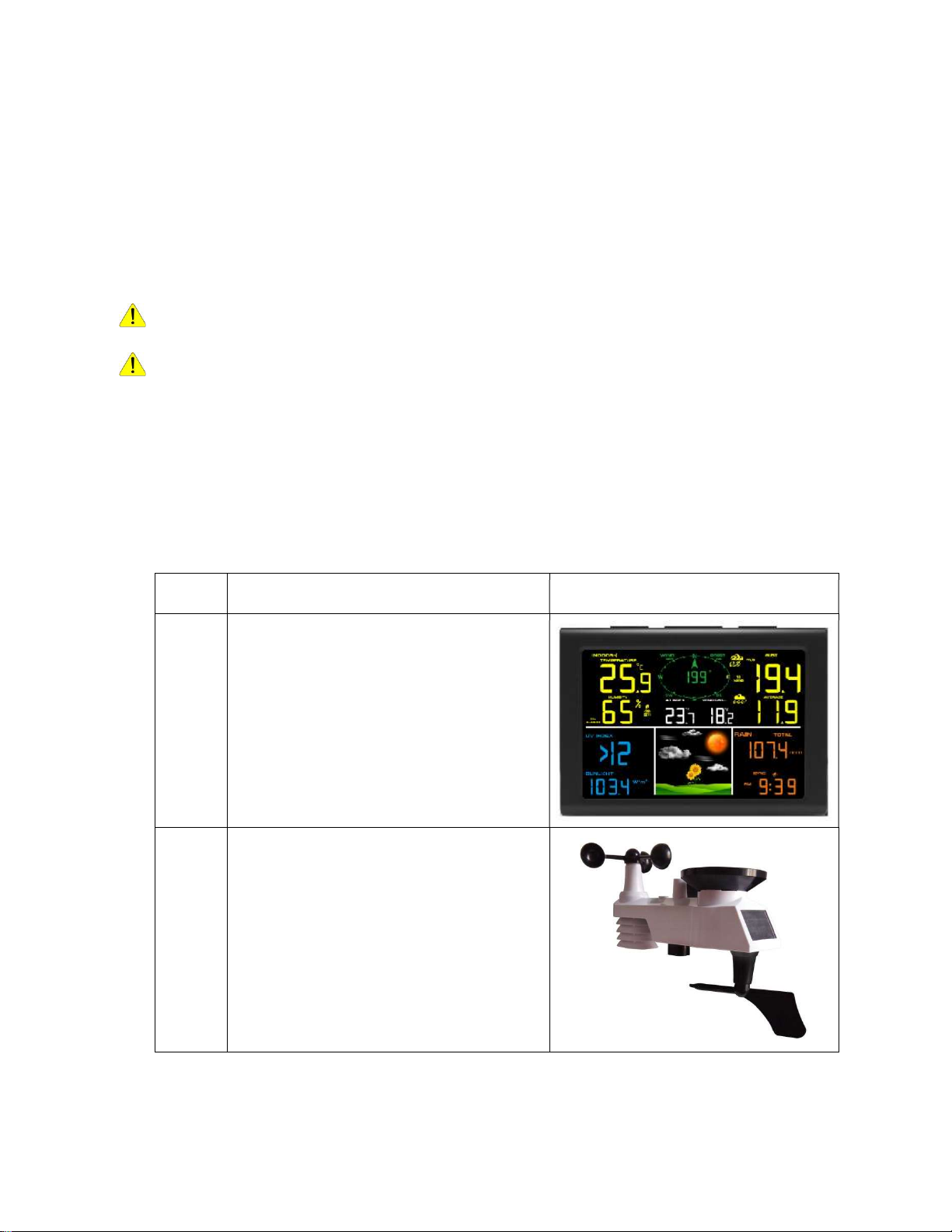
Remove the battery case on the back of the display, as shown in Figure 11. Insert three AAA (alkaline or
lithium)) batteries in the back of the display console. The display will beep once and all of the LCD seg-
ments will light up for a few seconds to verify all segments are operating properly.
Note: The character contrast is best from a slightly elevated viewing angle.
Figure 8
Replace the battery case, and fold out the desk stand and place the console in the upright posi-
tion.
The unit will instantly display indoor temperature, humidity, tendency, and time. The wind
speed, wind gust, wind direction, rain, UV/Sunlight, Integrated outdoor temperature and hu-
midity will update on the display within a few minutes. Do not Press any menu buttons until
the outside transmitter report in, otherwise the outdoor sensor search mode will be terminated.
When the outdoor transmitter data has been received, the console will automatically switch to
the normal mode from which all further settings can be performed.
While in the search mode, the remote search icon will be constantly displayed.
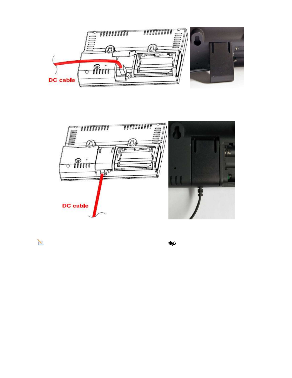
Note: The power adapter is intended to be correctly oriented in a vertical or floor mounted
position. The prongs are not designed to hold the plug in place if it is plugged into a ceiling,
under-the-table or cabinet outlet.

9
Figure 12
1: Fold out the desk stand and see DC jack on the left; as shown in Figure 13
Figure 13
2: Insert the DC plug correctly; as shown in Figure 14
Figure 14
3: If you want to put it on a table or cabinet, opened the desk stand and turn the DC plug
up until 90 degrees; as shown in Figure 15

10
Figure 15
4: If you want to hang on the wall, turn the DC plug down until 0 degrees and closed the
desk stand; as shown in Figure 16
Figure 16
Note: If the power adapter is not plugged in, the icon will display.
3.4.2 Sensor Operation Verification
The following steps verify proper operation of the sensors prior to installing the sensor array.
1. Verify proper operation of the rain gauge. Tip the sensor array back and forth several times.
You should hear a “clicking” sound within the rain gauge. Verify the rain reading on the dis-
play console is not reading 0.00. Each “click” represents 0.3mm of rainfall.
2. Verify proper operating of the wind speed. Rotate the wind cups manually or with a constant
speed fan. Verify the wind speed is not reading 0.0.
3. Verify proper operation of the indoor and outdoor temperature. Verify the indoor and out-
door temperature match closely with the console and sensor array in the same location
(About 3m apart). The sensors should be within 2°C (the accuracy is ±1°C). Allow about 30
minutes for both sensors to stabilize.
4. Verify proper operation of the indoor and outdoor humidity. Verify the indoor and outdoor
humidity match closely with the console and sensor array in the same location (about 3m

11
apart). The sensors should be within 10% (the accuracy is ± 5%). Allow about 30 minutes for
both sensors to stabilize.
4.Weather Station Installation
4.1Pre Installation Check. Before installing your weather station in the permanent loca-
tion, we recommend operating the weather station for one week in a temporary location
with easy access. This will allow you to check out all the functions, ensure proper operation,
and familiarize you with the weather station and calibration procedures. This will also allow
you to test the wireless range of the weather station.
4.2 Location Survey
Perform a site survey before installing the weather station. Consider the following:
1. You must clean the rain gauge once per year and change the batteries every one years.
Provide easy access to the weather station.
2. Avoid radiant heat transfer from buildings and structures. In general, install the sensor ar-
ray at least 5’ from any building, structure, ground, or roof top.
3. Avoid wind and rain obstructions. The rule of thumb is to install the sensor array at least
four times the distance of the height of the tallest obstruction. For example, if the building is
6m tall, install 4 x 6m = 24m away. Use common sense. If the weather station is installed next
to a tall building, the wind and rain will not be accurate.
4. Wireless Range. The radio communication between receiver and transmitter in an open field
can reach a distance of up to 100 m, providing there are no interfering obstacles such as build-
ings, trees, vehicles, high voltage lines. Wireless signals will not penetrate metal buildings.
Most applications will only reach 30m due to building obstructions, walls and interference.
5. Radio interference such as PCs, radios or TV sets can, in the worst case, entirely cut off ra-
dio communication. Please take this into consideration when choosing console or mounting
locations.
4.3 Best Practices for Wireless Communication
Wireless communication is susceptible to interference, distance, walls and metal barriers. We
recommend the following best practices for trouble free wireless communication.
1. Electro-Magnetic Interference (EMI). Keep the console several feet away from computer
monitors and TVs.
2. Radio Frequency Interference (RFI). If you have other 433 MHz devices and communica-
tion is intermittent, try turning off these other devices for troubleshooting purposes. You may
need to relocate the transmitters or receivers to avoid intermittent communication.
3. Line of Sight Rating. This device is rated at 100 m line of sight (no interference, barriers or
walls) but typically you will get 30 m maximum under most real-world installations, which in-
clude passing through barriers or walls.
4. Metal Barriers. Radio frequency will not pass through metal barriers such as aluminum sid-
ing. If you have metal siding, align the remote and console through a window to get a clear line
of sight.
The following is a table of reception loss vs. the transmission medium. Each “wall”or obstruc-
tion decreases the transmission range by the factor shown below.
Medium RF Signal Strength Reduction

12
Glass (untreated) 5-15%
Plastics 10-15%
Wood 10-40%
Brick 10-40%
Concrete 40-80%
Metal 90-100%
5.Final Installation of Sensors
Integrated outdoor transmitter installation.
Professional Wireless Weather Station can be used in both the Northern and Southern Hemi-
spheres.
Prior to installation, you will need to calibrate the wind direction.
5.1. Northern Hemispheres (NOR).
The cardinal directions (N, S, E, W) molded on the body of the outdoor sensor are indicators
for the Northern Hemisphere only.
Step 1:There is a “S” indicator on the wind vane that indicates South, as shown in Figure 13.
Align this “S” marker in the direction of South.
Step 2: Console operation is set to Northern Hemispheres ( NOR in the time area) in Location
division.
Note: There are four alphabet letter of “N”,”E”,”S”and “W” around the wind direction,
representing for the direction of North, East, South and West. Wind direction sensor has to be
adjusted so that the directions on the sensor are matching with your real location. Permanent
wind direction error will be introduced when the wind direction sensor is not positioned cor-
rectly during installation.

13
Northern Hemispheres
Southern Hemispheres
Figure 13
5.2. Southern Hemispheres (SOU).
For Southern Hemisphere installations, ignore these(N, S, E, W) and face the solar panel to
the North (and in a sunny position) when installing the Integrated outdoor transmitter.
Step 1: Install the Integrated outdoor transmitter and face the solar panel North.
Step 2: Console operation is set to Southern Hemispheres ( SOU in the time area) in Location
division.
Note: Console has to be location division setting so that the directions on the sensor are
matching with your real location. Permanent wind direction error(read approximately 180º)
will be introduced when the wind direction sensor is not positioned correctly during installa-
tion.
Fasten the integrated transmitter to mounting pole brackets with foot-mounting, two ¢3 bolts
and M3 nuts , as shown in Figure 14

14
Figure 14
Tighten the mounting pole to your existing mounting pole with the four¢5 Bolts and M5 Nuts
assembly, or fix on the wall with four tapping screw, as shown in Figure15.

15
Figure 15

16
6.Low Battery Icon
A low battery indicator icon is shown in the display window for Integrated outdoor transmitter.
When the low battery icon appears (the battery voltage is lower than 3.6V), replace the batter-
ies in the sensor with fresh batteries. Be sure to never mix old and new batteries, and never mix
battery types such as alkaline and lithium together.
7.Console Operation
Note: The console has five keys for easy operation: SET key and ALARM key on the
right side, MIN/MAX/-key, SNOOZE/LIGHT and CHANNEL/+ key on the top.
7.1 Quick Display Mode
Note: To exit the Quick Display Mode at any time, press the SNOOZE key of the display
console.
While in Normal Mode, press (do not hold) the SET key to enter the Quick Display Mode as
follows:
once for time, date and year,
twice for out or indoor temperature and humidity alarm on/off view
three for rainfall.
four for outdoor dew point temperature
Five for wind average
1.Time, Date and Year. Press the CHANNEL/+ or MIN/MAX/- key to toggle between time,
date and year.
2.Indoor Temperature. Press the CHANNEL/+ or MIN/MAX/- key to toggle between
out/indoor for temperature and humidity alarm on/off view
3.Rainfall. Press the CHANNEL/+ or MIN/MAX/- key to toggle between rate, 24h, week,
month and total.
To clear the total rain, press the CHANNEL/+ or MIN/MAX/- button until total rain is dis-
played. The total rain will flash. Press and hold the SET button for five seconds until total
rain reads 0.0.
4. Dew Point. Press the CHANNEL/+ or MIN/MAX/- key to toggle between outdoor AT
(Apparent Temperature) and dew point.
5.Wind Average. Press the CHANNEL/+ or MIN/MAX/- key to toggle between cur-
rent,2mins and 10 minutes.
7.2 Set (Program) Mode
While in Normal Mode, press and hold the SET key for at least three seconds to enter the Set
Mode. The first setting will begin flashing. You can press the SET key again to skip any step,
as defined below.
Note: In the Set mode, press the [+] key or [-] key to change or scroll the value. Hold the
[+] key or [-] key for three seconds to increase/decrease rapidly.
Note: To exit the Set mode at any time, press the SNOOZE button of the display console.

17
1. Time SYNC(default: ON).Press the SET key again to set the network time sync. Press the
[+] key or [-] key to switch between SYNC time ON and SYNC time OFF of measure.
2. 12/24 Hour Format (default: 24h):.Press the SET key again to adjust the 12/24 hour for-
mat setting (FMT). Press the [+] key or [-] key to change between 12 hour and 24 hour
format.
3. Change Hour. press the SET key again to set the hour. Press the [+] key or [-]key to adjust
the hour up or down. Note the PM icon is present during afternoon hours.
4. Change Minute. Press the SET key again to set the minute. Press the [+] key or [-] key to
adjust the minute up or down.
5. Date Format (default: DATE): Press the SET key again to enter the day/month format
mode. Press the [+] key to switch between MM-DD, DD-MM.
6. Change Month. Press the SET key again to set the calendar month. Press the [+] key or [-]
key to adjust the calendar month.
7. Change Day. Press the SET key again to set the calendar day. Press the [+] key or [-] key
to adjust the calendar day.
8. Change Year. Press the SET key again to set the calendar year. Press the [+] key or [-]
key to adjust the calendar year.
9. Max/Min Clearing (default: ON). Press the SET key again to set the max/min clearing
mode (CLEARS). The Max/Min can be programmed to clear daily (at midnight) or manu-
ally. Press the [+] key or [-] key to switch between “Clears 24h” and Clears Manually.
10. Temperature Units of Measure (default: °C):. Press the SET key again to change the
temperature units of measure (the UNITSET icon will be displayed). Press the [+] key or [-
] key to switch between °F and °C units of measure.
11. Wind Speed Units of Measure (default: m/s). Press the SET key again to change the
wind speed units of measure . Press the [+] key or [-] key to toggle the wind speed units be-
tween m/s,ft/s, bft, knots, mph or km/h.
12. Rainfall Units of Measure (default: mm). Press the SET key again to change the Rainfall
units of measure. Press[+] key or [-] key to toggle the rainfall units between mm and inch.
13. Pressure Threshold Setting (default level 2). Press the SET(MODE) key again to change
the pressure threshold. Press the [+] key or [-] key to change pressure threshold 2
mbar/hour to 4 mbar/hour.(For detailed information of this part please refer to 15.5)
14. Weather Icons Setting (default: partly cloudy). Press the SET key again to change the
initial weather icon. Press the [+] key or [-] key to select the initial weather icon of Sunny,
Cloudy, Partly Cloudy or Rainy. (For detailed information of this part please refer to 15.1
and 15.2)
15. Sunlight Display Units(default: W/㎡). Press the SET key again to change the sunlight
units of measure. Press the [+] key or [-] key to toggle the sunlight units between , W/㎡,
fc or lux.
16. Location division.(default: Northern Hemisphere).Press the SET(MODE) key again to
change the location division. Press the [+] key or [-] key to toggle the sunlight units North-
ern Hemisphere (NOR)or Southern Hemisphere(SOU).(refer to 5.0 Final Installation of In-
tegrated outdoor transmitter)
7.3 Sensor Search Mode
If Outdoor sensor loses communication, dashes (--.-) will be displayed.

18
To reacquire the lost signal, press and hold the CH/+ button for 3 seconds to enter the sensor
search mode.
7.4 Reset Min/Max record
Note: The minimum and maximum value of all channels will be cleared in the reset mode.
In normal mode, press (do not hold) the MIN/MAX/-key, the MAX icon will be displayed in
UV INDEX area. Press the SET key to view max values of rainfall (rate, 24h, week or
month) , OUT or Indoor temperature and humidity ,outdoor temperature and humidity(AT or
dew point).
Press the MIN/MAX/- key for three seconds(and the CLR character is flashing in time area) to
clear all max values. the rainfall, wind speed, wind gust, Out and indoor temperature and hu-
midity maximum values. The maximum values will now display the current values).
Press the MIN/MAX/- key again (do not hold), the MIN icon will be displayed. Press the SET
key to view min values of out/indoor temperature/humidity and outdoor (AT or dew point)
Press the MIN/MAX/- key for three seconds(and the CLR character is flashing in time area)
to clear all min values.(Indoor and out temperature and humidity minimum values. The mini-
mum values will now display the current values).
Press the SNOOZE key to exit the min/max checking and cleaning mode, return to normal
display mode.
7.6 Snooze Mode
If the alarm sounds, and you wish to silence the alarm, press the SNOOZE key, the backlight
will turn on. The alarm icon will continue to flash and the alarm will silence for five minute.
press any key (MIN/MAX/+ ,SET, ALARM,CHANNEL/+) to permanently exit the Snooze
mode.
7.7 Back light Mode
If the LED is off, Press the SNOOZE button once. The backlight will turn on for five seconds,
and if no operation is performed for three seconds, the backlight will turn off.
The backlight operation is different when operating on batteries to save power.
ADJUSTABLE BACKLIGHT BRIGHTNESS
There are 3 levels of brightness of backlight. When the backlight is on press SNOOZE key to
switch between the 3 levels.
When backlight is off, press and hold the SNOOZE key for two seconds, the backlight will
turn on permanently
To turn off the backlight at any time press and hold the SNOOZE key for two seconds, the
backlight will turn off (visible after 10 seconds).

19
Note: If plugged into AC power, the backlight will remain on. It is not recommended leav-
ing the backlight on for a long period of time when operating on batteries only, or the batteries
will run down quickly.
8.Alarm Mode
The RGT-SQ02 includes the following alarms:
Time
Out Temperature
Out Humidity
Out AT (Apparent Temperature)
Out Dew Point
Out Feels Like Temperature
Wind Gust
Wind Average
Rate Rainfall
24 Hour Rainfall
Indoor Temperature
Indoor Humidity
8.1 Alarm Operation
When an alarm condition is exceeded, the alarm icon will flash (visual) and the alarm beep-
er will sound (audible). To silence the beeper, press any key.
8.2 Viewing the High and Low Alarms
To view the current alarm settings, press the ALARM key to enter the alarm mode. ALARM
will be displayed in the time area. At the same time Alarm time parameters of out/indoor tem-
perature/humidity, rain rate, AT, feels like, wind gust, wind average, and dew point are dis-
played.
Press ALARM key again to view the LOW alarms along with the alarm clock time the same
way HI alarms.
Press the SNOOZE key at any time to return to the normal mode.
8.3 Setting the Alarms
Press ALARM key to enter the alarm mode.
Press and hold the SET key for three seconds. The first alarm parameter will begin flashing
(alarm hour).
To save the alarm setting and proceed to the next alarm parameter, Press (do not hold) the SET
key.

20
To adjust the alarm parameter, press the [+] or [-] key to increase or decrease the alarm set-
tings, or press and hold the [+] or [-] key for three seconds to increase or decrease the alarm
settings rapidly.
Press the ALARM key to turn on (the alarm icon will appear) and off the alarm.
Press the SNOOZE key once at any time to return to the normal mode. After 30 seconds of
inactivity, the alarm mode will time out and return to normal mode.
The following is a list of the individual alarm parameters that are set (in order):
1. Alarm hour
2. Alarm minute
3. Outdoor temperature high alarm
4. Outdoor temperature low alarm
5. Outdoor humidity high alarm
6. Outdoor humidity low alarm
7. Outdoor AT high alarm
8. Outdoor AT low alarm
9. Outdoor dew point high alarm
10. Outdoor dew point low alarm
11. Outdoor feels like high alarm
12. Outdoor feels like low alarm
13. Wind Gust high alarm
14. Wind Average high alarm
15. Rainfall (RATE) high alarm
16. Rainfall (24h) high alarm
17. Indoor temperature high alarm
18. Indoor temperature low alarm
19. Indoor humidity high alarm
20. Indoor humidity low alarm
Note: To prevent repetitive temperature alarming, there is a 0.5 °C tolerance band. For ex-
ample, if you set the high alarm to 26.7 °C and silence the alarm, the alarm icon will continue
to flash until the temperature falls below 26.2°C, at which point, the alarm will reset and must
increase above 26.7 °C to activate again.
Note: To prevent repetitive alarming of humidity, there is a 4% tolerance band in humidity
alarm. For example, if you set the high alarm to 60% and silence the alarm, the alarm icon will
continue to flash until the humidity falls below 56%, at which point, the alarm will reset and
must increase above 60% to activate again.
9. WiFi Connection Status
When the console successfully connects to your Wi-Fi router, the Wi-Fi signal icon
will appear on the LCD display (behind the Outdoor humidity). If the Wi-Fi signal is not stable
or the console is trying to connect to the router, the icon will flash. If the icon disappears, it
means the console is not connected to the Wi-Fi router.
Table of contents
Popular Weather Station manuals by other brands

Oregon Scientific
Oregon Scientific WMR200A user manual

La Crosse Technology
La Crosse Technology WS-2315CH Operation manual

Hama
Hama EWS-1200 operating instructions

Logia
Logia LOWSC715FWB10 user guide

Holman
Holman ASPECT Wi-Fi Solar Pro WS5091W-MKii user guide

UNITEC Climate
UNITEC Climate E0106 owner's manual