Bespoke Channel Lok-II User manual

No Diving or Jumping. Observe all Safety Rules.
1-1
Sunray - Channel Lok-II
Oval Pools
❏Part No. 1920583 rev. 0
1
Pool Component Installation
Manual
General Instructions
SECTION
Safety Rules For Pool Owners
This manual must be left with the pool owner
Your pool contains a large quantity of water, and is deep enough to present inherent
dangers to life and health unless the following safety rules are strictly observed. First-
time users run the highest risk of injury. Make sure everyone understands all safety
rules before entering the pool. Post NO DIVING and NO JUMPING signs beside the pool.
For additional safety information please read the enclosed booklet The Sensible Way
To Enjoy Your Aboveground/Onground Swimming Pool.
1. No Jumping or Diving
The top rail of your pool is not a walkway and must not be used for jumping or diving.
Do not permit jumping or diving into the pool from a deck or the top rail of the pool.
Diving or jumping into the pool can result in serious injury.
2. Never use the Pool Alone
Never permit the pool to be used unless it is attended by at least one person other than
the bather. Someone should always be available to lend assistance in an emergency.
3. Never Leave Children Unattended
Never leave a child alone and unsupervised in or near the pool—not even for a sec-
ond. There is no substitute for constant adult supervision.
4. No “Rough-housing”
Do not permit “rough-housing” in and around your pool. Surfaces can become slippery
and hazardous when wet.
5. Light the Pool at Night
If the pool is used after dusk, adequate lighting must be provided. Illumination in the
pool area must be sufficient to clearly judge pool depth and all features in and around
the pool. For lighting recommendations, consult your local licensed electrical
contractor.
6. Restrict Access to the Pool
Do not leave chairs or other furniture beside the pool that could be used by a child to
climb up into the pool. Ladders must be removed whenever the pool is unattended. A
fence with a lockable gate around the pool or yard is strongly recommended and may
be required by law in some jurisdictions.
7. No Alcohol or Drugs
The use of alcohol or drugs does not mix with pool activities. Persons who have been
drinking alcohol or using any drugs should not be allowed in the pool, and should be
carefully supervised in the surrounding area.
8. Keep Your Pool Clean and Sanitary
Your filter system will remove suspended particles from the water and the surface
skimmer will remove insects, leaves and other debris from the water surface. Use the
correct pool chemicals as directed to destroy harmful bacteria and prevent formation
of algae. Remember, unsanitary water is a serious health hazard.

No Diving or Jumping. Observe all Safety Rules.
A. Introduction to Installing your Pool
Read all instructions completely before you begin.
These instructions explain how to install your pool. Simply follow the step-
by-step directions. Start with this part, SECTION 1 and use the other instruc-
tions, SECTION 2 to 4to put together your entire pool.
SECTIONS 1, 2 and 3have information for several different pool sizes and
styles; follow the instructions carefully to make sure you use the informa-
tion that apply to your specific pool.
SECTION 1 also has Safety Rules and instructions to help you keep your
pool clean and in good shape, year after year. Be sure to read the Safety
Rules, and make sure everyone who uses your pool reads and under-
stands them.
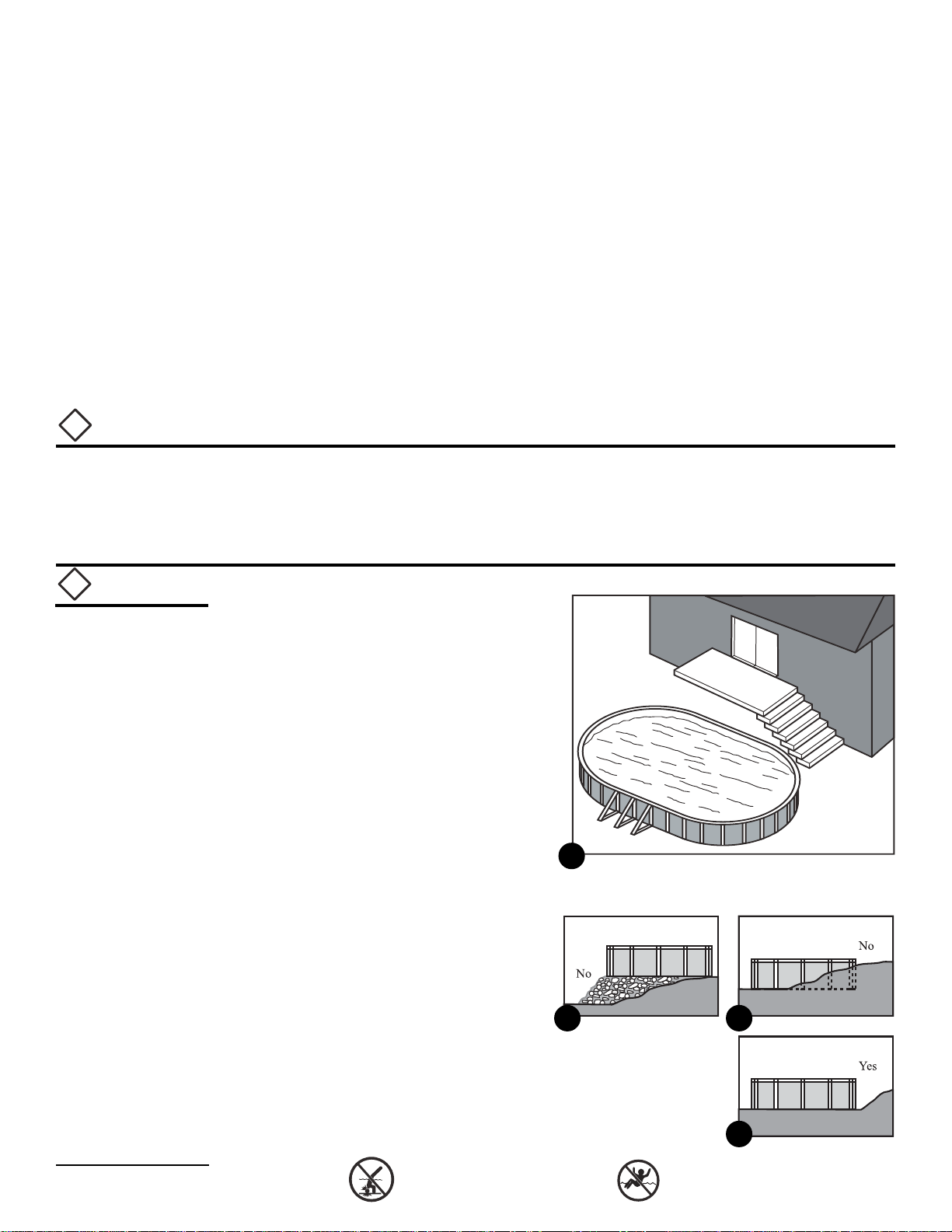
B. Determine a Location for your Pool
1. The Terrain
Pay special attention to choos-
ing the right location for your
pool:
• Choose a large area, as flat
and level as possible.
• Choose a spot on dry, firm
earth—do not install the pool
on asphalt, tar paper, sand,
gravel, peat moss, wood or
chemically treated soil.
• Check with your pool dealer
to see if Nut Grass grows in
your area. This type of grass
may grow up through your
pool liner. Your dealer will be
able to advise how best to
treat the site.
• Sloped areas will need to be
made level by digging away
high spots, not by filling low
spots—be prepared to hire
earth-moving equipment if
necessary.
1
2 3
4
1-2
!
Important Note:
This pool has been designed to allow for installation on a level concrete pad. The pad must be a mini-
mum of 3" (8 cm) thick and poured onto solid undisturbed ground.
Note: A brick sand or styrofoam bottom & a brick sand or fine earth cove still must be installed over the
concrete foundation to protect the liner. This is detailed in Section 2 of the pool frame installation
manual.
!
Important Note:
Ground prepara-
tion is one of the
most important
steps in the instal-
lation process. A
proper foundation
will ensure the rest
of the pool assem-
bly goes smoothly
and that no prob-
lems will occur
when the pool is
filled with water.
Open all of the
frame cartons and
read all of the
instructions before
you begin. Be sure
to read Section 2
and get a com-
plete overview of
the pool base and
buttress assembly
before starting the
ground prepara-
tion.

No Diving or Jumping. Observe all Safety Rules.
2. Things to Avoid
Do not locate your pool near or
on any of the following:
• Overhanging tree branches.
• Overhead wires, clotheslines.
• Buried pipes and wires—
contact your gas, electric and
telephone utilities to find
buried pipes and wires
before you dig.
• Hilly and uneven terrain.
• Areas with poor drainage.
• Grass, stones and roots. Grass
will rot underneath the pool
liner, and stones and roots
will damage the pool liner.
• Areas recently treated with oil-based weed killers, chemicals or ferti-
lizers.
3. Plan Ahead
• Will you be adding an adjacent deck later? Be sure to leave room.
• Will you be using pool accessories or other appliances that need
electricity or gas? Locate your pool near these services or plan to
have them installed later by a licensed contractor.
C. Prepare the Foundation of your Pool
1. Choose the Correct Ground Preparation Drawing
a. Choose the drawing that matches your pool size from the five plan
drawings below. This drawing will have all of the necessary dimen-
sions for the ground preparation instructions that follow.
1-3
15 x 30 Oval Pool
Dimensions
R90" (229 cm)
S102" (259 cm)
L90" (229 cm)
M30-1/2" (77 cm)
N59-1/2" (151 cm)
P180" (457 cm)
W134" (340 cm)
X90" (229 cm)
Y127-1/4" (323 cm)
Z161-1/2" (410 cm)
BB
G
G
KJ
HI
R
R
S
S
X
XY
YZ
Z
N
NMM
P
P
L
L
F
F
E
EDD
A
A
C
C
W
W
Measuring StakesMeasuring Stakes
Centre PointCentre Point
CentrelineCentreline
Pool AreaPool Area
Pool WallPool Wall
Clearance AreaClearance Area
!
Important:
When locating the
centreline of the
pool, be sure to
take into consid-
eration any struc-
tures (deck, patio,
house) or relevant
items (change
rooms, gazebo,
etc.) that the pool
may need to line
up with and en-
sure that the pool
is in the most
visual pleasing
location for your
property.
5 6
7

No Diving or Jumping. Observe all Safety Rules.
1-4
15 x 24 Oval Pool
Dimensions
R90" (229 cm)
S102" (259 cm)
L54" (137 cm)
M30" (76 cm)
N48" (122 cm)
P108" (274 cm)
W134" (340 cm)
X90" (229 cm)
Y105" (267 cm)
Z144-1/2" (367 cm)
12 x 24 Oval Pool
Dimensions
R72" (183 cm)
S84" (213 cm)
L72" (183 cm)
M24" (61 cm)
N48" (122 cm)
P144" (366 cm)
W116" (295 cm)
X72" (183 cm)
Y101-3/4" (258 cm)
Z136-1/2" (347 cm)
12 x 18 Oval Pool
Dimensions
R72" (183 cm)
S84" (213 cm)
L36" (91 cm)
M36" (91 cm)
P72" (183 cm)
W116" (295 cm)
X72" (183 cm)
Y80-1/2" (204 cm)
Z121-1/2" (309 cm)
BB
G
G
R
R
S
S
X
XY
Y
N
NMM
P
P
L
L
F
F
E
EDD
A
A
C
C
KJ
HI
Z
ZW
W
Measuring StakesMeasuring Stakes
Centre PointCentre Point
CentrelineCentreline
Pool AreaPool Area
Clearance AreaClearance Area
Pool WallPool Wall
BB
G
G
R
R
S
S
X
XY
Y
N
NMM
P
P
L
L
F
F
E
EDD
A
A
C
C
KJ
HI
Z
ZW
W
Measuring StakesMeasuring Stakes
Centre PointCentre Point
CentrelineCentreline
Pool AreaPool Area
Clearance AreaClearance Area
Pool WallPool Wall
BB
G
G
R
R
S
S
X
XY
Y
M
M
P
P
L
L
F
F
E
EDD
A
A
C
C
KJ
HI
Z
ZW
W
Measuring StakesMeasuring Stakes
Centre PointCentre Point
CentrelineCentreline
Pool AreaPool Area
Clearance AreaClearance Area
Pool WallPool Wall

No Diving or Jumping. Observe all Safety Rules.
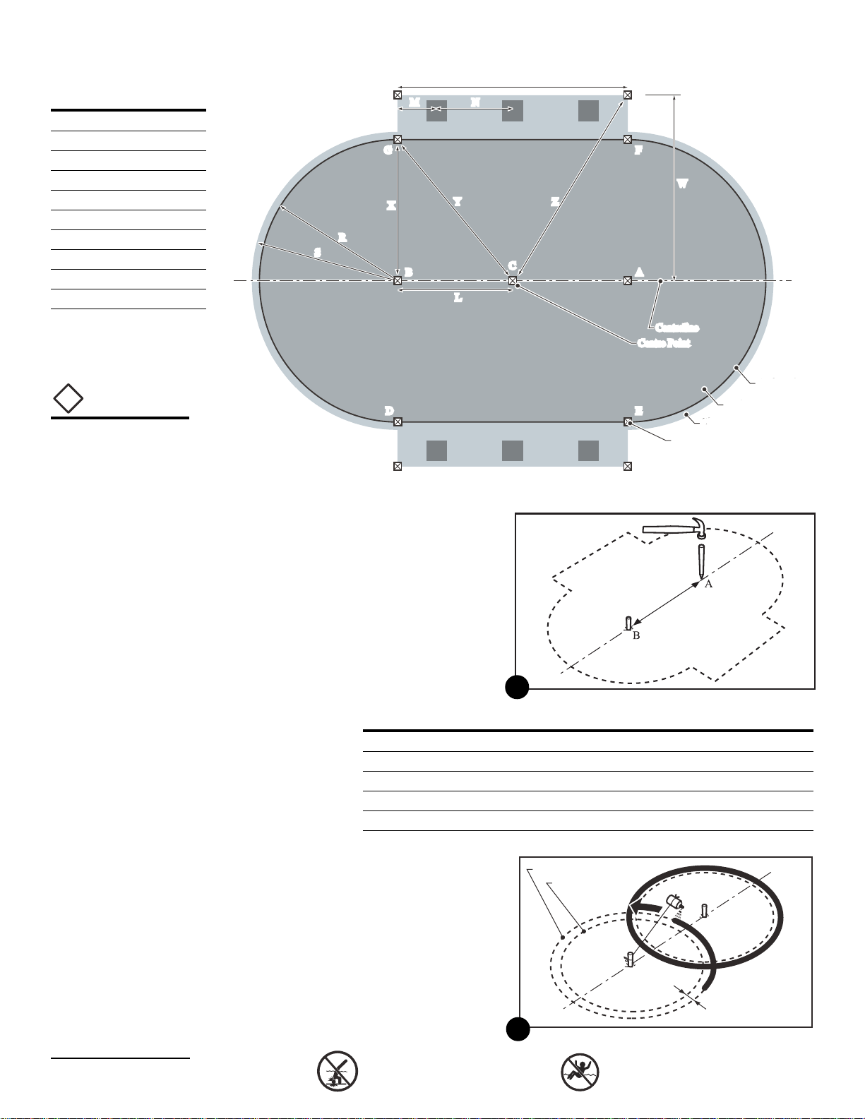
2. Mark out the Area
a. Drive two pegs (A) and (B) into
the ground. These pegs will
both be on the centreline of
your pool. Choose the right
distance between them from
the chart below. Note: Dis-
tance Ato Bis equal to di-
mension Pon the pool draw-
ings above.
Pool Size Distance between two pegs (A) and (B)
12' x 18' 72" (183 cm)
12' x 24' 144" (366 cm)
15' x 24' 108" (274 cm)
15' x 30' 180" (457 cm)
18' x 33' 180" (457 cm)
b. Use a length of string tied
between peg (A) and a can of
spray paint, and mark a
circle on the ground. Next, do
the same for peg (B). Choose
the length of string you need
for your pool from the chart
on the next page. The circles
will be 12" (30 cm) bigger all
round than the pool.
1-5
8
18 x 33 Oval Pool
Dimensions
R108" (274 cm)
S120" (305 cm)
L90" (229 cm)
M30-1/2" (77 cm)
N59-1/2" (151 cm)
P180" (457 cm)
W152" (386 cm)
X108" (274 cm)
Y140-5/8" (357 cm)
Z176-5/8" (449 cm)
BB
G
G
R
R
S
S
X
XY
Y
N
NMM
P
P
L
L
F
F
E
EDD
A
A
C
C
KJ
HI
Z
Z
WW
Measuring StakesMeasuring Stakes
Centre PointCentre Point
CentrelineCentreline
Pool AreaPool Area
Clearance AreaClearance Area
Pool WallPool Wall
B
A
Size of foundation area
Size of pool
12" (30 cm)
9
!
Important:
Determine the
location of your
pool. Make sure
you have the
proper distances
away from any
adjacent
structures (i.e.
fences, house etc.).
Contact local
authorities for this
information and
any additional
requirements
governing the
installation of a
pool in your area.
By using the dis-
tances provided
by local
authorities and
adding them to
dimension Sfrom
the drawings
above, you can
calculate the
location of the
centreline of the
pool.

No Diving or Jumping. Observe all Safety Rules.
Pool Size Length of String
12' x 18' 84" (213 cm)
12' x 24' 84" (213 cm)
15' x 24' 102" (259 cm)
15' x 30' 102" (259 cm)
18' x 33' 120" (305 cm)
c. Join the two pegs (A) and (B)
with a piece of string. Use this
string as a guide to paint your
centreline on the ground with
the can of spray paint.
d. Drive a flat-topped stake (C)
exactly halfway between the
two pegs (A) and (B) on the
centreline. Stake (C) will mark
the exact centre point of your
pool. The stake must be at
least 1" (25 mm) square and
6" (15 cm) long. Drive it down
flush with the ground surface.
e. Replace the two pegs (A) and
(B) with two more flat-topped
stakes. Drive them down flush
with the ground surface.
f. Join the two circles with
straight lines to make an oval.
Use pegs and a piece of string
as a guide for the can of
spray paint.
1-6
10
B
A
C
11
!
Important:
Measure carefully
to make sure the
centre stake (C) is
in the correct
location, exactly
halfway between
pegs (A) and (B).
You will use stake
(C) later as a
reference point for
other measure-
ments.
B
C
A
12

No Diving or Jumping. Observe all Safety Rules.
g. Mark areas along both
straight sides of your oval. Use
pegs and string as a guide for
the can of spray paint to
mark straight lines. Use the
chart below to find the
correct width W from the
centreline of the pool. The
ends of the side areas should
line up squarely with stakes
(A) and (B).
Pool Size Distance from Centreline for Side Area
W
12' x 18' 116" (295 cm)
12' x 24' 116" (295 cm)
15' x 24' 134" (340 cm)
15' x 30' 134" (340 cm)
18' x 33' 152" (386 cm)
3. Remove the Sod
a. Remove all sod and plants
from the area.
b. Remove any sticks, stones and
roots from the area.
4. Make the Area Flat and Level
a. You will use a 2-by-4 to help level the pool foundation area. Choose
the length of straight 2-by-4 you need for your pool from the chart
below.
Pool Size Length of 2-by-4
12' x 18' 84" (213 cm)
12' x 24' 84" (213 cm)
15' x 24' 102" (259 cm)
15' x 30' 102" (259 cm)
18' x 33' 120" (305 cm)
b. Adjust the height of the stake (A, B or C) that is located at the lowest
end of the pool area by hammering it down until it is exactly level
with the ground. Place a carpenter’s level on a 2-by-4 and place the
board across the three stakes to make sure the tops are exactly
level with each other. Adjust the other two stakes down as needed.
1-7
B
A
W
W
C
13
B
A
C
14
Remember:
Your pool must be
perfectly level.
Take the time you
need to be sure
your foundation is
perfectly level.

No Diving or Jumping. Observe all Safety Rules.
c. Nail one end of the 2-by-4 to
the top of the stake where the
level of the pool foundation is
lowest. Drill a hole for the nail
in the centre of the top of the
stake first and make the hole
big enough so the nail is a
little loose and can be re-
moved without moving the
stake. Mark the centre of the
stake before you drill the hole
by marking lines diagonally
from opposite corners (see
diagram 16). Use a nail long
enough to hold the end of the
2-by-4 to the stake while you
rotate it in a circle.
d. Put a carpenter’s level on the
2-by-4 and swing the board in
a circle to find the high and
low spots.
e. Remove all the high spots
with a shovel, hoe or rake. Be
prepared to hire earth-
moving equipment if you
need to level a large area.
Remember, your pool must be
level within 1" (25 mm) across
the pool. If necessary, adjust
the height of the stake and
keep scraping away soil until
the area is level.
1-8
BB
A
A
C
C
18
!
Hint:
Use a surveyor’s
transit instead of a
carpenter’s level, if
one is available.
BB
A
A
CC
Hole
Centre
of Stake
17
15
16
BB
A
A
C
C
19
20

No Diving or Jumping. Observe all Safety Rules.
f. Do not fill in low areas. Filling
will create an unsafe founda-
tion for your pool. Holes from
small stones and small dips
and hollows may be filled in,
but the soil must be hard-
packed with a tamping tool.
g. Remove the 2-by-4 from the stake and nail it to the next stake on the
centreline.
h. Repeat the last five steps until the whole oval area is level. Take
your time and make sure the area is perfectly level. Remember,
your pool must be level within 1" (25 mm) across the pool. If
necessary, adjust the height of each stake and keep scraping away
soil until the entire area is level.
i. Make the wide areas along the sides of the oval level with the rest
of the area.
j. Recheck the outer 12" (30 cm)
of the round ends, where the
pool wall will be, and the
areas along the straight sides
of the oval. Make sure there
are no high or low spots. The
bottom edge of the pool must
rest flat on the ground and
have no gaps under it.
5. Add Corner Stakes
a. Prepare eight corner stakes (D), (E), (F) & (G), and (H), (I), (J) & (K) by
marking the centre point of each stake the same way as in step 4(c).
b. Drive the eight corner stakes
into the ground. Drive them
down flush with the ground
surface. Locate each stake
exactly by using the measure-
ments for your pool in the
chart below. Be sure to meas-
ure using the centre point of
each stake.
c. Tie strings between stakes (H)
and (I) and between (J) and (K).
Pool Size Distance X Distance Y Distance W Distance Z
12' x 18' 72" (183 cm) 80-1/2" (204 cm) 116" (295 cm) 121-1/2" (309 cm)
12' x 24' 72" (183 cm) 101-3/4" (258 cm) 116" (295 cm) 136-1/2" (347 cm)
15' x 24' 90" (229 cm) 105" (267 cm) 134" (340 cm) 144-1/2" (367 cm)
15' x 30' 90" (229 cm) 127-1/4" (323 cm) 134" (340 cm) 161-1/2" (410 cm)
18' x 33' 108" (274 cm) 140-5/8" (357 cm) 152" (386 cm) 176-5/8" (449 cm)
1-9
21
Remember:
The outer 12"
(30 cm) of the
cleared oval area
must be perfectly
flat. The bottom
edge of the pool
must rest flat on
the ground and
have no gaps
under it. Take the
time you need to
be sure this area is
perfectly flat and
level.
BB
A
A
C
C
12"
(30 cm)
22
!
Hint:
Instead of wooden
corner stakes, you
can use 12" (30 cm)
spikes.
BB
G
G
F
FW
W
Z
Z
EE
D
D
H
I
J
K
A
A
C
C
X
X
Y
Y
23

No Diving or Jumping. Observe all Safety Rules.
6. Prepare Patio Stones
a. Locate the first patio stone by
measuring the distance M
from the centre of stake (H) to
the centreline of the stone.
Use the chart below to find
the right distance M for your
pool.
b. Place a stake in the ground
on the edge of the cleared
area at distance M,
underneath the string added
in step 5(c).
Pool Size Distance from Stake Distance
to Patio Stone Centreline between Patio Stones
MN
12' x 18' 36" (91 cm) n/a
12' x 24' 24" (61 cm) 48" (122 cm)
15' x 24' 30" (76 cm) 48" (122 cm)
15' x 30' 30-1/2" (77 cm) 59-1/2" (151 cm)
18' x 33' 30-1/2" (77 cm) 59-1/2" (151 cm)
(n/a = not applicable)
c. Repeat steps (a) and (b) to
locate the next patio stone
along the side of the pool.
Measure the distance N from
the centreline of the first patio
stone to the centreline of the
next patio stone. Use the chart
above to find the right dis-
tance N for your pool. (Impor-
tant Note:The 12 x 18 pool
has only one patio stone per
side; the 15 x 24 pool has two patio stones per side; the 12 x 24,
15 x 30 and 18 x 33 pools all have three patio stones per side.)
d. Place another stake in the ground on the edge of the cleared area
at distance N, underneath the string added in step 5(c).
e. Repeat steps (a) to (d) for the other side of your pool.
f. Tie a string between each pair of stakes on opposite sides of the
cleared area (the stakes added in steps (b) and (d), above) to mark
the centreline of the patio stones.
g. Mark the centrelines along each string with the can of spray paint.
h. Recheck your measurements. Make sure the distances M and N
exactly match the distances given in the chart above (see also
diagram 26) and that the centrelines for the patio stones are ex-
actly parallel.
i. Remove the strings. (Note: Keep the strings. They will be temporarily
replaced later, after the patio stones are dug out, to help you
doublecheck that the trenches are parallel.)
1-10
H
I
J
K
BB
G
G
F
F
E
E
D
D
A
A
C
C
M
Painted centreline
of patio stone
24
H
I
BB
G
G
F
F
E
E
D
D
A
A
C
C
N
M
M
J
K
25
!
Important Note:
If the pool is being
installed on a
poured concrete
pad the
installation of the
patio stones is not
required.
Complete the
layout for the
centerlines of the
pool as described
in step 6 and
proceed to step 7.

No Diving or Jumping. Observe all Safety Rules.
Additional crushed
limestone (or equivalent)
j. Carefully
dig out
each patio
stone
trench.
Measure
from the
centreline
painted on
the ground
and the
line be-
tween the
stakes. Do
not dig the trenches too large
or too deep; the ground
around the edges of each
trench must remain firm and
undisturbed.
k. Temporarily replace the
strings removed in step (i) to
check that the trenches are
exactly parallel. Remove the
strings again when you are
finished.
l. Spread a layer of crushed
limestone (or equivalent) 1"
(25 mm) thick into the bottom
of the of each trench. Pack
firmly.
m.Place a concrete patio stone
12" x 12" square x 2" thick (30 x
30 x 5 cm) into each trench,
on top of the limestone layer. Make sure it is level
and positioned correctly.
n. Fill the trenches in with crushed limestone (or
equivalent). Fill them up to the top edges of the
patio stones. If the limestone is dry spray it with
some water to help with the compaction. Stand on the patio stone
and tamp down the limestone until a solid base is achieved (stand-
ing on the patio stone helps prevent the stone from moving). Add
additional limestone as required. Do not tamp too hard or the patio
stone will move.
o. Recheck the distances between the patio stone and make any ad-
justments you need to make sure the spacing is exactly right. Refer
to page 1-10, Step 6 for measurements.
• See the drawing on the next page for an overview of all the
parts used to install the buttresses, verticals and base rails.
1-11
20" (51 cm) 20" (51 cm)
3" (8 cm)
26“ (66 cm) to face
of patio stone
Pool Wall Line
String line between
stakes D and E
or F and G
(N.B. the pool wall
will lie on this line)
Painted centreline
of trench Concrete
patio stone
12" (30 cm)
square
22" (56 cm)
26
Concrete patio
stone
Trench
Concrete patio stone
Crushed limestone (or equivalent) base
1“ (25 mm) in bottom of trench
Crushed limestone (or equivalent) base
1“ (25 mm) in bottom of trench
27
28
Caution:
Make sure there is
adequate drain-
age in the bottom
of each trench
and along the
sides of the pool
area. There must
be adequate
drainage for a
safe and secure
pool foundation.
29
!
Hint:
Crushed lime-
stone or equiva-
lent must be used
instead of brick
sand or
vermiculite to
backfill the patio
stone trenches.
The level of
compaction
achieved by using
crushed limestone
or equivalent is
superior to that of
brick sand or
vermiculite.
Caution:
Brick sand or
vermiculite cannot
be used on any
part of the buttress
installation proc-
ess. These materi-
als have poor
compaction prop-
erties that can
cause problems
with the buttresses
after the pool has
been filled with
water.

No Diving or Jumping. Observe all Safety Rules.
1-12
Key Part Name Part No. Qty.
9 Upright (pool specific)
15 Diagonal (pool specific)
16 Diagonal Bracket 1320152 1
8 Strap (pool specific)
11 Hold Down Plate 1320162 1
13 Curved Bottom Rail (pool specific)
14 Base Plate (pool specific)
17 Buttress Top Plate (pool specific)
18 Resin Top Plate (pool specific)
20 Rail Support (pool specific)
23 Base Plate 1320154 1
Key Part Name Part No. Qty.
-Hardware Bag (Yellow) 1184292 1
1 per set of buttresses; each bag contains:
10 1/4"-20NC serrated flange hex nut 1184052 26
3 No. 12 x 1/2" self-tapping 1183273 20
screw, pan head Phillips
21 1/4"-20NC x 3/4" hex bolt 1184275 22
26 1/4"-20NC x 2-1/4" hex head bolt 1184276 4
Inside of Pool
13
14
11
8
15
9
16
23
13
19
18
21
10
21
10
26
21
21
13
20
10
Parts List and
Overview of
Buttress
Assembly
17
3

No Diving or Jumping. Observe all Safety Rules.
1-13
HARDWARE FOR CHANNEL LOK-II POOLS
SELF TAPPING
SCREW
#12 x 1/2 INCH
LONG
1183273
PHILLIPS NUMBER 3
SCREWDRIVER
OR
RED HANDLE #2
ROBERTSON SCREWDRIVER
SERRATED
FLANGE
HEXAGON NUT
1/4-20
1184052 7/16 INCH WRENCH OR
SOCKET
HEXAGON HEAD
BOLT 1/4-20 x 3/4
INCH LONG
1184275 7/16 INCH WRENCH OR
SOCKET
HEXAGON HEAD
BOLT 1/4-20x2-1/4
INCH LONG
1184276
7/16 INCH WRENCH OR
SOCKET
DESCRIPTION PART
NUMBER ACTUAL SIZE TOOL REQUIRED FOR
INSTALLATION

No Diving or Jumping. Observe all Safety Rules.
7. Strap Preparation for the Buttresses
a. Gently flatten any kinks or bends out of the straps (key 8).
b. Lay the strap across the lev-
elled area for the pool as
shown in diagram 30. Centre
the strap over the patio stone
as shown in diagram 30.
Space the end of the strap
2-1/4" (6 cm) from the outside
edge of the patio stone.
c. Fasten one diagonal bracket
(key 16) to the strap (key 8)
using four 3/4" long bolts (key
21) and nuts (key 10). Make
sure the angled part of the
bracket is facing the correct
direction as shown in dia-
gram 32. The surface that the
diagonal bracket is fastened
to will be the top of the strap.
d. Repeat steps (a) to (c) for the
other end of the strap.
e. Repeat steps (a) to (d) for the
other straps.
30
32
8
21
10
16
2-1/4” (6 cm)
Strap Patio Stone
31
!
Hint:
Crushed lime-
stone or equiva-
lent must be used
instead on brick
sand or
vermiculite to
backfill the base
channels. The
level of
compaction
achieved by using
crushed limestone
or equivalent is
superior to that of
brick sand or
vermiculite.
Caution:
Brick sand or
vermiculite cannot
be used on any
part of the buttress
installation proc-
ess. These materi-
als have poor
compaction prop-
erties that can
cause problems
with the buttresses
after the pool has
been filled with
water.
1-14

No Diving or Jumping. Observe all Safety Rules.
8. Installing the Upright
a. Using a straight edge (you can
use one of the hold down
plates), drag along the top
edge of the strap to ensure the
ground is exactly even and
level with the strap (the area
24" (61 cm) beyond each side
of the strap must be level too).
If it is not level, spread some
crushed limestone (or equiva-
lent) on the ground. Stand on
the strap and tamp it down
hard with a tamping tool.
Verify the ground is level to
the strap by running the
straight edge along the top
edge of the strap. Repeat this
step until the ground is level.
b. Gently lift the strap and insert
four 3/4" long bolts (key 21)
into the holes closest to the
centre of the pool. Ensure the
bolt heads are facing the
ground. Lay the strap back
down on the ground and
place the hold down plate
and base plate (as shown in
diagram 36) over the bolts
protruding from the strap and
fasten the nuts to the bolts
and tighten.
Stand on the strapStand on the strap
Use a hold down plate to drag the area to
either side of the strap smooth and level
Use a hold down plate to drag the area to
either side of the strap smooth and level
Use a hold down plate to drag the area to
either side of the strap smooth and level
33
!
Hint:
Use one end of a 2-
by-4 as a tamping
tool. Spray the
crushed limestone
with water before
packing it down
hard.
1-15
34
35
36
21

No Diving or Jumping. Observe all Safety Rules.
15
10
42
39 40 41
15
26 16
9
9
9
21
10
37
Caution:
Failure to properly
install and tighten
all of the bolts and
nuts may void the
warranty on your
pool.
1/16"
(2 mm) gap
1/16"
(2 mm) gap
38
1-16
!
Important:
Ensure all four
tabs at the end of
the diagonal are
inserted into the
slots in the upright.
c. Fasten one upright (key 9) to
the base plate using three 3/4"
long bolts (key 21) and nuts
(key 10). Make sure the bot-
tom end of the upright is
fastened to the base plate.
The bottom end of the upright
has three large holes which
are used to fasten to the base
plate.
d. When you come to section 2, you will install the
base rails, linking them to the buttresses. Make
sure now that there is approximately a 1/16" (2
mm) gap under the tab at the bottom of each
upright so the bottom rails slide on easily.
e. Repeat steps (a) to (d) for the other side of the
pool.
9. Install the Diagonals
a. Hold one
diagonal
brace (key
15) ap-
proxi-
mately
horizontal,
insert the
four tabs at
the end of
the diagonal into the slots in
the upright (key 9) (see dia-
gram 39).
b. Pull upward on the inserted
end of the diagonal to make
the tabs slide up and lock into
position in the slots. At the
same time, swing the other
end of the diagonal down
onto the diagonal bracket
(key 16) on the base channel
(see diagrams 40 and 41).

No Diving or Jumping. Observe all Safety Rules.
Very important: as you swing the diagonal down, make sure you
apply constant upward pressure on the end of the diagonal brace
with the tabs to ensure they stay fully locked in position in the slots.
c. Fasten the bottom end of the diagonal brace to the diagonal
bracket (key 16) with two 2-1/4" (57 mm) bolts (key 26) and nuts (key
10). Do not overtighten the bolts. They only need to be snug enough
to ensure a secure fit (see diagram 42).
d. Repeat steps (a) to (c) for the other side of the pool.
e. Repeat steps (7) to (9) for the rest of the buttresses.
10. Buttress Location Verification
a. Tie strings between stakes (D) and (E) and between (F) and (G).
These will be used as a reference to make sure the buttresses are
exactly lined up with each other. Stand at each corner of the pool
and check the alignment of the buttresses with the strings.
b. Jump to Section 2 and com-
plete steps 1(a) and (b). This
will allow you to install the
bottom buttress rails, ensuring
the correct distance between
the buttresses. Important:
complete only steps 1(a) to (c)
for now, and then continue
with step 11 below; you will
complete the rest of Section 2
later.
11. Fill in the Hold Down Plates
a. Standing on the hold down
plate, insert material into all
open voids on the outside
edges of the hold down plates
until they are full. These voids
are the open areas between
the ground and the top edges
of the hold down plate. This
will prevent any low spots
from forming around the hold
down plates when the pool is
filled with water.
1-17
Curved bottom buttress rail must be
installed between buttresses
Curved bottom buttress rail must be
installed between buttresses
43
!
Important:
After the ends of
the hold down
plate has been
filled with mate-
rial, place a sheet
of plastic (approxi-
mately 15" x 15") at
each end of the
hold down plate.
This will prevent
any additional
material from
flowing into the
ends of the hold
down plate that
may cause low
spots to form
around the plates.
Stand on the hold
down plate
Stand on the hold
down plate
Stand on the hold
down plate
Insert material into all open areas until fullInsert material into all open areas until full
44

No Diving or Jumping. Observe all Safety Rules.
1-18
Important: Make sure each
hold down plate lies com-
pletely flat. The hold down
plate must lie flat or it may lift
and damage the pool liner
after the pool is filled with
water.
b. Repeat step (a) for the other hold down plates.
12. Remove the strings and stakes
a. Make sure all of the strings and stakes (except stakes (A) and (B))
are removed from the entire pool area and fill in any holes with
crushed limestone (or equivalent). Leave stakes (A) and (B) in place
for now; they will be used later to centre the pool wall.
Hold down plate must lie
completely flat on the ground
Open areas that are to be filled
45

No Diving or Jumping. Observe all Safety Rules.
1. Install the Curved Bottom Rails
a. Each pool uses two, three or four different types of curved bottom
rails (key 13). The rails are colour coded or stamped with a part
number. Use the chart below to choose the types and quantities of
bottom rails for your pool (part numbers are shown in brackets
under each colour).
Pool Size Quantity and Colour Code (with part numbers.)
Buttress Rail Transition Rail A Transition Rail B End Rail
12' x 18' n/a 4 blue n/a 6 plain
(no. 1460134) (no. 1460061)
12' x 24' 4 white 4 black n/a 6 plain
(no. 1460105) (no. 1460135) (no. 1460061)
15' x 24' 2 white 4 red n/a 8 plain
(no. 1460105) (no. 1460136) (no. 1460062)
15' x 30' 4 green 4 red n/a 8 plain
(no. 1460033) (no. 1460136) (no. 1460062)
18' x 33' 4 green 4 red 4 yellow 6 plain
(no. 1460033) (no. 1460136) (no. 1460064) (no. 1460063)
(n/a = not applicable; plain = no colour code)
The 18 x 33
pool is the
only size
that uses
all four
types of
rails. Dia-
gram 1
shows the
locations
for each
type.
2-1
SECTION Pool Component Installation Manual
Assembling the Pool
Base & Side Buttresses
2
End rails
Buttresses
Transition B rail
Transition A rail
Transition B rail
Transition A rail
Buttress rails
1

No Diving or Jumping. Observe all Safety Rules.
b. The pool has been supplied
with resin rail supports. If you
have a 12 x 18 pool proceed
to step (d). For all other pools
slide the resin rail support to
the middle of the buttress
bottom rail as shown in dia-
grams (2) and (3). Repeat this
step for all other buttress
bottom rails.
c. Insert the buttress rails be-
tween the buttresses (if you
have a 12 x 18 pool, skip step
(c) and go to step (d)). The
bottom rails insert into the
notch in the upright. Make
sure the groove faces up.
d. Insert the transition A rails
(key 13). Slide one end of
each rail into the notch in the
upright (see diagrams 5 and
6) and slide the other end
together with a base plate
(key 14) (see diagrams 9, 10
and 11).
2-2
!
Hint:
When measuring
the distance to the
face of each base
plate, use a piece
of string longer
than required and
place a mark on
the string at the
required distance.
Buttress bottom rail
Resin rail
support
2
Slide resin rail support to
centre of buttress bottom rail
3
4
65
13
13
13
This manual suits for next models
3
Table of contents