BESTEK BNX-I81 User manual
1
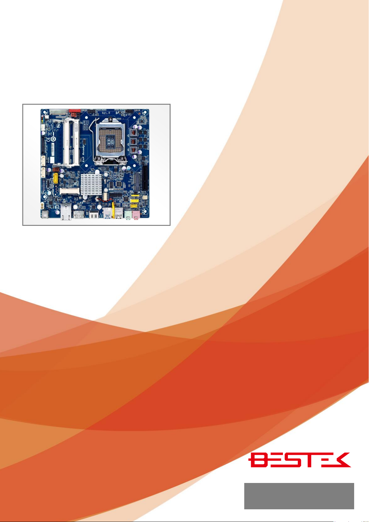
Embedded Board
BNX-I81
Always at the forefront of innovation
User Manual
2
This publication contains information that is protected by copyright. No part of it may be reproduced in any
form or by any means or used to make any transformation adaptation without the prior written permission
from the copyright holders.
This publication is provided for informational purposes only. The manufacturer makes no representations or
warranties with respect to the contents or use of this manual and specifically disclaims any express or implied
warranties of merchantability or fitness for any particular purpose. The user will assume the entire risk of the
use or the results of the use of this document. Further, the manufacturer reserves the right to revise this
publication and make changes to its contents at any time, without obligation to notify any person or entity of
such revisions or changes.
© 2011. All Rights Reserved.
All trademarks and registered trademarks of products appearing in this manual are the properties of their
respective holders.
This equipment has been tested and found to comply with the limits for a Class A digital device, pursuant to
Part 15 of the FCC rules. These limits are designed to provide reasonable protection against harmful interference
when the equipment is operated in a residential installation. This equipment generates, uses, and can radiate
radio frequency energy and, if not installed and used in accordance with the instruction manual, may cause
harmful interference to radio communications. However, there is no guarantee that interference will not occur
in a particular installation. If this equipment does cause harmful interference to radio or television reception,
which can be determined by turning the equipment off and on, the user is encouraged to try to correct the
interference by one or more of the following measures:
Reorient or relocate the receiving antenna.
Increase the separation between the equipment and the receiver.
Connect the equipment into an outlet on a circuit different from that to which the receiver is connected.
Consult the dealer or an experienced radio TV technician for help.
Notice:
1. The changes or modifications not expressly approved by the party responsible for compliance could void
the user’s authority to operate the equipment.
2. Shielded interface cables must be used in order to comply with the emission limits.
Copyright
Trademarks
FCC and DOC Statement on Class A
3
1. Warranty does not cover damages or failures that are raised from misuse of the product, inability to use the
product, unauthorized replacement or alteration of components and product specifications.
2. The warranty is void if the product has been subject to physical abuse, improper installation, modification,
accidents or unauthorized repair of the product.
3. Unless otherwise instructed in this user’s manual, the user may not, under any circumstances, attempt to
perform service, adjustments or repairs on the product, whether in or out of warranty. It must be returned
to the purchase point, factory or authorized service agency for all such work.
4. We will not be liable for any indirect, special, incidental or consequential damages to the product that has
been modified or altered.
It is quite easy to inadvertently damage your PC, system board, components or devices even before installing
them in your system unit. Static electrical discharge can damage computer components without causing any
signs of physical damage. You must take extra care in handling them to ensure against electrostatic build-up.
1. To prevent electrostatic build-up, leave the system board in its anti-static bag until you are ready to install
it.
2. Wear an antistatic wrist strap.
3. Do all preparation work on a static-free surface.
4. Hold the device only by its edges. Be careful not to touch any of the components, contacts or connections.
5. Avoid touching the pins or contacts on all modules and connectors. Hold modules or connectors by their
ends.
Important:
Electrostatic discharge (ESD) can damage your processor, disk drive and other
components. Perform the upgrade instruction procedures described at an ESD
workstation only. If such a station is not available, you can provide some ESD protection
by wearing an antistatic wrist strap and attaching it to a metal part of the system chassis.
If a wrist strap is unavailable, establish and maintain contact with the system chassis
throughout any procedures requiring ESD protection.
Warranty
Static Electricity Precautions

4
To avoid damage to the system:
• Use the correct AC input voltage range.
To reduce the risk of electric shock:
• Unplug the power cord before removing the system chassis cover for installation or servicing. After installation
or servicing, cover the system chassis before plugging the power cord.
Battery:
• Danger of explosion if battery incorrectly replaced.
• Replace only with the same or equivalent type recommend by the manufacturer.
• Dispose of used batteries according to local ordinance.
Before using the system, prepare basic system components.
If the system comes as a barebone; that is, none of the key components, including processor, memory, and hard
drive has been pre-installed as part of your purchase, you will need to at least ensure a compatible counterpart
is located and installed.
You will also need a few external system peripherals intended for the use of the system, a common pool with
at least a keyboard, a mouse, and a monitor is thus suggested.
Safety Measures
Before Using the System

5
Table of Content
Copyright ....................................................................................................................................................................
2
Trademarks ....................................................................................................................................................................
2
FCC and DOC Statement On Class A.............................................................................................................................. 2
Warranty ........................................................................................................................................................................ 3
Static Electricity Precautions......................................................................................................................................... 3
Safety Measures ............................................................................................................................................................ 4
Before Using the System Board..................................................................................................................................... 4
Table of Content ............................................................................................................................................................ 5
Chapter 1 General Information
1.1 Main
Feature ........................................................................................................................................................... 7
1.2
Specifications .......................................................................................................................................................
8
1.3 Board Layout ..................................................................................................................................................... 9
Chapter 2 Jumper Setting
2.1 Before You Begin ..................................................................................................................................... 11
2.2
Precautions.........................................................................................................................................................
11
2.3 Setting
Jumpers..................................................................................................................................................
12
2.4 Back Panel Connectors....................................................................................................................................... 13
2.5 Location of Jumpers and Connectors.............................................................................................................. 14
2.6 Jumpers........................................................................................................................................................... 16
2.7 Internal Connectors ........................................................................................................................................ 17
Chapter 3 Operation
3.1 System Memory.............................................................................................................................................. 23
3.2 Installing
Memory......................................................................................................................................
23
3.3 Adding 19Vdc Power......................................................................................................................................... 24
3.4 Adding PCIe Card ............................................................................................................................................ 25
3.5 Install a PCI Express Mini Card in the Full-Mini Card Slot............................................................................... 26
Chapter 4 BIOS Setup
4.1 Entering Setup ................................................................................................................................................ 29
4.2 Getting Help.................................................................................................................................................... 29
4.3 Control Keys .................................................................................................................................................... 29
4.4 The Main Menu............................................................................................................................................... 30
4.5 The Advanced Menu........................................................................................................................................ 31
4.6 The Chipset Menu..................................................................................................................................................... 34
4.7 The Boot Menu................................................................................................................................................ 36
4.8 The Security Menu .......................................................................................................................................... 38
4.9 The Save & Exit Menu...................................................................................................................................... 39
Table of contents
Other BESTEK Motherboard manuals

BESTEK
BESTEK BNX-H81 User manual

BESTEK
BESTEK BNX-M67 User manual

BESTEK
BESTEK BNX-M87 User manual

BESTEK
BESTEK BNX-A77 User manual

BESTEK
BESTEK BNX-A110 User manual

BESTEK
BESTEK BNX-I61 User manual

BESTEK
BESTEK BNX-M67 User manual

BESTEK
BESTEK BNX-C206 User manual

BESTEK
BESTEK BNX-M81 User manual

BESTEK
BESTEK BNX-A61B User manual


