A Keep the engine, gearbox
and surrounding area clean,
including the area immediately
below the engine
B DRIVES - Power Take Off
Areas
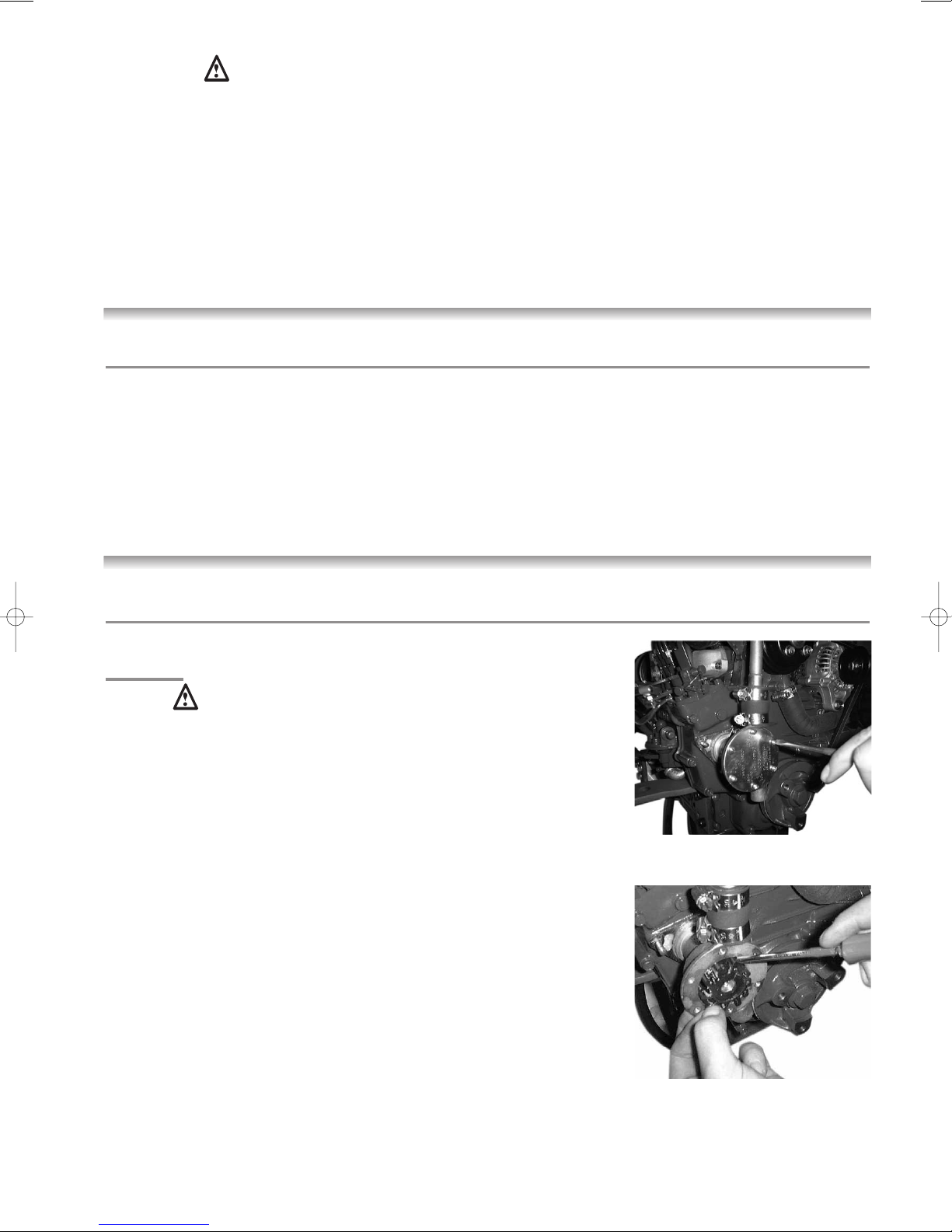
i) Gearbox Output Flange
The purpose of a marine diesel
propulsion engine is to provide
motive power to propel a vessel.
Accordingly the gearbox output
shaft rotates at between 280 and
2400 rev/min. This flange is
designed to be coupled to a
propeller shaft by the installer
and steps must be taken to
ensure adequate guarding.
ii) Forward End Drive
Engines are supplied with
unguarded vee belt drives to
power the fresh water pump and
battery charging alternator. The
installer must ensure that it is not
possible for injury to occur by
allowing accessibility to this area
of the engine. The three pulleys
run at high speed and can cause
injury if personnel or clothing
come in contact with the belts or
pulleys, when the engine is
running.
iii) Power Take Off Shaft
(Engine Mounted Option)
Shaft extensions are available as
an option and rotate at between
850 and 3600 rev/min. If
contact is made with this shaft
when the engine is running,
injury can occur.
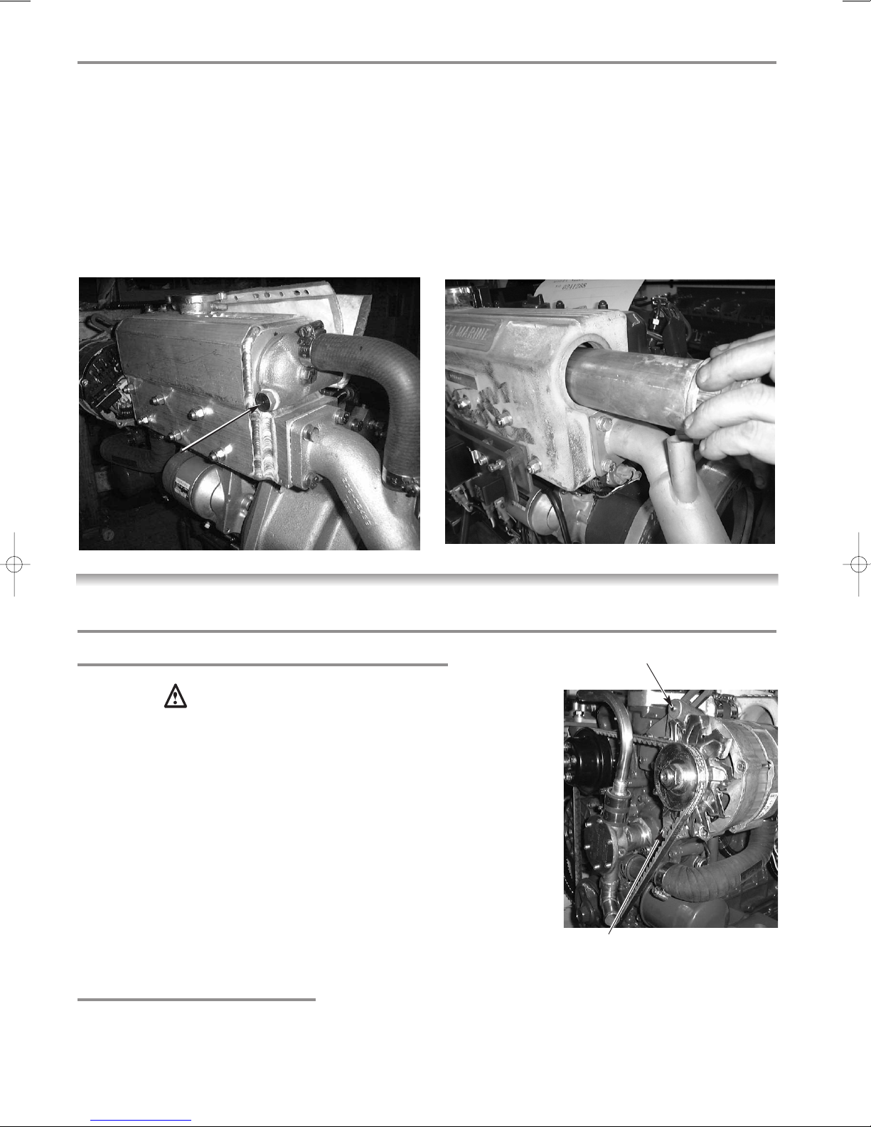
C EXHAUST OUTLET
Diesel marine propulsion engines
emit exhaust gases at very high
temperatures - around 400-
500°C. Engines are supplied with
either wet exhaust outlet (water
injection bend) or dry outlet (dry
exhaust stub) - see option list. At
the outlet next to the heat
exchanger/header tank, the
exhaust outlet can become very
hot and if touched, can injure.
This must be lagged or avoided by
ensuring adequate guarding. It is
the responsibility of the installer to
lag the exhaust system if a dry
system is used. Exhaust gases
are harmful if ingested, the
installer must therefore ensure that
exhaust lines are lead overboard
and that leakage in the vessel
does not occur.
D FUEL
i) Fuel Lines
Diesel engines are equipped with
high pressure fuel injection
pumps, if leakages occur, or if
pipes fracture, fuel at a high
pressure can harm personnel.
Skin must be thoroughly cleaned
in the event of contact with diesel
fuel.
ii) Fuel Supply Connections
Engines are supplied with 8 mm
compression fittings. The
installer must ensure that when
connections are made, they are
clean and free of leaks.
E OIL
The Beta propulsion is supplied
with 2 dipsticks, one for the
engine and one for the gearbox.
Ensure dipsticks are returned and
secure after checking, if not oil
leaks can cause infection when
touched. All oil must be
removed from the skin to prevent
infection.
F SCALDING
An engine running under load will
have a closed circuit fresh water
temperature of 85°to 95°C. The
pressure cap on the top of the
heat exchanger must not be
removed when the engine is
running. It can only be removed
when the engine is stopped and
has cooled down.
G
TRANSPORTATION/
LIFTING
Engines are supplied on
transportable pallets. Lifting eyes
on engines are used for lifting
engine and gearbox assembly
only, not the pallet and
associated kit.
GENERAL DECLARATION
This machinery is not intended to
be put into service until it has been
incorporated into or with other
machinery. It is the responsibility of
the purchaser/installer/owner, to
ensure that the machinery is
properly guarded and that all
necessary health and safety
requirements, in accordance with
the laws of the relevant country, are
met before it is put into service.
Signed:
J A Growcoot, C.E.O,
Beta Marine Limited
NOTE: Recreational Craft
Where applicable, the
purchaser/installer/owner and operator
must be responsible for making sure
that the Recreational Craft Directive
94/25/EC is complied with.
SAFETY PRECAUTIONS!