BETCO BPS28 Product manual

1
E89001P
BPS28
28” Battery Powered
Sweeper
1001 Brown Avenue • Toledo, Ohio 43607-0127
Customer Service: 888-GO-BETCO • Fax: 800-445-5056 • Technical Service: 877-856-5954 • www.betco.com
Operator and Parts
Manual

2
TABLE OF CONTENTS
GENERAL INFORMATION AND KEY ....................................3
1.1 SAFETY WARNING........................................................3
1.2 MACHINE REGISTRATION SHEET.................................4
1.3 SERIAL NUMBER AND CE MARKING............................4
1.4 TECHNICAL FEATURES AND SPECIFICATIONS.............4
1.5 FOREWORD ..................................................................5
1.6 MACHINE APPLICATION ...............................................5
1.7 UNPACKING THE MACHINE..........................................5
2.1 PREPARING THE MACHINE FOR OPERATION ..............5
2.2 PREPARING THE BATTERY FOR OPERATION ...............6
3.1 CONTROLS ...................................................................6
4.1 STARTING.....................................................................6
4.2 CORRECT OPERATION..................................................7
4.3 CLEANING THE WASTE BINS .......................................7
5.1 ROUTINE MAINTENANCE .............................................8
5.2 BATTERY MAINTENANCE .............................................8
5.2.1 BATTERY RECHARGE ................................................8
5.3 FILTER MAINTENANCE .................................................9
5.4 REPLACING AND ADJUSTING THE SIDE BRUSH .......10
5.5 REPLACING AND ADJUSTING THE CENTER BRUSH..10
5.6 REPLACING AND ADJUSTING THE BELTS..................11
5.7 REPLACING AND ADJUSTING THE FLAPS .................12
5.8 REPLACING AND POSITIONING THE CABLES............13
6.1 WIRING DIAGRAM......................................................14
6.2 TROUBLE SHOOTING .................................................15
6.3 SCRAPPING THE MACHINE........................................15
DIAGRAMS AND PARTS LISTINGS........................... 16 - 23
WARRANTY ......................................................................24

3
GENERAL INFORMATION – KEY
Indications such as RIGHT or LEFT, CLOCKWISE or COUNTER-CLOCKWISE used in this booklet relate to the
forward movements of the machine.
This symbol draws your attention top operations that could cause damage to the machine if
improperly executed.
This symbol draws your attention to operations that could cause injury to the operator if improperly
executed.
This symbol draws your attention to operations that must be read about very carefully.
Consult this manual carefully to gain confidence with your machine and learn how to use it more efficiently.
1.1 SAFETY WARNING
All the paragraphs in the following chapter may cause damage to people and/or objects if
improperly executed.
ALWAYS KEEPS THE MACHINE OUT OF THE REACH OF CHILDREN.
IMPORTANT NOTE:
Precautions to be taken before attempting to start the machine.
To facilitate transport,the side brush and the handlebar have not been assembled in their actual work position.
Therefore before using the machine, assemble them as shown in this handbook.
Do not use the machine to pick up (recover) liquid.
The machine must be used by authorized personnel only. Before cleaning or servicing the machine, always turn it
off.
As the machine is not provided with a parking brake or service brake, pay attention when you are using it on sloping
surfaces.
Do not leave the machine unattended on sloping surfaces.
The machine must be used only bY qualified and authorized personnel.
For this purpose, NEVER:
– use the machine to transport people;
– touch the moving parts of the machine;
– remove the machine’s guards when it is running;
– do not leave the operating machine unattended.
Always wear clothing suiting the kind of work you are carrying out.
If you are working in a particularly dusty environment (for instance; cement factories, sawmills, marble processing
factories), it is recommended that you wear:
– a mask
– protective goggles
– gloves
!
NOTE
!

4
Do not use a jet of water to wash the machine.
The machine must not be used for the recovery of toxic or hazardous substances.
The machine can only work in presence of light.
NEVER LEAVE the machine with the key in the dashboard unattended.
In case the machine is being used in a place where there is a danger for falling little objects, a helmet must be
worn by the operator.
Do not use the machine to sweep up cables, straps, wire, or similar material. Do not use the machine near cables,
wire, or similar material.
IMPORTANT: The manufacturer cannot be held responsible for damage in the event that the machine is used for
purposes other than those it was designed for.
The machine must never be tampered with for any reason whatsoever; in this event, the manufacturer will accept
no responsibility for improper use or damage to the machine.
1.2 MACHINE REGISTRATION SHEET
Model: BPS-28
Serial number: ______________________________ Date of manufacture:_______________
Commissioned on: _________________________ Commissioned by: _________________
1.3 SERIAL NUMBER AND CE MARKING
Always ensure that the machine is provided with a name plate
giving the serial number and CE marking. If not, advise your
dealer immediately.
1.4 TECHNICAL FEATURES AND SPECIFICATIONS
Maximum width with side brush . . . . . .810 mm
Maximum length with side brush . . . . . .1160 mm
Maximum height with side brush . . . . . .1000 mm
Actual cleaning width – main brush . . . .520 mm
Weight . . . . . . . . . . . . . . . . . . . . . . . . .68 kg
Weight of empty battery . . . . . . . . . . . .12.8 kg
Waste bin capacity . . . . . . . . . . . . . . . .32 lt.
Working life . . . . . . . . . . . . . . . . . . . . .3.5 h.
Filtering surface . . . . . . . . . . . . . . . . . .1.25 m∆
Productivity . . . . . . . . . . . . . . . . . . . . .2500m∆/h
Installed power . . . . . . . . . . . . . . . . . . .360W/28A
Battery type . . . . . . . . . . . . . . . . . . . . .12V 105A
Noise level . . . . . . . . . . . . . . . . . . . . . .68 dBA
Vibrations . . . . . . . . . . . . . . . . . . . . . . .2.5 m/Sec∆
SERIAL
NUMBER

5
1.5 FOREWORD
The purpose of this manual is to inform the operator of the basic rules, safety rules and criteria which must be
observed when using, adjusting and maintaining the machine. The machine has been developed and has been
developed and manufactured to ensure excellent performance and the utmost comfort and ease of operation in a
variety of working conditions. Before delivery, the machine has been checked at our factory and by our dealer to
make sure it is handed over to you in perfect working order: To maintain the machine in this condition and ensure
problem-free operation, it is essential to follow the routine maintenance instructions given in this handbook.
1.6 MACHINE APPLICATION
The machine, composed of a brush and a suction system, is to be used EXCLUSIVELY to clean dry surfaces. Any
other use could be cause of damage to people or things and is therefore PROHIBITED.
1.7 UNPACKING THE MACHINE
Unpack the machine with the utmost care; avoid carrying out any operation that that could damage it. Once it has
been unpacked, check whether it is damaged. If you notice that it is not in correct working order, DO NOT use it
and inform your dealer. For packaging and transport purposes, some parts and accessories are supplied
disconnected from the machine. To assemble them,carefully follow the instructions given in the relevant sections.
Contents of package:
1Machine
1Side brush
1Instructions and spare parts manual.
2Ignition keys
1Declaration of conformity
1 Warranty slip
1Handle's fixing key
If one of the above mentioned parts is missing, please inform your dealer right away.
Take care to keep the packaging materials (bags, cartons pallets, hooks, etc) out of the reach of
children.
For security during transport, the ignition keys and Handle's fixing key have been fixed to the handle.
2.1 PREPARING THE MACHINE FOR OPERATION
2.1.1 MOUNTING THE SIDE BRUSH
- Switch the brush lift lever to OFF.
- Remove the screw from the side brush drive shaft.
- Fit the brush on the shaft.
- Screw on the screw and washer.
2.1.2 MOUNTING THE HANDLEBAR (FIG. 2A)
Locate the handle at the right height, by using one of the fixing holes (Pos.1
or Pos.2). Fix the handle to the frame by means of 2 screws “A.”
!
NOTE
Fig. 2A

6
2.2 PREPARING THE BATTERY
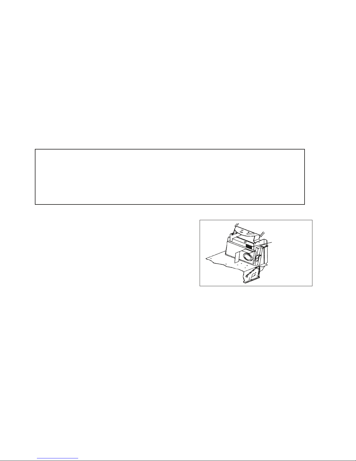
The battery must be prepared before it is mounted on the machine. This simple precaution will prevent
the machine from being damaged by the electrolytic liquid of the battery. Always prepare the battery
in a sufficiently ventilated environment. Do not smoke or use flames during this operation (see the
section on battery maintenance). Once the battery has been charged, make sure the electrolytic liquid
containers are stored in a safe place AWAY FROM CHILDREN.
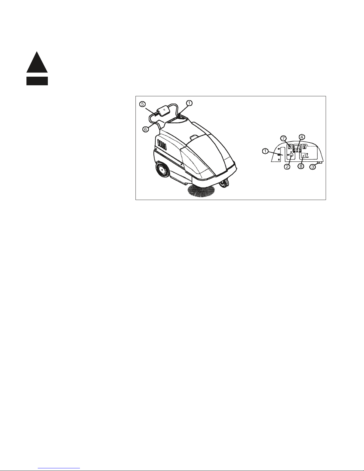
3.1 CONTROLS
1. Side brush control lever: Switch
the lever to ON and the side brush
will move to work position and
start spinning. To stop the brush,
switch the lever to OFF.
2. Key switch: This switch starts
and stops all the machine’s
functions.
3. Battery charger socket:By
plugging a battery charger in this
socket you will recharge the
battery.
4. Charge indicator light: This light indicates the state of the battery during operation.
5. Traction lever: By pressing this lever, the machine will start moving forwards.
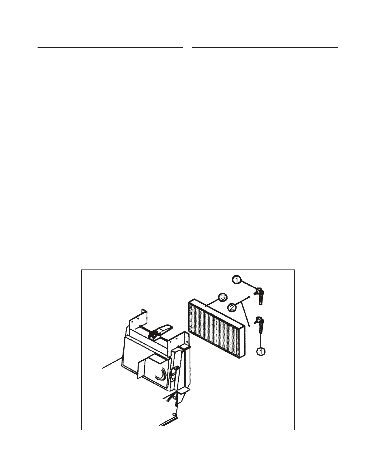
6. Filter shaker lever: This lever operates the filter shaker to clean the filter (see the section on filter
maintenance).
7. Mains led
8. Suction switch
4.1 STARTING
ATTENTION! The machine must be used by authorized personnel only. DO NOT leave the machine UNATTENDED
when it is running. Do not use the machine to soak up liquid. Take out the key before leaving the machine. KEEP
THE MACHINE OUT OF THE REACH OF CHILDREN.
To start the machine, carry out the following operations:
- Make sure the side brush (#1, Fig. 3) is OFF.
- Turn the switch (#2, Fig. 3) ON. Wait 10 seconds before the machine sets off.
- Before the machine sets working, check the indicator (#4, Fig. 3) to assess whether the battery is fully charged.
If it is not, proceed to recharge it.
- Pull the traction lever (#5, Fig. 3) to start cleaning.
If necessary, operate lever (#1, Fig. 3) by turning it ON, to start the side brush. If you have been using the side
brush, at the end of your work remember to turn it OFF. Switch off the machine and remove the key from the control
panel. An automatic device will prevent you from using the machine beyond a certain battery charge limit. When
this limit is reached, the machine will stop and the battery must be recharged.
!
NOTE
Fig. 3

7
4.2 CORRECT OPERATION
After you have become familiar with the operations required to start the machine, you can actually start using the
sweeper. To obtain the best results, it is always wise to take a few precautions. These will help you to get the best
from your machine and reduce damage to a minimum.
In particular:
-Do not use the machine to clean up wires, ropes or straps or pick up water and other liquids.
- When using the machine on light but bulky material (sheets of paper, leaves,etc.), raise the front part of the
machine by pressing down the handlebar so that the machine can tackle the rubbish.
-Operate the filter shaker at the end of your work (see the "Panel Filter"section").
-Make sure the center brush is correctly regulated (see the section on adjusting the centre brush).
4.3 CLEANING THE WASTE BINS
Before carrying out this operation, make sure all parts are off.
(*) ATTENTION: WASTES MUST BE DISPOSED OF STRICTLY IN ACCORDANCE WITH THE LAW.
4.3.1 FRONT BIN/DIRT HOPPER
Lift the hood.
Lift and turn the two bin locks.
Grasp the handle and remove the bin by pulling it upwards.
Empty the bin (*).
To put the bin back in place:
Put the bin back in the machine from the top.
Turn and lower the two locks.
4.3.2 REAR BIN/BACK DRAWER
Lift and turn the two bin locks.
Grasp the handle and pull the bin out of the machine.
Empty the bin (*).
To put the bin back in place:
Fit the bin back into the machine.
Turn and press the two locks.

8
5.1 ROUTINE MAINTENANCE
ALL ROUTINE MAINTENANCE AND SPECIAL MAINTENANCE MUST BE CARRIED OUT BY COMPETENT
PERSONNEL OR BY AN AUTHORIZED SERVICE CENTER .ALWAYS USE ORIGINAL SPARE PARTS.
ATTENTION: ALL MAINTENANCE OPERATIONS MUST BE CARRIED OUT WITH THE MACHINE OFF.
5.2 BATTERY MAINTENANCE
The battery must be kept clean and dry. Keep the terminals and poles clean. Every 10 hours, remove the caps and
check the electrolyte level. If necessary, top-off with distilled water.
The battery should be serviced in a properly ventilated area. During this operation, do not expose the battery to
open flames and do not smoke.
5.2.1 BATTERY RECHARGE
When the machine is off:
Remove the caps from the battery cells.
Top up with distilled water.
Plug in a battery charger (#3, Fig. 3) bearing up .
The life of the battery will depend on its routine maintenance and on its discharge level. Do not allow the battery
charge to drop below the limit signalled by indicator lights (#4, Fig.3). At the max. discharge level, the machine
stops and needs to be recharged in order to resume working.
CHARGE INDICATOR LIGHTS
GREEN LIGHT: The battery is charged.
YELLOW LIGHT: The battery is running out;recharge as soon as possible:
RED LIGHT: The battery has run out. DO NOT operate the machine.
CARBON BRUSH FOR ELECTRIC MOTOR:
Always try to replace these brushes before they reach 1000 hours of work.
!
NOTE
!
NOTE
CHECK
Check the battery liquid
The belts for slackening
The tightness of nuts and screws
The brushes for wear
The gaskets for wear and leakage
If all the functions are in working order
X X
X
X
X
X
X X

9
5.3 FILTER MAINTENANCE
CLEANING THE FILTER
The filter is one of the machine main components. It is essential for the best results from your machine. If you notice
that dust forms when the machine is at work, check the filter.
The filter is cleaned as follows:
A. Press and release the lever of the appropriate filter shaker, (#6, Fig. 3). The lever operates a rod that will unclog
the filter. Repeat this operation 5 or 6 times.
B. Apart from the filter shaker, it is advisable every now and again to remove the machine’s filter and clean it out
with a blast of air or a vacuum cleaner.
For this purpose,the filter is removed as follows:
- Remove the rear bin/back drawer.
- Lift the blocking handle (#1, Fig. 4).
- Rotate the handle, in order to remove the filter
- Remove the filter (#3, Fig. 4) while holding up the filter shaker rod.
- To remount the filter (#3, Fig. 4) carry out the operation in reverse order.
- ATTENTION: The filter features an arrow that shows you the direction in which it should be fitted.
DUSTY ENVIRONMENTS: If you are using the machine in a particularly dusty environment (cement factories,
sawmills, marble processing factories),it is wise to use the filter shaker more frequently.
REPLACING THE FILTER
Every 200 hours of work, the filter must be replaced. Follow the operations listed in point B.
After the filter has been remounted, make sure the gasket and filter are dust tight.
WASTES MUST BE DISPOSED OF IN ACCORDANCE TO THE LAW.
Fig. 4

10
5.4 REPLACING AND ADJUSTING THE SIDE BRUSH
REPLACING
After lifting the front part of the machine, replace the side brush by loosening the brush fixing screw and removing
the brush. Replace the brush and secure the new one in place with the screw and its washer.
ADJUSTING
The side brush is adjusted by loosening screws and using the slots to position the brush at the required height.
Once you have positioned it, tighten the two screws.
5.5 REPLACING AND ADJUSTING THE MAIN BRUSH
REPLACING
To replace the main brush, remove the front bin and loosen the four fixing screws to remove the brush.
When mounting a new brush, pay attention to the direction in which the brush will spin: it must direct dirt toward
the center of the machine.
ADJUSTING
To adjust the main brush, lift the top bonnet, loosen the lock nut (#2, Fig. 5) and turn adjusting handle (#1, Fig. 5)
in the direction required (counterclockwise to increase pressure). By pulling up the handle, the brush will turn idle.
This will allow you to position the brush in a place where it will not prevent the top bonnet from closing.
Fig. 5

11
5.6 REPLACING AND ADJUSTING THE BELTS
To prepare the machine for belt replacement, carry out the following operations:
-Remove the top bonnet and the front bin.
-After removing the right wheel, loosen the screws that secure the bumper and right side guard in place and
remove the latter.
With the machine dismantled in such a manner, you can replace the damaged belt.
5.6.1 REPLACING THE DRIVE BELT
-Remove belt (#1, Fig. 6) from the grooves of pulley.
-Position belt on pulley
5.6.1 REPLACING THE SIDE BRUSH BELT
-Remove belt (#7, Fig. 6) from pulley (#6, Fig. 6). Loosen fixing pin (#8, Fig. 6) and let the hooks of side arm
(#9, Fig. 6) come out of the idle toothed ring.
-Remove belt (#7, Fig. 6) from side arm (#9, Fig. 6).
-Replace the belt.
-Hook side arm (#9, Fig. 6) to the idle toothed ring.
-Tighten pin (#8, Fig. 6).
-Place belt (#7, Fig. 6) on pulley (#6, Fig. 6).
Fig. 6A
Fig. 6B

12
5.7 REPLACING THE FLAPS
5.7.1 OUTER SIDE FLAPS
To replace the side flaps (#1, Fig. 7), remove the rear wheels and the relevant side guards. Loosen the screws that
secure the flaps to frame (#2, Fig. 7) and replace the old flaps with new ones.
5.7.2 INNER SIDE FLAPS
To replace the inner side flaps (#5, Fig. 7), lift the front part of the machine and loosen screws (#6, Fig. 7) that
secure the flaps to the frame. Replace the old flaps with new ones.
5.7.3 CENTER FLAPS
- Remove the rear wheels and the relevant side guards.
- Remove the rear door.
- Loosen the two two flap fixing pins (#3, Fig. 7), located on the sides of the frame. Grasp flap (#4, Fig. 7) and pull
it outward.
Remounting
- Fit the flaps in the same direction in which they are removed.
- Insert the two references in their holes.
- Tighten the two fixing pins and
Fig. 7

13
5.8 REPLACING THE TRACTION CABLE
5.8.1 REMOVE THE TRACTION CABLE AS FOLLOWS:
- Open the upper hood of the machine.
- Lift the security dowel located on the cable fixing pin.
- Open the traction handle casing.
- Pull the cable out of the fixing pin and remove the adjusting screw mounted on the handle.
- Press the handle and pull the cable out of its sheath.
To remount the cable:
- Fit one end of the cable into the adjustment screw of the handle (i.e. the end without the blocking ball).
- Insert the cable into its sheath.
- Hook the blocking ball to the handle.
- Slot the cable through the turned adjustment screw secured to the machine frame and and then through the fixing
pin.
- Tighten the security dowel.
The position of the cable is adjusted by acting on the two adjustment screws.
5.8.2 REPLACING THE SIDE BRUSH LIFTING CABLE
To replace the side brush lifting cable, proceed as follows:
- Remove the upper hood and the front hopper of the machine.
- Remove the front bumper, the right wheel and the right hand side guard.
- Loosen the cable clamp.
- Loosen the security dowel on the fixing pin.
- Remove the handle from the support and open it up.
- Pull the cable out of the two sheaths.
To remount the cable:
- Put the cable inside the handle.
- Close up the handle and fix it to its support.
- Insert the cables into their sheaths.
- Secure one end of the cables in place with the clamp and the other end with the fixing pin.
The position of the cable is adjusted by acting on the two adjustment screws.

14
6.1 WIRING DIAGRAM

15
6.2 TROUBLESHOOTING
ydemeResuaCelbuorT
The main brush is not spinning.............The belt is broken........................................................Replace
The motoriduct has burnt out ......................................Replace
A wire is detached.......................................................Check
The side brush is not spinning..............The belt is broken........................................................Replace
The battery does not stay charged ......The liquid is insufficient ...............................................Top-off
The terminal is loose ...................................................Tighten
Dust comes out of the fan......................The filter is broken.......................................................Replace
The filter is in the wrong position ................................Position correctly
The gaskets are worn..................................................Replace
The brushes wear out too quickly ........The brushes are too low..............................................Adjust
Dust forms during operation..................The flaps are worn ......................................................Replace
Clogged filter ...............................................................Cleaning
The suction motor does not work .........The motor has burnt out..............................................Replace
The wire is disconnected.............................................Check
The machine does not come on ............The battery terminals are disconnected......................Check
The battery is discharged............................................Recharge
6.3 SCRAPPING THE MACHINE
In the event the machine must be scrapped, please remember that batteries are not common waste materials. They
must be disposed of in accordance with the relevant laws.
The machine is composed of different parts. Dismantle it and prepare the wastes for disposal or recycling in
accordance to their type.
DO NOT USE THE SCRAP PIECES AS SPARE PARTS.
KEEP SCRAPS OUT OF REACH OF CHILDREN.

16
DIAGRAM

17
PARTS LISTING
1 E89356 Upper Cover 1
2 E86585 Fixing Screw BPS 2
3 E89321 Nut M8 2
4 E89300 Hopper Locks 4
5 E89301 Handle Black 1
6 E89334 Washer 2
7 E87849 Screw BPS28 handle 2
8 E89302 Hopper Bin, Front Plastic 1
9 E86583 Bushing BPS 2
10 E89477 Front Cover BPS28 1
11 E89355 BPS Complete Rear Hopper 1
12 E86361 Dashboard for BPS28 1
13 E89513 Back Drawer Gasket for BPS28 1
14 E89399 Screw 6
15 E89078 Washer 8x17 4
16 E88547 Frame, BPS-28 1
17 E86540 Screw, M8x10 8
18 E89389 Right Side Casing 1
19 E89481 Left Side Casing 1
20 E89304 Front Casing 1
21 1370003 Foot 20x9 M6x18 2
22 E86701 Nut, M6 Zinc Hex 2
23 2300411 Right Hinge 1
24 2300412 Left Hinge 1
25 E86584 Bushing BPS 2
Item# Part # Description Qty. Item# Part # Description Qty.

18
DIAGRAM

19
PARTS LISTING
1 E89385 Sheathing 1
2 E89307 Traction Handle TK 530 1
3 E89425 Turned Adjuster #3 3
4 E89308 Lever Control Lateral B 1
5 E89309 Screw M6 x 16 1
6 1105303 Washer 6x12 3
7 1320031 Handwheel, 12x67 1
8 E89311 Ring Metal - Knurles 1
9 E89312 Sheath, Cable 1
10 E89063 Drive Cable BPS 28 1
11 E89427 Dowell #11 2
12 E89314 Screw Cable Fastening 2
13 E89078 Washer 8x17 7
14 E86853 Nyloc Hex Nut, M8 Zinc 3
15 E89315 Screw 8 x 25 3
16 2110025 Belt Tightening Lever 1
17 E89009 Spring 1
18 E89876 Screw 1
19 E89877 Roller, Belt 1
20 E89413 Bearing, 608 2RS 1
21 E89412 Inner Snap Ring 1
22 E89875 Spacer 1
23 2190011E Belt Tightener Bracket 1
24 E89175 Pin for rocker BPS28 2
25 E89176 Rocker bushing BPS28 2
26 2110017 Rocker 1
27 E87868 Self Locking Nut WS20/24 FS28/32 3
28 E89316 Screw 12 x 60 1
29 E89317 Non-Marking Caster 1
30 E89523 screw 6x20 BPS28 6
31 E89318 Screw M5 x 70 4
32 E89319 Nut M5 4
33 E89359 BPS Main Brush Assembly 1
34 E89383 Central brush shaft 1
35 E89199 Key 5-5-15 1
36 E87838 Brush Shaft Spacer BPS 28 2
37 E89081 Dowell 6x5 2
38 2260028 Bearing Support 2
39 E83277 Bearing, 6202 2RS 2
40 E89400 Outer Snap Ring 3
41 E89082 Outer Snap Ring 1
42 2230029 Brush Adjusting Fixing Pivot 1
43 E89079 Main Brush Adj. Bracket 1
44 2105001 Side Arm Felt Washer 2
45 E89482 Bearing, HK 1012 2
46 E86540 AS20 Screw M8x10 2
47 E89377 Spacer 1
48 E89321 Nut M8 2
49 E89322 Pulley, Brush Lateral 1
50 E89461 Gear Motor 1
51 E89334 Washer 1
52 E89387 Sheathing 1
53 E89386 Lift Cable 1
54 E87760 Pin 17x34 1
55 E89426 Clamp #55 1
56 E89324 Screw 8 x 22 1
57 E89076 Side brush lifting lever BPS 28 1
58 E89325 Washer 8 x 22 1
59 E89075 Ring for side brush BPS 28 1
60 E88498 Balls, Zinc 11/32" 6
61 E89084 Side Brush Toothed Ring BPS28 1
62 E89401 Key 3x3.7 1
63 2110012N Bushing 1
64 E86409 Bearing, 6005 2RS 2
65 E89085 Idle Toothed Ring BPS28 1
66 1105416 Outer Snap Ring 1
67 E89491 Traction Handle Casing 1
68 E86799 Spacer BPS28 2
69 E89326 Pulley, O27x15 Nylon 1
70 E89327 Belt, Dia. 8 x 1000 1
71 E89219 Washer 2
72 E89070 Side Brush Support 1
73 E86551 Side brush flange 1
74 E89328 Brush, Side 1
75 E89329 Pulley, O30x15 Nylon 1
76 E89330 Screw M6 x 10 3
77 E87788 Spacer 1
78 E89379 Bearing K1412 1
79 E87789 Spacer 1
80 E87790 Block Nut 1
81 E87935 Bushing 1
A. 2125100 Complete Brush Lifting Lever 1
B. E87770 Complete Movement Ring 1
C. E87771 Complete Idle Tooth Ring 1
D. 2310127 Complete Side Brush 1
E. E89424 Side Brush Sheathings and Cable (3-Piece Kit) 1
F. E89331 Carbon Brush 1
G. E87813 Bearing support BPS28 1
H. 2310291 Complete Pulley 1
I. 2310292 Complete Pulley 1
Item# Part # Description Qty. Item# Part # Description Qty.

20
DIAGRAM
Other manuals for BPS28
1
Table of contents
Popular Blower manuals by other brands

Broan
Broan NuTone 336 instruction manual

Nilfisk-Advance
Nilfisk-Advance CR 1000 Specifications

Tuchel
Tuchel PROFI 660 operating manual

Grizzly
Grizzly ALS 4032 Lion Translation of the original instructions for use

Geen Works
Geen Works 24132 owner's manual

Ebmpapst
Ebmpapst R4E225-AI01-09 operating instructions