EDRO DynaWash DW Series Guide

EDRO Dy n a Wa s h ®T h r e e P o c k e T W a s h e r - e xTracTors
1
INSTALLATION — OPERATION
PARTS MANUAL
THREE POCKET END-LOADING WASHER-EXTRACTORS
RIGID – SOFT MOUNT – PASSTHRU
Technical specications are based on the latest information available
at the time of printing and are subject to change without notice.
Manufactured in accordance to Canadian Standards Association general requirements.
The EDRO Corporation
37 Commerce Street - P.O. Box 308 • East Berlin, CT 06023-0308 USA
Tel. (860) 828-0311 • Fax (860) 828-5984 • Web www.edrocorp.com
Models: DW100, DW150, DW200, DW300 & DW400
Series: DW; DW_SM; DW_PT; DW_PTSM
DW Range:
End-Loading; Rigid Mount
DW_SM Range:
End-Loading; Soft Mount
DW_PTSM Range:
Barrier Type; Soft Mount
DW_PT Range:
Barrier Type; Rigid Mount
Date: Feb, 2016
Part No: MANC-1002 - Revision 6

EDRO Dy n a Wa s h ®T h r e e P o c k e T W a s h e r - e xTracTors
2

EDRO Dy n a Wa s h ®T h r e e P o c k e T W a s h e r - e xTracTors
3
The EDRO Corporation, from here on known as the Seller, warrants all EDRO DynaWash® washer extractors
shipped by it to be free from defects in material and workmanship for a period of eighteen (18) months from the date
of shipment from the Seller’s factory or two-thousand two-hundred operating hours whichever occurs rst, provided:
(a) the machine is used by the original Buyer, (b) it is given normal and proper usage, (c) all electrical and mechani-
cal connections are made in accordance with Seller’s specications, (d) proper installation and start up procedures
are employed by qualied personnel, (e) machine is not altered in any way, shape, or form from it’s original factory
specications, and (f) warranty card is completed and returned to Seller prior to warranty expiration.
Consumable and normal wear items, such as control switches, regulators, solenoids, gaskets, glass, and plastic are
not covered under this warranty. All labor charges incurred during any warranty activity are the sole responsibility
of the Buyer.
Notice of any warranty claim must be presented to the Seller immediately upon Buyer’s discovery of the defect. The
right of inspection must be given to the Seller while the product is in the claimed defective condition, and operation
of the product must be suspended until written clearance is issued for continued operation.
Upon receipt of a warranty claim notice, the Seller will proceed without unreasonable delay to remedy any defect
found to exist under the terms of warranty. During the warranty period, parts found to be defective after the Seller’s
inspection, will, at the Seller’s option, be repaired or replaced with new or factory rebuilt parts free of charge, except
that of freight charges, custom charges, or other associated fees involved with the returning of the defective compo-
nent to the Seller, and shipment of the replacement component will be the responsibility of the Buyer.
Vendor Supplied Items : Vendor supplied items shall be warranted in accordance with the available warranty, if any,
provided to the EDRO Corporation, by the vendor. Claims relating to vendor supplied items will be dealt with on a
case-by-case basis.
Five (5) year pro-rated warranty on shell, cylinder and frame. For a period of ve years, from the date of shipment,
EDRO DynaWash® shells, cylinders and frames are guaranteed not to develop any structural fractures to the
material due to workmanship.
There are no warranties which extend beyond the description and the warranties contained herein. The warranties
expressed herein are in lieu of any other warranties, expressed or implied. Any implied warranty of merchantability
and implied warranty of tness for a particular purpose are hereby excluded. The Buyer’s remedy is limited to, and
the Seller’s liability shall not exceed either, (1) repair or replacement of the defective part of the product or, at the
Seller’s option (2) return of the product and refund of the purchase price. Such remedy shall be the Buyer’s entire
and only remedy.
FAILURE TO COMPLETE AND RETURN WARRANTY REGISTRATION FORM WILL NULLIFY WARRANTY
Battleship Quality
NEW MACHINE LIMITED WARRANTY

EDRO Dy n a Wa s h ®T h r e e P o c k e T W a s h e r - e xTracTors
4
TABLE OF CONTENTS
SECTION 1 Page
Safety 8
Key to Symbols 10
Operator Safety 11
Machine Location 12
Input and Output Services and Requirements 12
Water Pressure 12
Steam Heating (Optional) 12
Electric Heating (Optional) 12
Compressed Air 12
Drainage System 12
Grounding 12
Electrical Overload 12
Misuse 13
Safe Operating Environment 13
End-User Responsibility for Environment Conditions 13
Ambient Temperature 13
Humidity 13
Ventilation 13
Elevation 14
Detergent Chemicals 14
Water Damage 14
SECTION 2
Installation 15
Rigid Mount Models (DW & DW_PT) 15
DynaMount Soft Mount Models (DW_SM & DW_PTSM) 15
PassThru Models (DW_PT & DW_PTSM 16
Foundation 16
Foundation Diagram (Plan View) 17
Grouting 19
Standard Plumbing Connections 19
Pneumatic Connections 19
Standard Electrical Connections 20
Service Connections 21
Plumbing 21
Electrical 21
DynaMount Soft Mount Models (DW_SM & DW_PTSM) 21
Hold Down Bolts 21
Air Pressure Safety Switch 21
Vibration Switch 21
Warranty Registration 21
Installation, On-Site Testing and Operational Checkout Form 22
SECTION 3
Theory of Operation 23
Design and Construction 24
DynOzone - DynaWash®Ozone System 25
Programming - DynOzone 25

EDRO Dy n a Wa s h ®T h r e e P o c k e T W a s h e r - e xTracTors
5
SECTION 3 (con’t)
Theory of Operation - DynOzone 25
System Monitoring During Operation 26
DynOzone - DynaWash®Ozone System Maintenance 27
PowerCell 27
Pump 27
Tubing 27
Fittings 27
Ballast 27
Options 27
Heating: Steam / Electric 27
Extra Drain & Extra Water Inlet (Water Reuse System) 28
Automatic Positioning 28
Safety Features 28
Automatic Braking on Power Failure 28
Positioning Interlock - Cylinder Jog 28
Door Lock 28
Emergency Stop 28
Vibration Switch 29
Customer Service 29
SECTION 4
Machine Operation 30
Before Operation 30
Loading 31
Automatic Operation 31
SECTION 5
Machine Conguration 33
Motor Setup 34
Water Level Setup 34
Ozone/Signal Setup 34
Timers Setup 35
Miscellaneous Congurable Parameters 35
Language Setup 36
Programming 36
Wash/Rinse Step 38
Drain Step 39
Extract Step 40
Operation 42
AutoStart 43
Wash Screen 44
Drain Screen 45
Extract Screen 45
Program Complete 45
Alarms and Warnings 46
Reports 47
Alarms 48
Counters 48
Program History 49

EDRO Dy n a Wa s h ®T h r e e P o c k e T W a s h e r - e xTracTors
6
SECTION 5 (con’t)
Technical Information 50
Onscreen Control Manual 50
Debug Screens 51
Settings 52
Control Information 52
Time & Date Settings 52
Screen Calibration & Brightness/Contrast 52
Password Management 53
Copy Program 54
Clear Program Names 54
Transfer Programs 54
USB Utilities 55
Reset Factory Programs 55
Default Factory Programs 55
Reset Machine Defaults 55
SECTION 6
General Maintenance 56
Periodic Maintenance 56
2 Motor Drive Models Only 57
Inverter with Single Motor Drive Models Only 57
Periodic Maintenance Requirements 57
Lubrication Diagram 58
Maintaining the Clutch 59
Installation 59
To replace discs or repair clutch 59
Maintaining the Brake 60
Installation 60
Lubrication 60
Maintenance 60
Inverter with Single Motor Drive Models Only 60
Maintaining the Bearings 61
Lubrication 61
Removal 61
Installation 61
Solid Seals 62
Bearing Mounting Bolts 62
Torque Requirement 62
SECTION 7
Troubleshooting Guide 63
Introduction 63
DynaTrol 63
Preliminary Troubleshooting 63
General PLC Troubleshooting 64
Troubleshooting Procedures 65
PLC Input and Output Function Description 65
Troubleshooting Guide 66

EDRO Dy n a Wa s h ®T h r e e P o c k e T W a s h e r - e xTracTors
7
SECTION 8
PassThru Models Only 69
Operation 69
PassThru Control System - PushButton and Indicator Functions 69
Operating Instructions 70
Loading (Soiled or Loading) Operations 70
Unloading (Clean or Unload Side) Operations 71
SECTION 9
Parts Reference and Drawings 72
Control Dashboard Operation Lights and Switches 72
Soiled Room Control 72
Clean Room Control Operation Light and Switches PassThru Only 73
Drain Assembly 74
Bearing Assembly 76
Main Water and Automatic Supply Valves 78
Direct Steam Injection 79
Indirect Steam Injection 80
Main Door Assembly 82
Door Latch Assembly 83
Inner Door Assembly 84
Cylinder Assembly 85
Motor Assembly - PassThru Models Only (DW100PT) 86
Motor Assembly - PassThru Models Only (DW150 - DW200PT) 87
Motor Assembly - PassThru Models Only (DW300PT) 88
Motor Assembly - PassThru Models Only (DW400PT) 89
Transfer Shaft Assembly - PassThru Models Only 90
Drive Assembly 92
Brake Assemblies 93
Vibration Sensor 94
Vibration Switch 95
Pneumatic Assembly (Standard) 96
Pneumatic Assembly (Water Reuse System) 98
Automatic Positioning 100
DynaMount Suspension System 101
Variable Speed Motor Wiring 102
Extract Motor Connection 103
2-Motor, Three Speed Wiring 104
Electrical Panel Assembly - Non-PassThru Models Only 105
Electrical Panel Assembly - PassThru Models Only 108
Electrical Schematic Non-PassThru Models Only 110
Electrical Schematic PassThru Models Only 111
Installation, On-Site Testing and Operational Checkout Form 112

EDRO Dy n a Wa s h ®T h r e e P o c k e T W a s h e r - e xTracTors
8
Section 1
SAFETY
Anyone operating or servicing this machine must follow the safety rules in this manual.
Particular attention must be paid to the DANGER, WARNING, and CAUTION blocks, which
appear throughout the manual. The following warnings are general examples that apply to
these machines. Warnings specic to a particular installation or maintenance procedure will
appear in the manual with the discussion of that procedure.
DANGER
Identies a condition, which is not strictly
observed could result in injury to or death
to personnel.
WARNING
Identies an operating or maintenance
procedure, practice, statement, etc.,
which if not strictly observed could result
in injury to or death to personnel.
CAUTION
Identies an operating or maintenance
procedure, practice, condition, statement,
etc., which if not strictly observed could
result in damage to or destruction of
equipment or loss of effectiveness.
NOTE
Identies an essential operating or
maintenance procedure, precondition or
statement which are essential but not of
a known hazardous nature as indicated
by warnings and cautions.

EDRO Dy n a Wa s h ®T h r e e P o c k e T W a s h e r - e xTracTors
9
The following are general CAUTION, DANGER and WARNING notices to be familiar with when working
or servicing the machine.
CAUTION
Be careful around the open door, particularly when loading
from a level below the door. Impact with door edges can
cause personal injury.
WARNING
Dangerous voltages are present in the electrical control
box(s) and at the motor terminals. Only qualied personnel
familiar with electrical test procedures, test equipment, and
safety precautions should attempt adjustments and trou-
bleshooting. Disconnect power from the machine before
removing the control box cover, and before attempting any
service procedures.
DANGER
Death or serious injury can result if children become
trapped in the machine. Do not allow children to play on
or around this machine. Do not leave children unattended
while the machine door is open.
WARNING
This machine must be installed, adjusted, and serviced by
qualied electrical maintenance personnel familiar with the
construction and operation of this type of machinery. They
must also be familiar with the hazards involved. Failure to
observe this warning may result in personnel injury and/or
equipment damage, and may void the warranty.
CAUTION
Ensure that the machine is installed on a level oor of
sufcient strength and that the recommended clearance for
inspection and maintenance are provided. Never allow the
inspection and maintenance space to be blocked.
WARNING
Never touch internal or external steam pipes, connections,
or components. These surfaces can be extremely hot and
will cause severe burns. The steam must be turned off and
the pipe, connections, and components allowed to cool to
a safe temperature before the pipe can be touched.
EDRO Dy n a Wa s h ®T h r e e P o c k e T W a s h e r - e xTracTors
10
KEY TO SYMBOLS
The Lightning bolt within the triangle is a warning sign indicating the presence of dangerous
voltage.
The exclamation point within the triangle is a warning sign indicating important instructions
concerning the machine and possibly dangerous conditions.
This warning symbol indicates the presence of potentially dangerous drive mechanisms and
possibly dangerous pinch points within the machine. Moving mechanical parts can crush
and/or sever body parts. Guards should always be in place when the machine is in operation.
This warning symbol indicates the presence of possibly dangerous chemicals. Proper
precautions should be taken when handling corrosive or caustic materials.
This warning symbol indicates the presence of hot surfaces that could cause serious burns.
Steel and steam lines can become extremely hot and should not be touched.
Safety decals appear at crucial locations on the machine. Failure to maintain legible safety
decals could result in injury to the operator or service technician. To provide personal safety
and keep the machine in proper working order, follow all maintenance and safety procedures
presented in this manual. If questions regarding safety arise, contact the factory immediately.
Use factory-authorized spare parts to avoid safety hazards.
EDRO Dy n a Wa s h ®T h r e e P o c k e T W a s h e r - e xTracTors
11
OPERATOR SAFETY
To ensure the safety of the machine operators, the following maintenance checks must be
performed daily:
Prior to operating the machine, verify that all warning signs are present and legible. Missing or
illegible signs must be replaced immediately. Make certain that spares are available.
Check door interlock before starting operation of the machine. Attempt to start the machine
with the door open. The machine should not start with the door openand an alarm should sound.
If the door lock and interlock are not functioning properly, call a service technician.
Do not attempt to operate the machine if any of the following conditions are present:
a. The door does not remain securely locked during the entire cycle.
b. Excessively high water level is evident.
c. Machine is not connected to a properly grounded circuit.
DO NOT BYPASS ANY SAFETY DEVICES IN OR ON THE MACHINE.
WARNING
NEVER insert hands or objects into cylinder until it has
completely stopped. Doing so could result in serious injury.
WARNING
NEVER operate the machine with a bypassed or discon-
nected vibration switch or sensor. Operating the machine
with severe unbalanced loads could result in personal
injury and serious equipment damage.

EDRO Dy n a Wa s h ®T h r e e P o c k e T W a s h e r - e xTracTors
12
MACHINE LOCATION
Foundation: The concrete oor must be of sufcient strength and thickness to handle the oor
loads generated by the high extract speeds of the machine.
Service/Maintenance Space: Provide sufcient space to allow comfortable performance of
service procedures and routine preventative maintenance.
CAUTION
Replace all panels that are removed to perform service and
maintenance procedures. Do not operate the machine with
missing guards or with broken or missing parts. Do not
bypass any safety devices.
INPUT AND OUTPUT SERVICES AND REQUIREMENTS
Water Pressure: Best performance will be realized if water is provided at a pressure of 30-85
PSI (2.0-5.7 bar). Although the machine will function at a lower pressure, increased ll times
will occur. Water pressure higher than 100 PSI (6.7 bar) may result in damage to machine
plumbing. Component failure(s) and personal injury could result.
Steam Heating (Optional): Best performance will be realized if steam is provided at a pressure
of 30-80 PSI (2.0-5.4 bar). Steam pressure higher than 125 PSI (8.5 bar) may result in
damage to the machine and may cause personal injury. For machines equipped with optional
steam heating, (either direct or indirect), install piping in accordance with approved commercial
steam practices. Failure to install the supplied steam lter may void the warranty.
Electric Heating (Optional): For best performance, size the power source to the power rating of
the heating element and in accordance with local codes. A qualied electrician must determine
the amount of power supplied.
Compressed Air: Air source should provide pressure between 80-100 PSI (5.4-6.7 bar).
Drainage System: Provide drain troughs large enough to accommodate the total number of
gallons that could be dumped if all machines on the site drained at the same time from the
highest attainable level. Troughs should be covered to support light foot trafc.
Grounding: For personal safety and for proper operation, the machine must be grounded in
accordance with State and Local Codes. The ground connection must be to a proven earth
ground, not to conduit or water pipes.
Electrical Overload: Do not use fuses in place of a circuit breaker. Each machine should be
connected to a separate circuit breaker, with proper suppression devices for the machine. The
circuit breaker must be an inverse time type. An easy-access disconnect switch should also
be provided. These components must conform to the latest National Electric Code (NEC) and
State and Local Codes.

EDRO Dy n a Wa s h ®T h r e e P o c k e T W a s h e r - e xTracTors
13
WARNING
Ensure that a ground wire from a proven earth ground is
connected to the ground lug near the input power block
on this machine. Without proper grounding, personal injury
from electric shock could occur and machine malfunctions
may be evident.
MISUSE
Never wash petroleum-soaked rags in machine. This could result in an explosion.
Never wash mechanical parts or automotive parts in machine. This could result in serious
damage to the cylinder.
Never allow children to play on or around machine. Death or serious injury can result if
children become trapped in machine. Do not leave children unattended while machine door is
open. These cautions apply to animals as well.
Always disconnect power and water supplies before a service technician performs any service
procedure. Where applicable, steam supply should also be disconnected before service is
performed.
SAFE OPERATING ENVIRONMENT
Safe operation requires an appropriate operating environment for both the operator and the
machine. If questions regarding safety arise, contact EDRO immediately.
END-USER RESPONSIBILITY FOR ENVIRONMENT CONDITIONS
Ambient Temperature: Temperatures above 120º F (50º C) will result in more frequent motor
overheating and in some cases, malfunction or premature damage to solid state components.
Special cooling devices may be necessary. Increases and decreases in temperature affect
water pressure switches. Every 25º F (10º C) change in temperature will have a 1% effect on
the water level. Water in the machine will freeze at temperatures of 32º F (0º C) or below.
Humidity: Relative humidity above 90% may cause the machine’s electronics or motors to
malfunction or may trip the ground fault interrupter. A corrosion problem may occur on some
metal components in the machine. If the relative humidity is below 30%, belts and rubber
hoses may eventually develop dry rot. This condition can result in hose leaks, which may
cause safety hazards external to the machine in conjunction with adjacent electrical equipment.
Ventilation: The need for make-up air openings for the washer-extractor and other laundry
room accessories such as dryers, ironers, water heaters, etc. must be evaluated periodically.
Louvers, screens, or other separating devices may reduce the available air opening signicantly.
EDRO Dy n a Wa s h ®T h r e e P o c k e T W a s h e r - e xTracTors
14
Elevation: If the machine is to be operated at elevations of over 3,280 feet (1,000 meters)
above sea level, pay special attention to water levels and electronic settings (particularly
temperature) or desired results may not be achieved.
Detergent Chemicals: Keep all steel surfaces free of chemical residues. Damage to any
part of the machine caused by corrosion resulting from the use of concentrated chemicals
will impede machine performance and is specically excluded from warranty.
DANGER
Do not place volatile or ammable uids in any machine.
Do not clean the machine with volatile or ammable
uids such as acetone, lacquer, thinners, enamel reducers,
carbon tetrachloride, gasoline, benzene, etc. Doing so
could result in serious personal injury and/or damage to
the machine.
Water Damage: Do not spray the machine with water. Short circuiting and serious damage
may result. Immediately repair all seepage due to worn or damaged gaskets, etc.

EDRO Dy n a Wa s h ®T h r e e P o c k e T W a s h e r - e xTracTors
15
Section 2
It is the responsibility of the Installer to check and complete the
following items upon installation of the machine.
The installation procedure of your DynaWash® washer-extractor should not take more than one
day to complete. Except for re-connecting certain parts disconnected in shipping, no internal
assembly or wiring is necessary. By reading these instructions carefully and following the
recommended procedures, you will not only save time, but should avoid many unnecessary
complications and possible future problems.
INSTALLATION
For installing DynaWash® Rigid Mount Models (DW100, DW150, DW200, DW300, DW400, and
DW100PT, DW150PT, DW200PT) the ground oor thickness must be at least 12” (ref. page 17),
and must be constructed of the equivalent of 5,000 PSI re-enforced concrete. For upper oor
installations, check with a structural engineer to verify the capability of the oor to support the
machine’s static operating weight. Static operating weight is equal to the machine weight, a full
load of laundry and 100% full water. Before positioning the machine, be sure to have adequate
oor area to achieve a level foundation. Existing oors should be lled in if necessary to obtain
the area needed for a proper installation. DynaWash® rigid mount models with down drain are
designed to straddle a drain trough. Models with drain to rear option are designed to be piped
to a sewer drain. It is required that all factory supplied mounting holes in the base footings of
the machine be used to anchor the machine to the oor.
RIGID MOUNT MODELS (DW & DW_PT)
For installing DynaWash® with DynaMount Soft Mount option (DW100SM, DW150SM,
DW200SM, DW300SM, DW400SM, and DW100PTSM, DW200PTSM, DW300PTSM DW-
400PTSM), the oor thickness must be constructed of the equivalent of 5,000 PSI re-enforced
concrete and able to support the machine’s static operating weight. For upper oor installations,
check with structural engineer to verify the capability of the oor to support the machine’s static
operating weight. Static operating weight is equal to the machine weight, a full load of laundry
and 100% full water. Even though the deection of vibration is less than 5%, before position-
ing the machine, be sure to have adequate oor area to achieve a level foundation. This is
important so that the washer can maintain a stable and level operating environment and not
put undue stress on any components of the suspension system. To achieve this condition, the
existing oor should be lled in if necessary to obtain the area needed for a proper installation.
We require the existing four (4) holes in the machine’s base be used for anchoring the base of
the machine to the oor.
The shock absorbers and reverse loaded coil springs on DynaMount units are pre-adjusted at
the factory, however, nal adjustments maybe necessary and should be made as follows:
DYNAMOUNT SOFT MOUNT MODELS (DW_SM & DW_PTSM)

EDRO Dy n a Wa s h ®T h r e e P o c k e T W a s h e r - e xTracTors
16
Tighten shock nuts snug at upper and lower locations. DO NOT CRUSH THE RUBBER
BUSHINGS!
Main spring shafts should have two (2) full threads extending beyond lower locks nuts to
ensure proper locking action.
To achieve the required operating clearance or if leveling is required, rst determine which
spring assembly is out of level, then loosen the locking nut and either tighten or loosen the
adjusting nut located on the threaded rod at the top of the main spring shaft assembly.
Perform this operation in intervals of two (2) full turns at a time to compress or release the
reverse loaded coil spring. Repeat as necessary. Once level, tighten the lock nut. For
optimum performance, DynaWash® washer-extractors should be level left to right, as well as
front to back. Minimum distance from the bottom of the front and rear plate to the top of the
base plate is 1-1⁄4 ” (3.175 cm).
•
•
•
The PassThru option of DynaWash® machines, DW_PT and DW_PTSM, differs from the other
models by its construction allowing the machine to be loaded from one side and unloaded from
the other. The operation and the performance of these machines are identical with the standard
end loading DynaWash® units. PassThru units require the installation of the clean side seal.
The superstructure of the clean side seal goes between clean side of unit and barrier wall. The
clean side plate of the machine has bolts studded to it to assist in assembly of the barrier
material from the machine to the barrier wall.
PASSTHRU MODELS (DW_PT & DW_PTSM)
It is vitally necessary to provide a proper foundation for DynaWash® machines. Anchor the
machine to the oor by either pouring a new foundation in accordance with factory specications
or install on existing oor. In either case, the foundation should be constructed of 5,000 PSI
re-enforced concrete. For installations on upper oors, check with a structural engineer to verify
the capability of the oor to support the machine’s static weight and forces once in operation.
For best machine performance, it is recommended that DynaWash® straddle a drain trough,
unless the drain to rear option is ordered in which case the machine should be piped directly to
a sewer drain. The drain trough should have a capacity to sustain the maximum amount of
water for all machines at the site if all washers were to simultaneously drain from their high
water level.
Minimum foundation requirements can be found on the following charts. For reference, the
minimum foundation requirement for DynaMount Soft Mount models (DW_SM & DW_PTSM)
is ability of oor to support the static weight of a fully loaded machine taking into account a 5%
variance for vibration deection. Variations may be made to suit a specic installation as long
as minimum and/or maximum requirements are met.
FOUNDATION
EDRO Dy n a Wa s h ®T h r e e P o c k e T W a s h e r - e xTracTors
17
MINIMUM FOUNDATION REQUIREMENT
DW100 DW150 DW200 DW300 DW400
12” 16” 16” 18” 20”
DW100 DW150 DW200 DW300 DW400
18” 18” 20” 24” 24”
MAXIMUM TRENCH WIDTH
MAXIMUM TRENCH WIDTH
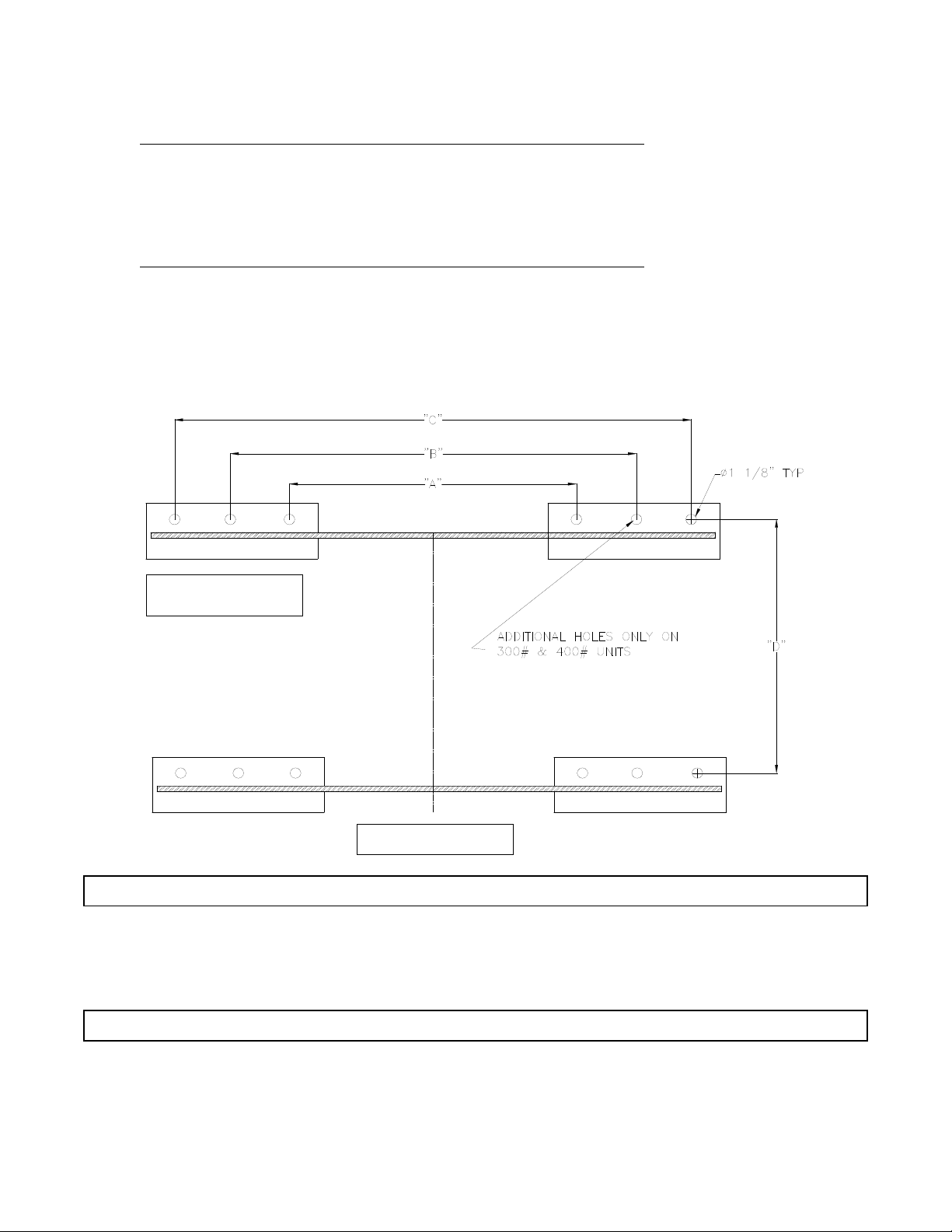
DW (End-Loading Rigid Mount) & DW_PT (PassThru Rigid Mount)
Plan View of Machine
Footprint
Machine Front
DW
DW_PT
Dimension 100 150 200 300 400
A23 30 30 35 1⁄243
BN/A N/A N/A 47 1⁄255
C47 54 54 59 1⁄267
D31 32 5⁄839 5⁄849 1⁄449 1⁄4
Dimension 100 150 200 300 400
A35 1⁄249 49 N/A N/A
BN/A N/A N/A N/A N/A
C59 1⁄273 73 N/A N/A
D27 7⁄829 36 1⁄8N/A N/A

EDRO Dy n a Wa s h ®T h r e e P o c k e T W a s h e r - e xTracTors
18
DW_SM (End-Loading Soft Mount) & DW_PTSM (PassThru Soft Mount)
Machine Front
DW_SM
Dimension 100 150 200 300 400
A82 88 90 92 100
B38 41 5⁄848 3⁄857 57
DW_PTSM
Dimension 100 150 200 300 400
A92 99 101 102 3⁄8108
B38 40 5⁄847 3⁄857 55
NOTE
Drawings reect standard production models. Options
such as Electrical Right (ER) will effect foundation layout.
NOTE
All dimensions are in inches.
NOTE
To avoid alignment errors install foundation bolts after
machine placement.

EDRO Dy n a Wa s h ®T h r e e P o c k e T W a s h e r - e xTracTors
19
It is very important to understand that proper grouting of DynaWash® machines will result in
best performance. Correct grouting will assure perfect alignment of the machine with the oor.
GROUTING
View of Bolting and
Grouting Requirement
RIGID MOUNT MODELS (DW & DW_PT):
First, make the foundation level and at. Next, pour grout in area that the base of the machine
will be located. Then lower the machine on the grouted area evenly. Check level front to back
and side to side. Pull down high side(s) using foundation bolts. Allow grout to harden. Install
all at washers and lock washers and tighten all nuts. After service connections are made run a
cycle and recheck that all nuts are tight. Make periodically checks as follows:
1. Daily for one (1) week.
2. Weekly for one (1) month.
3. Set up periodic inspection. (Section 6).
DYNAMOUNT SOFT MOUNT MODELS (DW_SM & DW_PTSM):
Install Soft Mount models as in paragraph above. Before loading and running the rst cycle
adjust the suspension system to the following measurements. Bottom of front plate to base
must be 1 1⁄4” and front plate must be level side to side. Bottom of rear plate to base must be 1
1⁄8” and rear plate must be level side to side. When machine is fully loaded with water it should
be level front to back.
STANDARD PLUMBING CONNECTIONS
PNEUMATIC CONNECTIONS
All DynaWash® machines require a single compressed air source of three-quarter (1⁄4”) NPT at a
minimum of 80 PSI (5.4 bar).
DW100 DW150 DW200 DW300 DW400
Inlet Valve 11⁄4” 2” 2” 2” 2”
Drain Valve 4” 6” 6” 8” 8”
NOTE
Reference installation drawings for proper length of J-bolt
and concrete depth per model.

EDRO Dy n a Wa s h ®T h r e e P o c k e T W a s h e r - e xTracTors
20
STANDARD ELECTRICAL CONNECTIONS
DW100 DW150 DW200 DW300 DW400
Wire Size #6 AWG #6 AWG #6 AWG #2 AWG #2 AWG
Circuit Breaker 30 AMP 50 AMP 50 AMP 100 AMP 100 AMP
208 - 240 volts / 3 phase / 60 cycle:
440 - 480 volts / 3 phase / 60 cycle:
DW100 DW150 DW200 DW300 DW400
Wire Size #12 AWG #10 AWG #10 AWG #6 AWG #6 AWG
Circuit Breaker 20 AMP 25 AMP 25 AMP 50 AMP 50 AMP
380 - 415 volts / 3 phase / 50 cycle:
DW100 DW150 DW200 DW300 DW400
Wire Size #10 AWG #8 AWG #8 AWG #6 AWG #6 AWG
Circuit Breaker 25 AMP 30 AMP 30 AMP 60 AMP 60 AMP
NOTE
Options such as Water Reuse System and Electric Heating
Element will require larger wire sizes and must be
determined at site by a qualied electrician. Contact
Factory for Electrical Connections not listed.
2 MOTOR - 3 SPEED DRIVE
DW100 DW150 DW200 DW300 DW400
Wire Size #6 AWG #6 AWG #6 AWG #2 AWG #2 AWG
Circuit Breaker 30 AMP 30 AMP 50 AMP 80 AMP 100 AMP
230 volt / 3 phase / 60 cycle:
460 volt / 3 phase / 60 cycle:
DW100 DW150 DW200 DW300 DW400
Wire Size #12 AWG #10 AWG #10 AWG #6 AWG #6 AWG
Circuit Breaker 20 AMP 20 AMP 25 AMP 40 AMP 50 AMP
SINGLE MOTOR
This manual suits for next models
20
Table of contents


