Beton Trowel RIDE ON BT900 2PFH User manual

Beton Trowel nv
Nijverheidsstraat 11
1840 Londerzeel/Belgium
Tel: +32 (0)52 315 350 - Tel: +32 (0)52 315 351
Fax: +32 (0)52 303 739
E-mail: info@betontrowel.com
BE 0821.249.312
www.betontrowel.com
BNP FORTIS:
ING:
BE81 0015 9813 5624
BE
-
GEBABEBB
BBRUBEBB
Pag.
1/35
INSTRUCTION MANUAL
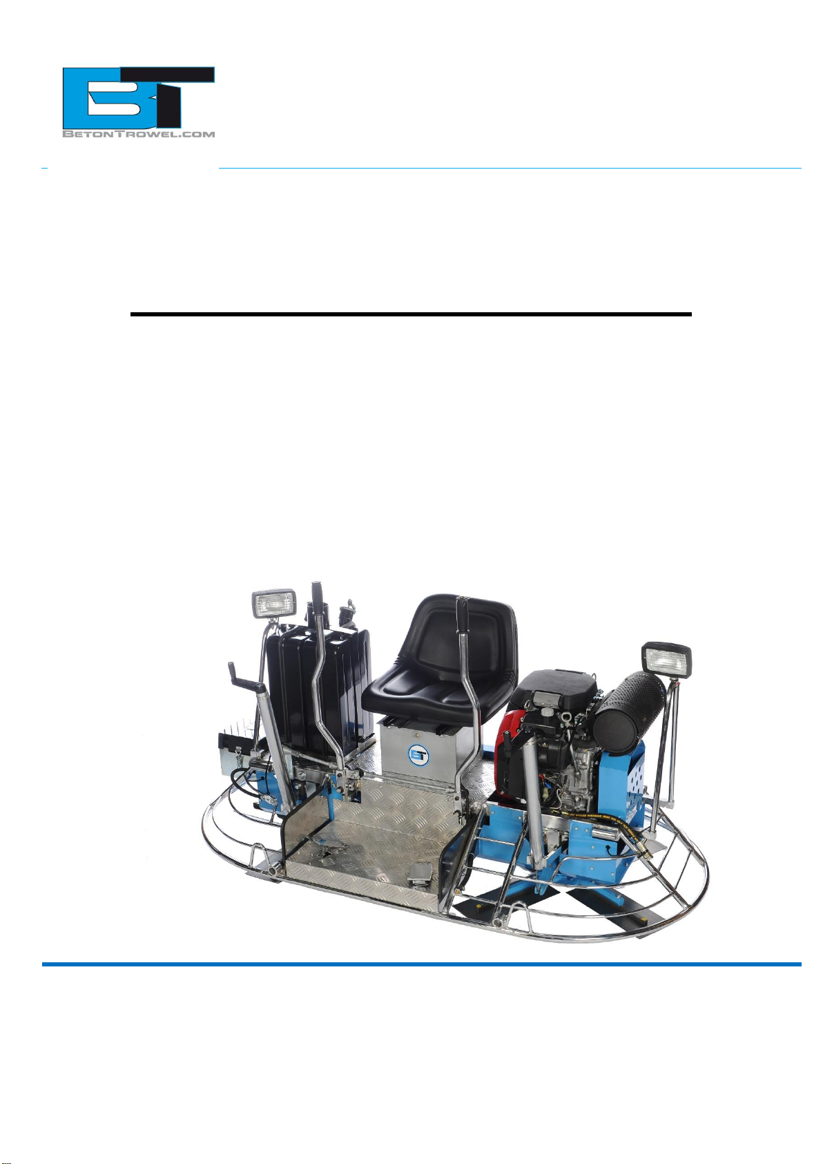
RIDE ON POWER TROWEL
–
BT900 2PFH Low rider
BT900H 2PFH Low rider

Beton Trowel nv
Nijverheidsstraat 11
1840 Londerzeel/Belgium
Tel: +32 (0)52 315 350 - Tel: +32 (0)52 315 351
Fax: +32 (0)52 303 739
E-mail: info@betontrowel.com
BE 0821.249.312
www.betontrowel.com
BNP FORTIS:
ING:
BE81 0015 9813 5624
BE
-
GEBABEBB
BBRUBEBB
Pag.
2/35
Use this guide along with the parts lists attached to locate and identify components of
your trowel. When ordering replacement parts, be sure to provide the model number
and serial number from the trowel.
Copyright
© Copyright 2011 by Beton Trowel.
Contact
BETON TROWEL
Nijverheidsstraat 11
1840 Londerzeel
BELGIUM
www.betontrowel.com

Beton Trowel nv
Nijverheidsstraat 11
1840 Londerzeel/Belgium
Tel: +32 (0)52 315 350 - Tel: +32 (0)52 315 351
Fax: +32 (0)52 303 739
E-mail: info@betontrowel.com
BE 0821.249.312
www.betontrowel.com
BNP FORTIS:
ING:
BE81 0015 9813 5624
BE
-
GEBABEBB
BBRUBEBB
Pag.
3/35
Foreword
Quality assurance / machine break in
The Beton Trowel Ride-on Trowel is the product of extensive engineering
development designed to give long life and unmatched performance. Once machines
are fully assembled, a run-in test is performed to ensure quality standards of the
highest level. A series of operational tests are conducted on concrete, incorporating a
phase of operations at 1/2 to 3/4 throttle and a final run phase at full throttle for a
minimum of 20 minutes.
You can help ensure that your Ride-on will perform at top levels by observing a
simple routing on first use. Consider that your new Ride-on Trowel is like a new car.
Just as you would break in a new car to the road or any new machine to the job, you
should start gradually and build up to full use. Learn what your machine can do and
how it will respond. Refer to the engine manufacturer’s manual for run-in times. Full
throttle and control may be used after this time period, as allowed by material. This
will serve to further break in the machine on your specific application, as well as
provide you with additional practice using the machine.
We thank you for the confidence you have placed in us by purchasing a Beton
Trowel Ride-on Trowel and wish you many years of satisfied use.

Beton Trowel nv
Nijverheidsstraat 11
1840 Londerzeel/Belgium
Tel: +32 (0)52 315 350 - Tel: +32 (0)52 315 351
Fax: +32 (0)52 303 739
E-mail: info@betontrowel.com
BE 0821.249.312
www.betontrowel.com
BNP FORTIS:
ING:
BE81 0015 9813 5624
BE
-
GEBABEBB
BBRUBEBB
Pag.
4/35
Table of contents
Foreword 3
Safety precautions 5
Assembly instructions 6
1 Battery –Shipped dry –No acid 6
2 Steering handle assembly 6
3 Pitch control Assembly 6
4 Seat Assembly 7
5 Transporter Assembly 7
Operating Instructions 8
1 Starting procedures –warm temperatures 8
2 Starting procedures –cold temperatures 8
3 To Stop engine 8
4 Steering 9
5 Float/Trowel pitch setting 10
6 Blade synchronization (specially modified units only) 10
7 Transporter Use 11
Trowel arm adjustment fixture 12
1 Adjustment Procedure 13
2 Trowel arm adjustment screw 14
Maintenance 15
1 Preventative maintenance and routine service plan 15
2 Lubrication 16
3 Maintenance plan 17
4 Service 19
Labels 20
Specifications 21
1 Technical data sheet 21
2 Parts 22

Beton Trowel nv
Nijverheidsstraat 11
1840 Londerzeel/Belgium
Tel: +32 (0)52 315 350 - Tel: +32 (0)52 315 351
Fax: +32 (0)52 303 739
E-mail: info@betontrowel.com
BE 0821.249.312
www.betontrowel.com
BNP FORTIS:
ING:
BE81 0015 9813 5624
BE
-
GEBABEBB
BBRUBEBB
Pag.
5/35
Safety Precautions
Always keep unauthorized, inexperienced, untrained people away from this
machine.
Rotating and moving parts will cause injury if contacted. Make sure guards are
in place. Keep hands and feet away from moving parts.
Fuel the machine only when the engine is stopped, using all necessary safety
precautions.
The engine must always be stopped before attempting any repair or
adjustments. Ignition key should be off.
Danger: Never operate the machine in an explosive atmosphere,
near combustible materials or where ventilation does not clear
exhaust fumes. Repair fuel leaks immediately.
Refer to your engine owner’s manual for more safety instructions.
Be careful not to come in contact with the muffler when the engine is hot,
serious burns may result!
Always operate the machine in a seated position to maintain machine balance.
The transporter is designed for moving the unit around the job site only. It is
not to be used for towing the Ride-On unit off-site.
When starting the trowel, do not exceed the ¼ throttle position as
recommended. A higher setting could cause the centrifugal clutch to engage,
turning the trowel blades.
Be careful with the trowel around stub pipes or other obstructions on the floor.
Should the machine catch, or hit such an obstruction, serious damage may
result to the machine, or operator may be thrown from the machine.
Excess surface water may result in sudden loss of control of steering.
Disconnect battery before attempting any electrical maintenance.
Ensure that the electrical dead-man switch, located on the right hand steering
lever is operating. Placing your right hand on the steering lever will engage the
safety switch. Removing your hand from the Lever will disengage the safety
switch and stop the engine. The engine will not start unless the safety switch
is depressed. This safety feature must be used as designed

Beton Trowel nv
Nijverheidsstraat 11
1840 Londerzeel/Belgium
Tel: +32 (0)52 315 350 - Tel: +32 (0)52 315 351
Fax: +32 (0)52 303 739
E-mail: info@betontrowel.com
BE 0821.249.312
www.betontrowel.com
BNP FORTIS:
ING:
BE81 0015 9813 5624
BE
-
GEBABEBB
BBRUBEBB
Pag.
6/35
Assembly Instructions
1 Battery –Shipped dry –No acid
Connect and secure the battery cables before attempting starting procedures.
2 Steering handle assembly
The steering handles are shipped ready to connect.
Position the handles over the handle sleeves so that the set-screws (2 per handle)
are lined up with the tapped holes on the sleeves. Tighten the set-screws and test
the mobility of the handles.
3 Pitch control Assembly
Bolt pitch control tube (C) to pitch
control bracket (D) with bolts provided.
Put cable end (E) through yoke arm
(F) and secure with nylon insert
locknut (G). For proper cable
adjustment, turn crank (A) counter-
clockwise to the stop position. Tighten
nut (G) until all slack in the cable is
removed. If more than 2 or 3 threads
show through the nut, it should be
turned back and the guide screw (B)
moved to the next lower hole. Tension
in the cable should then be readjusted.
After adjusting tension, turn hand
crank full clockwise (ABOUT 24
TURNS) and check for clearance
between the yoke arm (F) and the gear
box at point (H). There should be
enough space to pass a business card
through but not more than 1/8 inch.

Beton Trowel nv
Nijverheidsstraat 11
1840 Londerzeel/Belgium
Tel: +32 (0)52 315 350 - Tel: +32 (0)52 315 351
Fax: +32 (0)52 303 739
E-mail: info@betontrowel.com
BE 0821.249.312
www.betontrowel.com
BNP FORTIS:
ING:
BE81 0015 9813 5624
BE
-
GEBABEBB
BBRUBEBB
Pag.
7/35
4 Seat Assembly
Remove protective wrapping from seat. The seat is now ready to secure to the frame
using included washers and hex nuts. If the seat adjuster is ordered, the slider bars
must be positioned between the seat and the frame using included screws to secure
the seat to the sliders, and then securing the sliders to the frame as indicated above.
5 Transporter Assembly
The components of the transporter (handle, frame, wheels, and parts bag) are
shipped separately, requiring some assembly. Extend the handle outside the frame.
Slide the handle along the frame cross-bar to align the hole on the handle with the
hole on the “U” frame. Insert the large hitch pin (part #12487) through the hole to
secure the handle to the “U” frame. Position one of the wheels on the axle and
secure in place by inserting pin (part #10315) into the hole on the end of the axle.
Repeat procedure for the other wheel.
CAUTION: The transporter is designed to be used on the job site only.
Do not use the transporter to tow the machine off-site.

Beton Trowel nv
Nijverheidsstraat 11
1840 Londerzeel/Belgium
Tel: +32 (0)52 315 350 - Tel: +32 (0)52 315 351
Fax: +32 (0)52 303 739
E-mail: info@betontrowel.com
BE 0821.249.312
www.betontrowel.com
BNP FORTIS:
ING:
BE81 0015 9813 5624
BE
-
GEBABEBB
BBRUBEBB
Pag.
8/35
Operating Instructions
1 Starting procedures –warm temperatures
Prior to starting the trowel, check the engine and gearbox oil levels. Be sure
the fuel tank is full.
Fuel is not shipped with the unit. Before attempting to start, fill the fuel tank.
Check engine and gearbox oil levels. WARRANTY IS VOID IF RUN
WITHOUT OIL. Fill tank with safety approved fuel containers. DO NOT MIX
OIL WITH FUEL.
Maintain contact with the dead-man safety switch. Engine will disengage and
stop if safety switch is released. Do not tape, tie-down, or otherwise attempt to
bypass safety device.
Turn ignition key all the way. Allow engine to warm up before proceeding with
full trowel operation.
2 Starting procedures –cold temperatures
Follow same procedure as above but allow for a longer warm up period 3-5 min. (In
cold weather oil is much heavier to move. Extra time is required to heat the oil.)
3 To Stop engine
Bring throttle to low idle, wait a few seconds.
Remove left foot from dead-man safety switch.
Turn off ignition key.

Beton Trowel nv
Nijverheidsstraat 11
1840 Londerzeel/Belgium
Tel: +32 (0)52 315 350 - Tel: +32 (0)52 315 351
Fax: +32 (0)52 303 739
E-mail: info@betontrowel.com
BE 0821.249.312
www.betontrowel.com
BNP FORTIS:
ING:
BE81 0015 9813 5624
BE
-
GEBABEBB
BBRUBEBB
Pag.
9/35
4 Steering
Guiding the machine on the
slab is quite simple but does
require some familiarity
before actually working
with the machine. The
controls respond as shown in
figure 2a below. Test the
machine on a finished
section of the floor, with the
blades in a flat position,
and the engine at a low
revolution to gain the
necessary feel for the
steering.
For straight line movement, move both handles as one in the direction you wish to
travel. Move the handles in opposite directions to produce rotation on the machines
axis. Left handle forward, right handle backward for clockwise rotation. Left handle
backward, right handle forward, for counter-clockwise rotation. Sideways
direction is achieved by sideways movement of the right handle in the required
direction of travel.
WARNING: SERIOUS INJURY OR PROPERTY DAMAGE MAY
RESULT DUE TO TEMPORARY LOSS OF CONTROL IF OPERATED
WITH EXCESS LIQUID ON THE CONCRETE SURFACE.

Beton Trowel nv
Nijverheidsstraat 11
1840 Londerzeel/Belgium
Tel: +32 (0)52 315 350 - Tel: +32 (0)52 315 351
Fax: +32 (0)52 303 739
E-mail: info@betontrowel.com
BE 0821.249.312
www.betontrowel.com
BNP FORTIS:
ING:
BE81 0015 9813 5624
BE
-
GEBABEBB
BBRUBEBB
Pag.
10/35
5 Float/Trowel pitch setting
Once you are familiar with the steering functions on a flat floor, you are ready to
combine the steering with float/trowel pitch settings to produce the finish
you require. The pitch adjustment feature of the Beton Trowel RIDE-ON TROWEL
permits quick and accurate pitch changes of the finishing/float blades, without having
to stop the machine. Turning the adjustment crank-handle at the end of the pitch
control tubes enables you to change the pitch whenever necessary to allow for
varying conditions over the slap surface.
Each spider plate is adjusted independently. The pitch setting will affect the steering
of your unit. Experiment with the settings as you test drive so you will know what to
expect. CAUTION: Do not let the machine stand in one spot on the soft
concrete; This may place unnecessary strain on the clutch to break it
free of the concrete. If the unit has been sitting for any length of time,
break it free from the concrete before attempting operation.
CAUTION: When finishing concrete above grade, erect a situation barrier along the
edge of the slab as a protective measure. The barrier must follow all applicable
codes and should be such that it will stop the trowel from riding over the edge of the
slab in case of loss of control.
6 Blade synchronization (specially modified units only)
To avoid blades hitting, make
sure spider plates are positioned
as shown with respect to each
other after performing any
maintenance.

Beton Trowel nv
Nijverheidsstraat 11
1840 Londerzeel/Belgium
Tel: +32 (0)52 315 350 - Tel: +32 (0)52 315 351
Fax: +32 (0)52 303 739
E-mail: info@betontrowel.com
BE 0821.249.312
www.betontrowel.com
BNP FORTIS:
ING:
BE81 0015 9813 5624
BE
-
GEBABEBB
BBRUBEBB
Pag.
11/35
7 Transporter Use
The transporter is designed to be used on the job site only. Do not use it
to tow the machine offsite.
The transporter has pick-up brackets located on the inside of the wheels which
should be positioned under the pick-up points on the frame. Before connection, the
handle will be pointing upwards at approximately a 45 degree angle. Pull the handle
down, engaging the transporter and secure the bracket and transporter to the
frame by locking the handle bracket in the frame lock by means of the hitch pin.
Using the handle as a lever, the ride-on may now be moved. To disconnect the
transporter, follow the above steps in reverse.

Beton Trowel nv
Nijverheidsstraat 11
1840 Londerzeel/Belgium
Tel: +32 (0)52 315 350 - Tel: +32 (0)52 315 351
Fax: +32 (0)52 303 739
E-mail: info@betontrowel.com
BE 0821.249.312
www.betontrowel.com
BNP FORTIS:
ING:
BE81 0015 9813 5624
BE
-
GEBABEBB
BBRUBEBB
Pag.
12/35
Trowel arm adjustment fixture
1) 10411 –Trowel arm
2) 10817 –Lift lever
3) 10808 –Jam nut
4) 10809 –Set screw
5) 10824 –Block top
6) 10507 –Bolt
7) 10816 –Jam nut
8) 10815 –Carriage bolt
9) 10832 –Adjustment bar
10) 10507 –Bolt
The trowel arm adjustment fixture (20801) is reversible. By rotating the arm clamping
fixture and the ring bolt, both left hand and right hand trowel arms may be
adjusted. Before attempting adjustment, determine whether the trowel arm is right
handed or left handed. When adjusting left hand trowel arms use the side of the
fixture marked “L”. When adjusting right hand trowels arms use the opposite side.
The adjustment bar will be set on “46” for the BT900 trowel arm.

Beton Trowel nv
Nijverheidsstraat 11
1840 Londerzeel/Belgium
Tel: +32 (0)52 315 350 - Tel: +32 (0)52 315 351
Fax: +32 (0)52 303 739
E-mail: info@betontrowel.com
BE 0821.249.312
www.betontrowel.com
BNP FORTIS:
ING:
BE81 0015 9813 5624
BE
-
GEBABEBB
BBRUBEBB
Pag.
13/35
1 Adjustment Procedure
Remove all trowel arm assemblies (1 & 2 arm and attached lift lever) from
suspected maladjusted spider plate.
Remove lift lever (2) from trowel arm (1) by first loosening jam nut (3) then
square head screw (4). If upon inspection (method left to discretion of
serviceman) any trowel arm (1) is found to be in a bent condition, it must either
be brought back to its original straight condition (method left to the
serviceman’s discretion) or replaced with new part.
Replace lift levers (2) on new or straightened arms (1) by reversing procedure
described above.
NOTE: IT IS IMPORTANT THAT WHEN TIGHTENING SQUARE
HEAD SETSCREW (4), IT SEATS ITSELF SECURELY INTO
DIMPLE MACHINED IN ARM.
Place trowel arm assembly (1 and 2) in fixture (5) with lift lever (2) butting up
against fixture. Secure in place with bolts (6).
Loosen locknut (7) and screw carriage bold (8) down to full depth allowable.
This will provide for ample clearance to swing adjustment bar (9) over head of
carriage bolt. Adjustment bar (9) is stamped for appropriate size of machine.
Swing appropriate side directly over carriage bolt (8) and secure in place with
bolt (10).
Adjust carriage bolt (8) upwards until contact is made with adjustment bar (9);
holding carriage bolt in position with one wrench, tighten locknut (7) to secure
in position with second wrench.
NOTE: IT IS VITALLY IMPORTANT TO ENSURE THAT ONCE
THE CARRIAGE BOLT IS ADJUSTED TO THE CORRECT
HEIGHT, IT DOES NOT MOVE BEFORE, OR DURING THE
TIGHTENING OF LOCKNUT.
This same procedure is to be followed with ALL arms from spider plate
assembly, and will ensure correct and exact adjustment.

Beton Trowel nv
Nijverheidsstraat 11
1840 Londerzeel/Belgium
Tel: +32 (0)52 315 350 - Tel: +32 (0)52 315 351
Fax: +32 (0)52 303 739
E-mail: info@betontrowel.com
BE 0821.249.312
www.betontrowel.com
BNP FORTIS:
ING:
BE81 0015 9813 5624
BE
-
GEBABEBB
BBRUBEBB
Pag.
14/35
2 Trowel arm adjustment screw
When assembling trowel blades to trowel arms, the adjustment screw should NEVER
protrude below the under-side surface to a trowel arm except when using for
emergency on-site adjustment to level trowel blades. If the adjustment screw is not
flush with the underside of the trowel arm, then this will cause the power trowel to
bounce and vibrate especially at high speed. This will also cause the trowel blades to
leave an uneven finish on the concrete due to the blades not being level to one
another. Make certain that the adjusting screw is held firmly in place while tightening
the bolt which secures the blade to the trowel arm.

Beton Trowel nv
Nijverheidsstraat 11
1840 Londerzeel/Belgium
Tel: +32 (0)52 315 350 - Tel: +32 (0)52 315 351
Fax: +32 (0)52 303 739
E-mail: info@betontrowel.com
BE 0821.249.312
www.betontrowel.com
BNP FORTIS:
ING:
BE81 0015 9813 5624
BE
-
GEBABEBB
BBRUBEBB
Pag.
15/35
Maintenance
1 Preventative maintenance and routine service plan
This trowel has been assembled with care and will provide years of service.
Preventative maintenance and routine service are essential to the long life of your
trowel. Your dealer is interested in your new machine and has the desire to help you
get the most value from it. After reading through this manual thoroughly, you will find
that you can do some of the regular maintenance yourself. However, when in need of
parts or major service, be sure to see Beton Trowel.
GENERAL
• Keep engine oil clean. Change according to engine manufacturer’s
specifications.
• Maintain the oil levels in the engine and gearbox assemblies. Change as
required.
• Use only clean fuel in the engine.
• Check for loose nuts and bolts on the trowel and tighten as necessary.
• Check “V” belts for wear, replace if worn.
• Grease all fittings daily. See diagram.
• Clean the unit after every use to prevent hardening of concrete residue. Hard
concrete is very difficult to remove, greatly increases weight and reduces
efficient subsequent operation of unit.
• Check clutch linings regularly for wear. Linings should be changed when 3/4
worn. Do not allow metal to metal contact as this will damage the clutch drum.
(New lining is 8mm.)
AIR CLEANER
Maintaining a clean engine will extend engine life. Keep air filter clean at all times.
Clean air filter using the recommended solvent. See engine manual for proper
cleaning procedure. Let the filter dry before reinstalling.
SPARK PLUG
Check and clean spark plugs regularly. A fouled, dirty spark plug causes hard
starting and poor engine performance. Set spark plug gap to recommended
clearance. Refer to engine manual.

Beton Trowel nv
Nijverheidsstraat 11
1840 Londerzeel/Belgium
Tel: +32 (0)52 315 350 - Tel: +32 (0)52 315 351
Fax: +32 (0)52 303 739
E-mail: info@betontrowel.com
BE 0821.249.312
www.betontrowel.com
BNP FORTIS:
ING:
BE81 0015 9813 5624
BE
-
GEBABEBB
BBRUBEBB
Pag.
16/35
BELT TENSIONING SPECIFICATIONS
NOTE: Belts may become slightly loose after the first few hours of
operation. It is important to retension the belts with the tool provided
and use the table given as reference.
2 Lubrication
ENGINE OIL
The long life and successful operation of any piece of machinery is dependent on
frequent and thorough lubrication.
Before using the trowel, always check your engine for oil. Use proper engine oil as
recommended in the engine manufacturer’s manual. Fill crankcase to levels as
recommended.
SPIDER PLATE
There are 8 (eight) grease fittings on the spider plates, 4 (four) on each must be
greased daily.
SPIDER PLATES MUST BE GREASED EVERY TIME MACHINE IS USED.
GEARBOX
Check the oil level sight plugs on both gearboxes daily to ensure the oil is half way
on the site glass. Top up with Agma 8 compounded gear oil only. Gearbox capacity
on the BT900 is 27oz./767ml.
TO CHANGE GEARBOX OIL
Place a pan beneath the drain plug to catch the oil. Remove the drain plug and the
filler plug from the gearbox. After the oil has drained completely, replace the drain
plug and tighten. Fill the gearbox through the filler plug with 27oz./767ml. of Agma 8
compounded gear oil. Replace the filler plug and tighten.
GREASE FITTINGS
There are 6 bearings in total. Grease all bearings and U-joints to ensure adequate
supply of lubricant. They are located above the gearboxes (2 per gearbox) and
2 located in the drive system. The U-joints are located in the drive system as well.

Beton Trowel nv
Nijverheidsstraat 11
1840 Londerzeel/Belgium
Tel: +32 (0)52 315 350 - Tel: +32 (0)52 315 351
Fax: +32 (0)52 303 739
E-mail: info@betontrowel.com
BE 0821.249.312
www.betontrowel.com
BNP FORTIS:
ING:
BE81 0015 9813 5624
BE
-
GEBABEBB
BBRUBEBB
Pag.
17/35
3 Maintenance plan

Beton Trowel nv
Nijverheidsstraat 11
1840 Londerzeel/Belgium
Tel: +32 (0)52 315 350 - Tel: +32 (0)52 315 351
Fax: +32 (0)52 303 739
E-mail: info@betontrowel.com
BE 0821.249.312
www.betontrowel.com
BNP FORTIS:
ING:
BE81 0015 9813 5624
BE
-
GEBABEBB
BBRUBEBB
Pag.
18/35

Beton Trowel nv
Nijverheidsstraat 11
1840 Londerzeel/Belgium
Tel: +32 (0)52 315 350 - Tel: +32 (0)52 315 351
Fax: +32 (0)52 303 739
E-mail: info@betontrowel.com
BE 0821.249.312
www.betontrowel.com
BNP FORTIS:
ING:
BE81 0015 9813 5624
BE
-
GEBABEBB
BBRUBEBB
Pag.
19/35
4 Service
Due to the nature and environment of use, power trowels are exposed to severe operating
conditions.
Some general maintenance guidelines will extend the useful life of your trowel.
The initial service for your power trowel should be performed after 25 hours of use, at
which time your mechanic (or authorized repair shop) should complete all of the
recommended checks in the schedule above.
Regular service according to the schedule above will prolong the life of the power
trowel and prevent expensive repairs.
Keeping your power trowel clean and free from concrete residue is the single most
important regular maintenance operation, over and above the checks in the service
schedule above, that can be performed.
Components such as oil seals, belts, drive line parts and bearings are prone to
premature wear from exposure to concrete residue. Using a spray-on release agent
on your power trowel before each use will make clean-up after use easy and extend
the time between replacement of most of the wearing components of the machine.
After each use your power trowel should be cleaned to remove any concrete residue
from the undercarriage and surrounding components. Use of a power washer will
make clean up quick and easy, especially if a release agent was applied prior to use.
In the Service Schedule above, items that should be checked, replaced or adjusted
are indicated by “o” in the appropriate column. Not all power trowel models include
the same features and options and as such not all service operations may have to be
performed. For ease of recording place a checkmark (√) through the “o” when the
item is complete. If an item is not required or not completed place an “x” through the
“o” in the box.
For all fuel-line powered trowels the governed speed of the engine is 2000 to 3600
rpm. See engine manufacturer’s manual for exact specifications. Care should be
used when making any adjustments to the power trowel not to change the governed
speed. Increasing the governed speed of the engine may lead to premature failure
and void the manufacturer’s warranty.
Failure to have your power trowel regularly serviced and properly maintained in
accordance with the manufacturer’s instructions will lead to premature failure and
void the warranty.

Beton Trowel nv
Nijverheidsstraat 11
1840 Londerzeel/Belgium
Tel: +32 (0)52 315 350 - Tel: +32 (0)52 315 351
Fax: +32 (0)52 303 739
E-mail: info@betontrowel.com
BE 0821.249.312
www.betontrowel.com
BNP FORTIS:
ING:
BE81 0015 9813 5624
BE
-
GEBABEBB
BBRUBEBB
Pag.
20/35
Labels
This manual suits for next models
1
Table of contents
Other Beton Trowel Trowel manuals
Popular Trowel manuals by other brands

Bartell
Bartell BXR830 Owner's manual and parts book

MQ Multiquip
MQ Multiquip JS36/30H55DE Series Operation and parts manual

Lievers
Lievers LTM600ER user manual

allen
allen HDX Series Operations & parts manual

MULTIQUIP
MULTIQUIP Whiteman series Operation manual

Dynapac
Dynapac BG49 Series Instructions and spare parts catalogue

Bartell
Bartell TS100 Instruction manual & parts book

Norton
Norton Clipper CT 901 ME operating instructions

MULTIQUIP
MULTIQUIP Whiteman JTN Operation and parts manual

Bartell
Bartell TS74 instruction manual

Schwamborn
Schwamborn BAS 1500E Translation of original operating manual

allen
allen Hydra-Drive Extreme Series Operation and parts manual