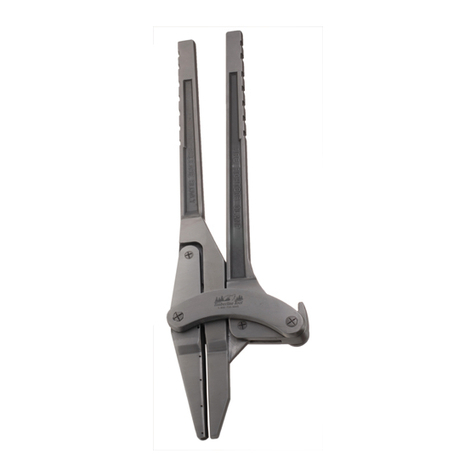
BEVELER Xpipe Specification sheet

Fixture Xpipe Beveler
for bevelling pipes and tubes
Order No. 25500
Instructions for use and maintenance
It is necessary to use the instruction manual only together with the official manual for the
machine B10 Electra, B15 Electra or B15 AIR

Copy of this manual is provided with each Xpipe Beveler fixture.
All rights reserved.
No part of this publication may be reproduced without the previous consent granted by the company
N.KO.
Contents
1. General information
3
Introduction
3
Warranty
3
2. Safety
4
Safety recommendations
4
Operator qualification and protection
5
Safety equipment
6
Residual risks
6
3. Technical specifications
7
Description of the fixture
7
Technical data
8
Work environment conditions
9
4. Installation
10
Transport and handling
10
Drive unit installation
10
Choosing a cutting tool
10
Pre-commissioning checks
13
Destruction and disposal
13
5. Use
13
Proper use
13
Preliminary settings
13
Pipe machining
15
Sheet metal machining
18
6. Maintenance & Adjustment
20
Recommendations
20
7. Spare parts
21
How to order spare parts
22
Part list layout
22

1. General information
1.1 Introduction
Thank you for purchasing one of our product. We believe you will be fully satisfied with it.
This manual contains all instructions for installation, adjustment, operation and maintenance of the
Xpipe Beveler fixture for pipe and sheet bevelling that comply with the applicable safety standards.
The information and data contained in this manual may be subject to change as a result of
further improvements to machines and products. To resolve any doubts, please contact your
vendor if you find any differences.
Never perform any operations before reading and understanding the instructions in the manual.
Large proportion of accidents that happen in the workplace are due to non-compliance with the
instructions and recommendations contained in the manual.
The graphic symbols in the manual are used to highlight important information concerning the
safety and operation of machinery and products.
Caution:
Information important for the personal safety of the operating staff.
Important:
Instruction that needs to be observed to ensure the proper function of the machine.
1.2 Warranty
The Xpipe Beveler fixture is by the vendor provided with a guarantee that the goods will not have
material and manufacturing defects for a period of 12 months from the date of delivery of the
goods.
A warranty of 12 months from the date of delivery of the goods is provided for the impeccable
functioning of the goods and the materials used.
The seller undertakes to ensure removal of all possible defects covered by the warranty free of
charge and without undue delay so that the buyer can properly use the goods. If the buyer exercises
liability rights for defects not covered by the warranty, it shall reimburse the seller for the costs
associated with that,
The warranty period does not run from the date when the buyer reported to the seller the existence
of a defect covered by the warranty and because of which the buyer cannot use the goods and
exercised its rights from liability for defects from the warranty provided, until the date of its
removal by the seller.
The warranty does not cover natural and normal wear of the goods and defects caused by improper
use of the goods in violation of the provided training and documentation. Furthermore, the warranty
does not apply to defects caused by overloading of the goods and to defects resulting from improper
intervention with the goods or improper repair or modification of these goods. Non-professional

intervention, repair or modification means any intervention, repair or modification that was carried
out in violation of the training and documentation provided or was carried out by a person other
than the seller or a person authorised or approved by that person.
The rights of liability for defects from the warranty provided must be exercised by the seller without
undue delay after the buyer discovers the defect, but no later than by the end of the warranty period,
otherwise these rights expire.
It is necessary to submit a tax document to exercise the rights of liability for defects from the
provided guarantee. Otherwise, these rights cannot be granted to the buyer.
The seller's liability for defects covered by the warranty does not arise if these defects were caused
by external events. External events are understood, in particular, a natural disaster, force majeure or
conduct of third parties.
N.KO spol. s r.o. (the manufacturer) considers the guarantee to be voided in the case of:
– inappropriate use of the product;
– use in contravention of national or international standards;
– incorrect installation;
– defective electrical power supply;
– serious maintenance deficiencies;
– unauthorised modifications or interventions;
– the use of non-original or incorrect spare parts and accessories for the model concerned;
– full or partial non-compliance with the instructions;
– exceptional events, natural disasters, or other.
2. SAFETY
2.1 Safety recommendations
Caution:
Familiarise yourself with the following instructions to prevent personal injury and/or
property damage.
• Never try to work with the product until you have thoroughly familiarised yourself with the
way it works. If you still have doubts after having carefully and fully read this manual,
please contact your supplier.
• Make sure that all technical personnel who are to use and maintain the product are fully
familiar with all relevant safety recommendations.
• The product must only be installed by authorised personnel in accordance with the
instructions in this manual.
• Before the work begins, the operator must be satisfied that all safety devices are functional
and that all safety guards are fitted.
• Never use it for purposes other than that mentioned in the manual. Never process materials
and workpieces other than those mentioned.

• Contact your supplier before using the product for purposes other than those specified, ask
for authorisation.
• Replace parts considered defective with those recommended by the manufacturer. Never
trade for other than original parts.
• Never wear clothes or jewellery that could be caught in moving parts.
• Always wear safety clothing, footwear with non-slip soles, gloves, hearing protectors and
safety goggles.
Important:
If any defects occur during the lifetime of the product that cannot be repaired in accordance
with this manual, it is appropriate to contact N.KO to resolve the problem as soon as possible.
2.2 Operator qualification and protection
The employer is obliged to inform the operator of safety standards and, in addition, ensure that they
are complied with and make sure that the work area is large enough and well illuminated.
The term “operator” means the person who assembles, installs, operates, adjusts, maintains, cleans
and repairs the product.
Caution:
Before starting work, the operator must be familiar with the properties of the product and
have the whole manual read.
Caution:
The operator must always:
• Ensure that all safety covers are installed and that the safety devices are operational before
the machine starts.
• Avoid wearing the type of clothing or jewellery that could be caught in moving parts.
• Wear approved safety clothing, such as footwear with non-slip soles, hearing protectors,
gloves and safety goggles.
• Apply safety standards to ensure that they are always respected and, if having doubts, revisit
this manual before taking any action.
• Contact the supplier when the defects that cause the product malfunction cannot be
corrected.

2.3 Safety equipment
Xpipe Beveler is equipped with safety covers to contain zones that could be dangerous for
operation. These covers are bolted to the construction or bolted with the product and the machine
frame. They can be removed with suitable tools. Their dismantling shall be permitted only during
the maintenance activities of the installation.
Caution:
Removal of the enclosure must always be done when the device is at rest with the plug of the
electrical supply line removed. Never use the product without the safety guards fitted.
2.4 Residual risks
Xpipe Beveler was designed and manufactured with all equipment and fittings to ensure the health
and safety of the operator.
The product is completely covered to keep the risk of contact with the moving parts
as minimised as possible.
However, there is a residual risk:
As mentioned above, the work zone is protected as much as possible, but must remain partially
open in order to load the material intended for machining.
It is therefore possible that the operator might insert fingers into this zone, where both the cutting
tool and the guide rulers are located.
Caution:
Always keep your hands as far away from the cutting zone as possible.
Caution:
Always apply the safety regulations contained in the manual to ensure that they are respected
and that any remaining risks are eliminated.
Caution:
Information labels with safety regulations and recommendations are placed on the machine.
Never remove these labels.

A
B
C
DD
E
F
G
I
H
J
K
L
3. TECHNICAL SPECIFICATIONS
3.1 Description of Xpipe Beveler fixture
Xpipe Beveler for bevelled chamfering of tubes and pipes is designed exclusively for the use with
the B10 Electra, B15 Electra or B15 AIR produced by N.KO Machines.
One of its main advantages is the possibility of machining the ends of tubes and pipes to create
welded surfaces or chamfering or rounding of edges.
Xpipe Beveler is reliable and requires minimal maintenance.
Detailed description in Figure 3.1.1. and Figure 3.2.2.
Fig. 3.1.1.
A
Protective cover against flying chips
B
Upper guide rolls
C
Lower guide roll
D
Auxiliary guide stones
E
Control rosettes of clamping mechanism
F
Chip removal control rosette
G
Locking wheel, chip draught adjustment (counter nut)
H
Rotary handle for fixture feed control
I
Chip draught adjustment scale
J
Disc springs with adjustable pressure characteristic
K
Repeat bevel stop lock
L
Reposition bevel stop adjusting screw

3.2 Technical data
Fig. 3.2.1.
Bevel width (dimension P, Fig. 3.2.1.)
10 mm / 0.4” (when used with B10 Electra)
15 mm / 0.6” (when used with B15 Electra and
B15 AIR)
Machining angle
30º, 45º and 60º
Rounding application
R 2.5 / R 3.5 / R4 mm (R 0.08”/ R 0.12”/ R
0.16”)
Minimum inside diameter of machined pipe
(when machining external bevel)
> Ø 85 mm (3.34”)
Wall thickness working range
(when machining external bevel)
2.5 - 15 mm (0.1”- 0.6”)
Minimum inside diameter of machined pipe
(when machining inner bevel)
> Ø 500 mm (19.7”) smaller diameter on
request
Wall thickness working range
(when machining inner bevel)
5 - 15 mm (0.2”- 0.6”)
Minimum clamping depth of the fixture
80 mm (3.15”)
Wall thickness working range
Material thickness working range
3 - 20 mm (0.12”- 0.78”
feed
Manual (orbital movement around the tube)
Fixture dimensions
Figure 3.2.2. (see below text)
Product weight without drive unit
8.4 kg, (18,5 lb)

Fig. 3.2.2.
3.3 Work environment conditions
Environment in which the product operates must correspond to the following values:
Temperature: 0o C–50o C
Humidity 10 %–90 % (on-condensing)
The machine with the product must be placed in a covered place and must not be exposed to rain.
Work environment conditions other than those listed above could cause serious damage.
If you do not work with the product,
it can be stored in a place where the temperature fluctuates between: -10o C and 70o C
All other values remain unchanged.

4 INSTALLATION AND PREPARING of Xpipe Beveler
4.1 Transport and handling
Important:
The activities described in this section shall be carried out by qualified personnel only.
When Xpipe Beveler is delivered to its destination, make sure (still in the presence of the carrier)
that it complies with the specifications in the order and that it has suffered no damage during
transport. Immediately inform the supplier of the equipment and the carrier in detail if damage is
detected or if components are missing. Later complaints are disregarded.
Caution:
Follow the following instructions and ensure that handling of the product is safe:
• Wear protective clothing during handling the product and the machine, such as work gloves,
footwear with non-slip soles, helmet and goggles!
• If the product is in a transport package, remove it and dispose of it in accordance with the
applicable laws of the country concerned.
4.2 Installation of power unit B10 Electra, B15 Electra or B15 AIR
Important:
The activities described in this section shall be carried out by qualified personnel only.
Xpipe Beveler is supplied as standard in a cardboard box and ready for instant use.
Choice of tool/milling head for working with Xpipe Beveler
The expected power unit of Xpipe Beveler, B10 Electra, B15 Electra or B15 AIR is always
delivered without a milling head.
It must be purchased separately (see the relevant instructions for machines B10 Electra, B15 Electra
or B15 AIR).
For use of B10 Electra, B15 Electra or B15 AIR with Xpipe Beveler, milling heads are available at
the angles of 30°, 45° and 60°.
If you use the B10 Electra, B15 Electra or B15 AIR alone, without Xpipe Beveler, the milling head
is attached vertically to the workpiece area. In this sense, the working angles of the milling heads
are marked.

For example, the head of 30° creates an angle diverted 30° from the perpendicular to the surface of
the material.
Conversely, when used with Xpipe Beveler, the milling head (due to its rotary axis) is always in
position parallel to the pipe axis or flat sheet!
Important:
It follows from the above that, when Xpipe Beveler is used, a milling head with a rated angle
of 60 ° is always required to work an angle of 30 °.
On the contrary, for the desired 60°, use the milling head of 30°.
In the case of bevelling with a 45° milling head, the angle always remains the same.
Installation procedure of power unit B10 Electra, B15 Electra or B15 AIR:
• Place Xpipe Beveler on a suitable workbench with the mounting neck upwards (Fig. 4.2.4).
• On the bevelling machine (B10 Electra, B15 Electra or B15 Air) release the locking bolts
(part A, Fig. 4.2.3.) and disassemble the whole matrix assembly with a pressurised guide
plate (part B, Fig. 4.2.3.). Follow the instructions for the respective power unit B10 Electra,
B15 Electra or B15 AIR.
• On the power unit B10 Electra, B15 Electra or B15 AIR mount the required milling head or
abrasive adapter. see the relevant instructions for B10 Electra, B15 Electra or B15 AIR.
• Release the safety bolts (pos. A, Fig.4.2.4) to secure the power unit in Xpipe Beveler.
• Screw the power unit into the matrix (pos. B, Fig. 4.2.4) all the way to the stop.
• When installing B15 Electra or B15 AIR, load in matrix (pos. B, Fig. 4.2.4) the spacing
ring (delivered in a box, together with Xpipe beveler). The spacing ring ensures the
correct position of the milling head against the Xpipe Beveler (Fig. 4.2.5).
• Tighten two screws again (pos. A, Fig. 4.2.4) to secure the power unit in Xpipe Beveler.

A
B
A
B
Fig. 4.2.3.
Fig. 4.2.4.
Fig. 4.2.5.

4.3 Pre-commissioning checks
Important:
Never run Xpipe Beveler with the power unit without performing the checks described in this
paragraph.
Before starting work, make sure that the Xpipe Beveler with the power unit is operational by means
of the following inspections and checks, so that you can achieve maximum efficiency and comply
with safety regulations:
• Check that no screws or other parts are loose.
• Make sure that the product and its parts do not collide with the cutting tool and rotate freely.
• To start and shut down the machine, follow the instructions for the operation of B10 Electra,
B15 Electra or B15 AIR.
4.4 Destruction and disposal
When disposing of Xpipe Beveler, bear in mind that the materials it is made from are not dangerous
in nature and that they mainly include:
• Ferritic steel;
• Alu alloys;
• Plastic material of different nature.
Follow the below procedure:
• Follow the applicable laws of your country relating to the safety of the working
environment;
• Disassemble the product and its components into groups according to their chemical nature;
• Scrap parts of the product in accordance with the applicable laws of your country;
• During the phases of disassembly, strictly maintain the applicable occupational safety
regulations.

5 USE
5.1 Proper use
Xpipe Beveler for bevelled chamfering of tubes and pipes is designed exclusively for the use with
the B10 Electra, B15 Electra or B15 AIR machines manufactured by N.KO Machines.
One of its main advantages is the possibility to clamp the fixture with the power unit B10 Electra,
B15 Electra or B15 AIR directly to the wall of the tube or flat material of the workpiece. The
advantage of this solution is the maximum stability of the fixture on the machined material and the
elimination of the machine weight, which thanks to the fixture remains suspended on the workpiece.
Any recommendations in terms of use and types of authorised machinable materials are identical to
those of B10 Electra, B15 Electra and B15 AIR (see Instructions for these machines).
The maximum and minimum dimensions of the bevel and the thickness of the machined material
are detailed in Chapter 3, paragraph 3.2 ”Technical specifications”.
Other uses differing from those described above are considered unsuitable. More specifically, it is
forbidden:
• Process any products different from those for which the fixture is manufactured and
sold;
• Modify the design of the fixture;
• Replace parts with non-original parts;
• Remove or modify the guards;
Caution:
It is strictly It is strictly forbidden to chamfer edges on materials other than those listed, as
their processing could pose a risk to the operator and damage to the equipment.
Before making any modifications, it is necessary to contact the manufacturer to issue the relevant
approval. Otherwise the manufacturer refuses any liability.
5.2 Preliminary settings
Caution:
Wear working gloves when making any adjustments. Operations shall be carried out when
the machine is at rest and disconnected from the power supply.
Important:
Xpipe Beveler is only a fixture for extending the capacities of B10 Electra, B15 Electra or B15
AIR. All settings of B10 Electra, B15 Electra or B15 AIR are given in the instructions for use
of these machines.
Only differences related to the operation of Xpipe Beveler and B10 Electra, B15 Electra or
B15 AIR are given in this document.

Preparation of the material
The machined material must meet the conditions laid down in Article 3.2. and 5.1. The bevelled
edges of the material shall be flat without burr, and freed of any slag residues after splitting by
burning. The ends of the pipes shall be cut at a right angle (90°). Otherwise, Xpipe does not work
properly.
5.3 Pipe machining
• Use adjusting screw (pos. E, Fig. 5.3.1.) set the space between the rollers for seamless
deployment of Xpipe beveler onto the wall of the machined tube.
• Place Xpipe Beveler on the pipe.
- For bevelling outer edges of the tube, so that a pair of guide rolls (pos. B, Fig.
5.3.1.) was placed outside the pipe and guide roll (pos. C, Fig. 5.3.1.) inside the tube.
- For bevelling inner edges of the tube, so that a pair of guide rolls (pos. B, Fig.
5.3.1.) was placed inside the pipe and guide roll (pos. C, Fig. 5.3.1.) outside the pipe.
• Use adjusting screw (pos. E, Fig. 5.3.1.) to gradually tighten the Xpipe Beveler fixture
on the wall of the tube. The guide rolls must be fully in contact with the wall of the pipe,
both from outer and inner sides. Guide ring (pos. A, Fig. 5.3.1.) and also guide stones, if
used (pos. D, Fig. 5.3.1.) must touch the margin of the tube.
• Tighten Xpipe Beveler on the tube using an adjusting screw (pos. E, Fig. 5.3.1.) so that
Xpipe Beveler could not be pulled down the pipe and the guide rolls (pos. B and C, Fig.
5.3.1.) were fixed to the surface of the workpiece. Guide rolls are stored flexibly. That
is, they exert constant pressure on the material and at the same time are able to adapt to
any unevenness on the surface of the material or deviations in the declared thickness of
the wall of the tube. The characteristics of the flexible fit can be adjusted by changing
the combination of the plate spring assembly (pos. J, Fig. 5.3.1.)
• Caution! During the installation of the Xpipe Beveler on the pipe, pay close
attention to the current position of the milling head. The latter must not come into
contact with the workpiece. In the event of possible collision, adjust the position of
the milling head with the adjusting screw (pos. F, Fig. 5.3.2.)
• It is now possible to turn on Beveler's Xpipe drive. On the start, the milling head must be
outside the bevelled material and must rotate freely! If your B10 Electra, B15 Electra or
B15 AIR drive is equipped with an on-off switch lock, you can take advantage of this
and secure the switch.
• Use adjusting screw (pos. F, Fig. 5.3.2.) slowly insert the milling head in the direction
towards the workpiece until the spinning milling cutter touches the workpiece. At the
time of the first contact of the milling head with the edge of the workpiece, subtract the
value on the scale (pos. I, Fig. 5.3.2.). Write down or remember the position on the scale.
CAUTION! Even though this undesirable effect is largely eliminated, in rolls with
installed one-way bearings, be prepared for recoil at the moment of contact of the edge
and the cutting tool.

• Now adjust the desired bevel size with the adjusting screw (pos. F, Fig. 5.3.2.). The
height of the bevel can be read on the scale (pos. I, Fig. 5.3.2.). Keep in mind that the
maximum possible draught of the machine cannot be achieved in one step (in one
splinter). It is necessary to divide the maximum possible draught into multiple steps.
Usually it is 3-4 steps (chips). This issue is described in detail in the user manual for the
specific machine B10 Electra, B15 Electra or B15 AIR. The set draught must be secured
with a counter nut (pos. G, Fig. 5.3.2.). Here it is possible to tighten with fingers or use
the holes around the perimeter of the nut, and to increase the tightening torque using
a suitable mandrel.
• If you intend to process several of the same bevels, it is possible to set the maximum
draught on the Beveler Xpipe. The stop screw is located on the bottom of the Xpipe
Beveler (pos. L, Fig. 5.3.2.). Secure the set stop value with the screw (pos. K, Fig.
5.3.2.).
• Now, Xpipe Beveler is ready for machining. Hold the device by the rotary handle (pos.
H, Fig. 5.3.2.) and rotate the entire Xpipe Beveler in a counterclockwise circular motion
around the pipe (from the view of the operator). At the same time, push Xpipe Beveler
away from the body towards the pipe. By doing so, you will achieve optimal pressure
and the machine will copy the edge of the pipe. With the other hand, we recommend
holding the power unit, which is installed in the fixture freely and can be turned.
• One or two roundings of Xpipe Beveler around the pipe are usually enough to machine
one splinter. If the bevel does not come out as you intended, it is necessary to check the
settings and repeat the process.
• After machining the set bevel it is possible to continue with the next draught or remove
Xpipe Beveler from the pipe. Proceed with the steps in reverse order of the above
described installation of Xpipe Beveler on the pipe. Loosen the bolt (pos. E, Fig. 5.3.1.)
and remove Xpipe Beveler off the pipe.
Caution:
Xpipe Beveler is designed so that most splinters and metal waste are taken away from the
work zone and the cutting tool, and any fly-off of metal chips is shielded by the safety cover.
However, some splinters may be thrown out towards the operator. Wear protective work
equipment, like safety glasses, helmet and work gloves, at all times!
Important:
If your power unit does not have a switch with the possibility of locking in the on position,
contact the manufacturer. The switch can be purchased additionally and installed in the
power unit (except for the B15 AIR machine).
Important:
Always before mounting or dismounting the actuator (drive), and also after disassembling the
actuator, clean the area of the clamping nut (pos. B, Fig. 4.2.4.) and the threaded neck of the
B10 Electra, B15 Electra or B15 AIR power unit with compressed air to remove all dirt and
chips from machining. Otherwise, there is a risk of damage to the threads.

HF
G
K
L
I
B
CA
D
E
J
Caution:
When using compressed air for cleaning purposes, wear safety goggles and never use
a pressure exceeding 2 bar.
Fig. 5.3.1.
Fig. 5.3.2.

5.4 Sheet metal machining
X pipe Beveler allows you to perform even the operation of bevelling sheets and other flat material.
In the case of bevelling sheet metal, the whole process is very similar. Only instead of the circular
movement around the pipe, it is necessary, in the case of sheet, to apply pressure to the fixture in
order to move forward. The second difference is in the mounting on the metal sheet. Xpipe Beveler
is mounted in the upside-down position.
• Use adjusting screw (pos. E, Fig. 5.3.1.) to set the distance between the rolls for
seamless deployment of Xpipe Beveler onto the wall of the machined sheet.
• Place Xpipe Beveler on the sheet metal. When working on sheet metal, Xpipe Beveler
must be used in the upside down position. In this position, the cutter is located under the
sheet and there is no danger of chips flying off or contact of the cutter with the operator's
hand.
• CAUTION! Xpipe Beveler was not designed primarily for sheet metal bevelling.
Bevelling the edges of the sheet itself is problematic from the point of view of the
stability of the fixture. Xpipe Beveler must be placed on metal sheet that is being
machined so that all three rolls are in contact with the material. Thus, it is not possible to
process the beginning and end of the sheet at a length of about 70 mm from the edge of
the sheet. The edges of the sheet itself can be machined in another way. For example,
with B10 Electra, B15 Electra or B15 AIR machine without the use of tje Xpipe Beveler
fixture. Angle grinder can be used, too.
• Use adjusting screw (pos. E, Fig. 5.3.1.) to gradually tighten Xpipe Beveler to the sheet.
The above-mentioned guide rolls must be fully in contact with the sheet from the top and
bottom of the sheet. Guide ring (pos. A, Fig. 5.3.1.) and also guide stones, if used (pos.
D, Fig. 5.3.1.) must touch the margin of the sheet.
• Tighten Xpipe Beveler on the sheet using an adjusting screw (pos. E, Fig. 5.3.1.) so that
Xpipe Beveler could not be pulled down the sheet and the guide rolls (pos. B and C, Fig.
5.3.1.) were fixed to the surface of the workpiece. Guide rolls are stored flexibly. That
is, they exert constant pressure on the material and at the same time are able to adapt to
any unevenness on the surface of the material or deviations in the declared thickness of
the sheet metal wall. The characteristics of the flexible fit can be adjusted by changing
the combination of the plate spring assembly (pos. J, Fig. 5.3.1.)
• Caution! During the installation of the Xpipe Beveler on the sheet, pay close
attention to the current position of the milling head. The latter must not come into
contact with the workpiece. In the event of possible collision, adjust the position of
the milling head with the adjusting screw (pos. F, Fig. 5.3.2.)
• It is now possible to turn on Beveler's Xpipe drive. On the start, the milling head must be
outside the bevelled material and must rotate freely! If your B10 Electra, B15 Electra or
B15 AIR drive is equipped with an on-off switch lock, you can take advantage of this
and secure the switch.

• Use adjusting screw (pos. F, Fig. 5.3.2.) to slowly insert the milling head in the direction
towards the workpiece until the spinning milling cutter touches the workpiece. At the
time of the first contact of the milling head with the edge of the workpiece, subtract the
value on the scale (pos. I, Fig. 5.3.2.). Write down or remember the position on the scale.
CAUTION! Although this undesirable effect is greatly eliminated, in rolls installed with
single-directional bearings, be ready for recoil at the moment of contact of the edge and
cutting tool.
• Now adjust the desired bevel size with the adjusting screw (pos. F, Fig. 5.3.2.). The
height of the bevel can be read on the scale (pos. I, Fig. 5.3.2.). Keep in mind that the
maximum possible draught of the machine cannot be achieved in one step (in one
splinter). It is necessary to divide the maximum possible draught into multiple steps.
Usually it is 3-4 steps (chips). This issue is described in detail in the user manual for the
specific machine B10 Electra, B15 Electra or B15 AIR. The set draught must be secured
with a counter nut (pos. G, Fig. 5.3.2.). Here it is possible to tighten with fingers or use
the holes around the perimeter of the nut, and to increase the tightening torque using
a suitable mandrel.
• If you intend to process several of the same bevels, it is possible to set the maximum
draught on Beveler Xpipe. The stop screw is located on the bottom of the Xpipe Beveler
(pos. L, Fig. 5.3.2.). Secure the set stop value with the screw (pos. K, Fig. 5.3.2.).
• Now, Xpipe Beveler is ready for machining. Hold the upper roll bracket of the machine
(pos. C, Fig. 5.3.1.) and the body of the drive gearbox and apply pressure on the unit by
moving along the material from the left side to the right.
• After machining the set bevel, it is possible to proceed with further draught or remove
Xpipe Beveler from the sheet. Proceed with the steps in reverse order of the above-
described installation of Xpipe Beveler on the sheet. Loosen the bolt (pos. E, Fig. 5.3.1.)
and remove Xpipe Beveler off the sheet.
Important:
If your power unit does not have a switch with the possibility of locking in the on position,
contact the manufacturer. The switch can be purchased additionally and installed in the
power unit (except for the B15 AIR machine).
Important:
Always before mounting or dismounting the actuator (drive) and also after disassembling the
actuator, clean the area of the clamping nut (pos. B, Fig. 4.2.4.) and the threaded neck of the
B10 Electra, B15 Electra or B15 AIR power unit with compressed air to remove all dirt and
chips from machining. Otherwise, there is a risk of damage to the threads.
Caution:
When using compressed air for cleaning purposes, wear safety goggles and never use
a pressure exceeding 2 bar.

6 MAINTENANCE & ADJUSTMENT
6.1 Recommendations
Important:
Maintenance personnel must be qualified technicians.
Never work on moving parts, even with tools or other objects.
It is strictly forbidden to remove or modify safety devices or covers. In those cases, the
manufacturer disclaims all responsibility for the safety of the machine and accessories.
Always use original spare parts (see Chapter 7 "Spare parts").
Caution:
Always wear work gloves when performing maintenance on the machine. Perform
maintenance operations when the machine is at rest and disconnected from electricity.
Before or after each work shift or as needed, clean the machine, the fixture and the moving parts
with compressed air.
It is advisable to lubricate the moving parts from time to time with universal oil. For example, with
WD-40.
Caution:
When using compressed air for cleaning purposes, wear safety goggles and never use
a pressure exceeding 2 bar.
This manual suits for next models
1
Table of contents
Popular Tools manuals by other brands
Sealey
Sealey GSA6004.V2 instructions

Malabar
Malabar 150-30H owner's manual

Huskie Tools
Huskie Tools IL-MK7ND Operator's manual

Hoselink
Hoselink 3320WG Installation guide / instruction manual
ReelCraft
ReelCraft TH5000 Series operating instructions

Cornwell Tools
Cornwell Tools CATPR14 operating instructions
SUHNER ABRASIVE
SUHNER ABRASIVE TURBO TRIMU SH 350 Hook Technical document
Woodhaven
Woodhaven 7902 owner's manual

Flugzeugbau
Flugzeugbau DG-1001M Maintenance manual
BGS technic
BGS technic 8527 instruction manual
Hirose
Hirose IX40-8S-CV(7.4)/CK-MP instruction manual
EINHELL
EINHELL NRTC 800 UL operating instructions
