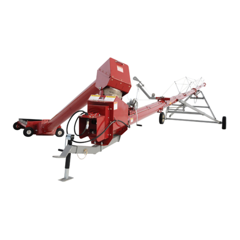
Meridian HARVEST T832 User manual

T832,T836,&T842AUGERASSEMBLYMANUAL
Read&understandallinstructionspertainingtothisaugerpriortouse!

Page2of14
Safety Alert
Watch for this ALERT Symbol. It identifies potential hazards to Personal SAFETY and
your HEALTH. It points out Safety precautions.
This SAFETY symbol means:
ATTENTION:
BE ALERT
Why is SAFETY important to you?
THREE BIG REASONS:
*ACCIDENTS DISABLE AND KILL
*ACCIDENTS COST
*ACCIDENTS CAN BE AVOIDED
Failure to read this Auger manual before operation of the Auger is a misuse of the
equipment and a needless risk to your HEALTH and SAFETY. Your life and limbs are
worth keeping. Use this equipment with care.
Symbol
Signal Words:
DANGER, WARNING, CAUTION
The appropriate signal word for each message has been selected using the following
guidelines below the Alert Symbol.
BE ALERT!
D
D
DA
A
AN
N
NG
G
GE
E
ER
R
R–Indicates an imminently hazardous situation that, if not avoided, will result
in death or serious injury. This signal word is to be limited to the most extreme situations,
typically for machine components that, for functional purposes, cannot be guarded.
W
W
WA
A
AR
R
RN
N
NI
I
IN
N
NG
G
G–Indicates a potentially hazardous situation that, if not avoided, could result
in death or serious injury, and includes hazards that are exposed when guards are
removed. It may also be used to alert against unsafe practices.
C
C
CA
A
AU
U
UT
T
TI
I
IO
O
ON
N
N
–Indicates a potentially hazardous situation that, if not avoided, may result
in minor or moderate injury. It may also be used to alert against unsafe practices.

Page3of14
TABLE OF CONTENTS
……………………………………………….. 5
……………………………………………….. 6
……………………………………………….. 7
……………………………………………….. 8
……………………………………………….. 8
……………………………………………….. 9
……………………………………………….. 12
Tube Identification
Step 1
Tube & Flighting Assembly
Steps 2 & 3
Standard Infeed Installation
Steps 4 & 5
Winch Installation
Step 6
Top Guard Installation
Step 7
Carriage Assembly
Steps 8-14
Lift Cable Assembly
Step 15
Parts Book Drawings ……………………………………………….. 14

Page4of14
T832 w/Standard Infeed & PTO Drive Option

Page5of14
Step 1
Tube Identification
1st Tube T832
Discharge Tube, T832, T836, & T842
1st Tube T836
1st Tube T842

Page6of14
Step 2 (Tube & Flighting Assembly)
Place the 1st & 2nd tubes on assembly stands. Place stands 12” or less from the end of the tube. Placing stands
further than 12” from end of the tube may cause damage to the tubes.
Step 3
Slide the flighting together from the 1st & 2nd tube. Connect the flighting using (2) 1/2" x 2” hex bolts and top
lock nuts. Align flighting as shown to make continuous. After connecting the flighting, slide the 1st & 2nd tube
together putting in the (8) 3/8" x 1” flange bolts & nuts.
Fig. 2.1
Fig. 3.1

Page7of14
Step 4 (Standard Infeed Installation)
The standard infeed will now be installed. (If installing a flex hopper, skip Step 4 & 5. Refer to T8 Hopper
Assembly Manual for installation). Place stub shaft (10282) into to end of the infeed flighting. Attach using a
1/2" x 2-1/2” hex bolt & top lock nut. Next, attach the brass bushing (30801) to the infeed housing assembly
using (4) 3/8” x 1” hex flange bolts & hex flange nuts.
Step 5
Slide the infeed housing assembly over the flighting and 1st auger tube. Align the slot in the bottom of the
infeed housing with the key stock welded to the bottom of the tube. Also, align the stub shaft in the fighting
with the bushing bolted to the infeed housing and slide stub shaft into the bushing. Attach the infeed housing to
the tube using (4) 3/8” x 1-1/4” hex flange bolts & hex flange nuts. Next, slide the hitch into the side channels
and secure using (2) 1/2" bent pins and hairpins provided.
Fig. 4.1
Fig. 5.1
Fig. 4.2

Page8of14
REFER TO DRIVE OPTION ASSEMBLY MANUALS AT THIS POINT!!!
Step 6 (Winch Installation)
After the drive option is assembled on to the auger the winch will need to be installed. To install the winch,
fasten it to the bracket welded on the underside of the first tube. Secure it to the bracket by using (3) 3/8” x 1”
hex flange bolts & nuts as shown in fig. 6.1. (If handle is not installed on the winch refer to the operator’s
manual for the winch that is provided)
Step 7 (Top Guard Installation)
Next, the top drive galvanized guards need to be assembled onto the discharge tube. Place the guards over the
top drive brackets as shown in fig. 7.1. Overlap the lower guard with the top guard as shown in fig. 7.2. Attach
the 2 guards using a total of (14) #12 x 3/4" long self tapping screws. (See fig. 7.2)
Fig. 6.1

Page9of14
Step 8 (Carriage Assembly)
Place the axle underneath the auger tubes on the stands. Attach the carriage are & hub assembly to the axle
using (4) 1/2" x 1-1/2” hex flange bolts and flange nuts. (See fig. 7.1) Do this same step on the other side of the
axle.
Step 9
Align and place the wheel on to the hub being sure the fill stem is towards the outside. Secure the wheel to the
hub using (5) 1/2" lug nuts. Tighten the lug nuts evenly using a “star” pattern. Repeat this step to assemble the
hub & wheel on the other side.
Fig. 8.1
Fig. 7.1 Fig. 7.2

Page10of14
Step 10
Next, lift the carriage arms up to the carriage mount bracket welded onto the first tube. Attach the carriage arms
as shown in fig. 9.1 using (2) 3/4" x 1-1/2” hex bolt & top lock nut.
Step 11
Next, the lift roller will be assembled to the lift arms. Place the lift roller housing bracket (10929) up to one of
the lift arms and align the holes. Take the 3/4" x 6-1/2” hex flange bolt and put it through the arm & one side of
the bracket. Slide a 3/4" washer onto the bolt. Place the lift roller (30733) in the housing and push the bolt
through the roller. Place the 2nd washer between the roller and the other side of the lift roller housing. Now,
Fig. 9.1
Fig. 10.1

Page11of14
push bolt all the way through the housing. Attach other lift arm onto bolt & secure with a 3/4" top lock nut.
The lift arms, housing, & roller should now be assembled together.
Step 12
Next, slide the lift arms and the lift roller onto the track on the underside of the discharge tube. After this is
done bolt on the lift roller stop using (2) 3/8” x 1” hex flange bolts & flange nuts. (If assembling a T832 bolt
the stop onto the track using the top set of holes; T836 bolt stop onto track using the 2nd set of holes; T842 bolt
stop onto track using 3rd set of holes in track.)
Step 13
Using a lifting strap, lift up the auger in front of the discharge spout until the lift arms align with the top holes in
the axle. When the arms align, fasten them to the axle using (2) 3/4" x 1-1/2” hex bolt & top lock nut. No not
over tighten as the lift arms need to be able to rotate on the axle. The auger should now be up on the wheels.
(If assembling a T832 skip to Step 15)
Fig. 11.1
Fig. 12.1
Fig. 11.2
Fig. 12.2
T832
T836
T842

Page12of14
Step 14 (T836 & T842 Only)
When assembling a T836 & T842 “X” bracing is required on the lift arms. Attach the bracing to the lift arms
using (5) 3/8” x 1” hex flange bolts & flange nuts. Cross the braces as shown in fig. 14.1.
Step 15 (Lift Cable Assembly)
Next, attach the lift cable to the winch by sticking one end through the side of the drum and fastening the cable
to the outside of the drum. For more information refer to winch manual included with auger. Route the cable
up around the lift roller (Fig. 15.2) going from the bottom around the top. Next, pull the cable to the bottom of
the discharge tube at wrap cable around the cable stop (30993) as shown if Fig. 15.3. Secure cable around the
Fig. 13.1 Fig. 13.2
Fig. 14.1

Page13of14
cable stop using (2) 1/4" cable clamps. After clamps are tightened, track the cable on the winch by slowing
turning the handle and guiding the cable on to the drum so it spools properly.
Step 16
Next, attach the manual canister to one of the carriage arms using 2 zip ties provided. To secure the canister to
the arm with a #12 x 3/4" self tapping screw. This will prevent the canister from sliding on the arm.
Fig. 15.1 Fig. 15.2
Fig. 15.3

Page14of14
This will complete the assembly for your Harvest by Meridian T832, T836, or T842 grain auger.
For additional part numbers, information, & overall views please refer to the parts book drawings
located at the end of this assembly manual or log onto www.harvestauger.com.
Fig. 16.3

3
X1
4
X1
5
X1
A
1
X1
2
X2
ITEM NO.
PART NO.
DESCRIPTION
QTY
1 10956
CABLE, LIFT, 1/4" x 7 x 9 x 35FT
1
2 10957
CLAMP, 1/4" CABLE
2
3
PBT08001
TUBE ASSEMBLY, INFEED, T0832
1
4
PBT08002
TUBE ASM,DISCHARGE, T08XX
1
5
PBT10003
FRAME ASSEMBLY
1
PART/ASSEMBLY DESCRIPTION
REV
AUGER MODEL(S)
DRAWING NO.
T0832 AUGER ASSEMBLY
PBT0832
T0832

2
X1
X1
3
4
X3
X8
1
X1
5
5
X3
PBT08001
AUGER MODEL(S)REV TUBE ASSEMBLY, INFEED, T832
DRAWING NO.
PART/ASSEMBLY DESCRIPTION
T832
ITEM NO. PART NO. DESCRIPTION QTY
1 30108 WINCH ASSY, 1500 LB, BRAKE 1
2 30892 TUBE ASSEMBLY, LOWER AUGER, T0832 1
3 30894 FLIGHTING ASSEMBLY, LOWER, T0832 1
4 40025 BOLT, 3/8-16UNC X 1" HEX FLANGE, GRD 5, ZINC 3
5 40056 NUT, 3/8-16UNC, HEX FLANGE, GRD 5, ZINC 11

AUGER MODEL(S)REV T832, T836, T842
PBT08002
PART/ASSEMBLY DESCRIPTION
A
DRAWING NO.
TUBE ASM,DISCHARGE, T8XX
X1
38
X1
X1
29
X1
2
12
X1
X1
X1
5
42
24
X2
X1
X1
23
14
X8
X2 X1
X8
4
36
8
X1 X1
33
35
X1
X4
628
22
X4
X1
15
25
X1 X1
19
X1
17
1
X2
32
20
34
X1
7
X1
X6
27
21
X2
X1 DETAIL A
X2
34
X2
39
X1
X8
31
26
X1
10
41 X1
X12
X2
X12
37
36 11
X2
40
31 36
X2
3
X14
X2
X20
DETAIL B
31
13
X2
X4 X4
36
9
30 36
X20
A
X1
18
16
X1
B

ITEM NO. PART NO. DESCRIPTION QTY
1 10248 SPROCKET, #60, 20 TOOTH, 1-1/4" BORE 1
2 10250 CONNECTOR LINK, #60 ROLLER CHAIN 1
3 10304 SCREW, SELF TAPPING, #12 x 3/4" 14
4 10309 KEY, 1/4 X 1-1/2", SQUARE 2
5 10339 PLUG, 3/8" NPT, FOR OIL BATH CHAIN CASE 1
6 10595 WASHER, SPACER, DRAG AUGER DRIVE SHAFT 1
7 10824 LINK, HALF, #60 OFFSET 1
8 10933 SPROCKET, 60B20 x 1" THRU BORE 1
9 10942 SHIELD, LONG, DRIVE SHAFT, T AUGERS 2
10 10944 SHAFT, DRIVE, UPPER, T1032, T0832 1
11 10950 COUPLER, SHAFT TO SHAFT, DRIVE, T10XX, T08XX 1
12 10954A SEAL,(GASKET) CHAIN GUARD COVER,T10XX T08XX 1
13 10959 STOP, LIFT ROLLER, T AUGERS 2
14 10965 GASKET, UPPER BEARING, T10XX, T08XX 1
15 11401 PIN, ROLL, 7/32" X 1-1/2", ZINC 1
16 11436 RAIL, SHORT, T8XX, T1032, T1042 1
17 11439 GASKET, LOWER BEARING, T08XX 1
18 11442 RAIL, LONG, T8XX, T1032, T1042 1
19 12063 CHAIN, ROLLER, #60 X 40 ROLLERS 1
20 12109 TUBE, IDLER, UHMW, 1-1/2" LONG 1
21 30551 1" 2 BOLT FLANGETTES W/FAFNIR BEARING 6
22 30552 BEARING, 1-1/4", 4 BOLT CAST, LOCK COLLAR 1
23 30563 1", 2 BOLT CAST FLANGE, W/BEARING 1
24 30739 HOUSING, CHAIN GUARD, WITH PLUG, T10XX, T08XX 1
25 30893 TUBE ASSEMBLY, DISCHARGE, T0832 1
26 30895 FLIGHTING ASSEMBLY, UPPER, T08XX 1
27 30993 CABLE STOP, BOLT ON, T AUGERS 1
28 40005 BOLT, 1/2-13UNC X 1-1/2" HEX FLANGE, GRD 5, ZINC 4
29 40008 BOLT, 1/2-13UNC X 2-1/2" CARRIAGE, GRD 5, ZINC 1
30 40024 BOLT, 3/8-16UNC X 1" CARRIAGE, GRD 5, ZINC 20
31 40025 BOLT, 3/8-16UNC X 1" HEX FLANGE, GRD 5, ZINC 14
32 40034 BOLT, 3/8-16UNC X1-1/2" HEX FLANGE, GRD 5, ZINC 2
33 40047 NUT, 1/2-13UNC, HEX FLANGE, GRD 5, ZINC 4
34 40048 NUT, 1/2-13UNC, HEX, TOPLOCK, ZINC 3
35 40051 NUT, 1/4-20UNC, HEX, NYLOCK, ZINC 8
36 40056 NUT, 3/8-16UNC, HEX FLANGE, GRD 5, ZINC 30
37 40059 NUT, 5/16-18UNC, HEX FLANGE, GRD 5, ZINC 12
38 40066 WASHER, FLAT, 1/2", ZINC 1
39 40082 BOLT, 1/2-UNC13 X 2" HEX, GRD 5, ZINC 2
40 40087 BOLT, 5/16-18UNC X 1", CARRIAGE, GRD 5, ZINC 12
41 40088 BOLT, 3/8-16UNC X 2 HEX FLANGE, GRD 5, ZINC 2
42 40111 BOLT, 1/4-20UNC X 1" HEX FLANGE, GRD 5, ZINC 8
AUGER MODEL(S)
DRAWING NO.
REV
PBT08002
TUBE ASM,DISCHARGE, T8XXT832, T836, T842 PART/ASSEMBLY DESCRIPTION
A

X2
4
16
X2
DETAIL C
1
X2
5
X2
14
X2
B
A
X1
10
X1
10
X1
7
X1
9
9
X1
C
X1
17
X1
DETAIL B
X2
15
311
X1
14
X1
X2
X8
13
DETAIL A
12 X10
2
X2
6
X8
X2
8
16 14
X2
DRAWING NO.
PART/ASSEMBLY DESCRIPTION
REV AUGER MODEL(S) FRAME ASSEMBLY
PBT10003
T1032, T832

PBT10003
PART/ASSEMBLY DESCRIPTION
REV AUGER MODEL(S) FRAME ASSEMBLY
DRAWING NO.
T1032, T832
ITEM NO. PART NO. DESCRIPTION QTY
1 10304 SCREW, SELF TAPPING, #12 x 3/4" 1
2 10434 NUT, 1/2-20, 60 DEGREE LUG NUT, ZINC 10
3 10929 HOUSING, LIFT ROLLER, T10XX, T08XX 1
4 10960 TIE, ZIP, MANUAL CANISTER MOUNT 2
5 30102 CANISTER, OWNERS MANUAL 1
6 30618 ST175 xD13" BIAS PLY TIRE & RIM 2
7 30729 AXLE ASSEMBLY, T1032, T0832 1
8 30730 SPINDLE ASSEMBLY, T10XX, T08XX 2
9 30731 TUBE ASSEMBLY, CARRIAGE, T1032, T0832 2
10 30732 TUBE ASSEMBLY, LIFT ARM, T1032, T0832 2
11 30733 ROLLER ASSEMBLY, LIFT, T AUGERS 1
12 40005 BOLT, 1/2-13UNC X 1-1/2" HEX FLANGE, GRD 5, ZINC 8
13 40047 NUT, 1/2-13UNC, HEX FLANGE, GRD 5, ZINC 8
14 40055 NUT, 3/4-10UNC, HEX, TOPLOCK, ZINC 5
15 40068 WASHER, FLAT, 3/4", ZINC 2
16 40090 BOLT, 3/4-10UNC x 1-1/2", HEX, GRD 5, ZINC 4
17 40112 3/4-10UNC X 6-1/2" HEX FLANGE, GRD 5, ZINC 1
This manual suits for next models
2
Table of contents
Other Meridian Tools manuals

Meridian
Meridian HARVEST T Series User manual

Meridian
Meridian HARVEST T852 User manual

Meridian
Meridian SLMD Series User manual

Meridian
Meridian HVST H10 Reference manual

Meridian
Meridian HARVEST T862 User manual

Meridian
Meridian HARVEST T1342 User manual

Meridian
Meridian HARVEST T1062 User manual

Meridian
Meridian HARVEST H1392 User manual

Meridian
Meridian SLMD10 Guide

Meridian
Meridian SLMD Series User manual