Hazet 4902/6 User manual
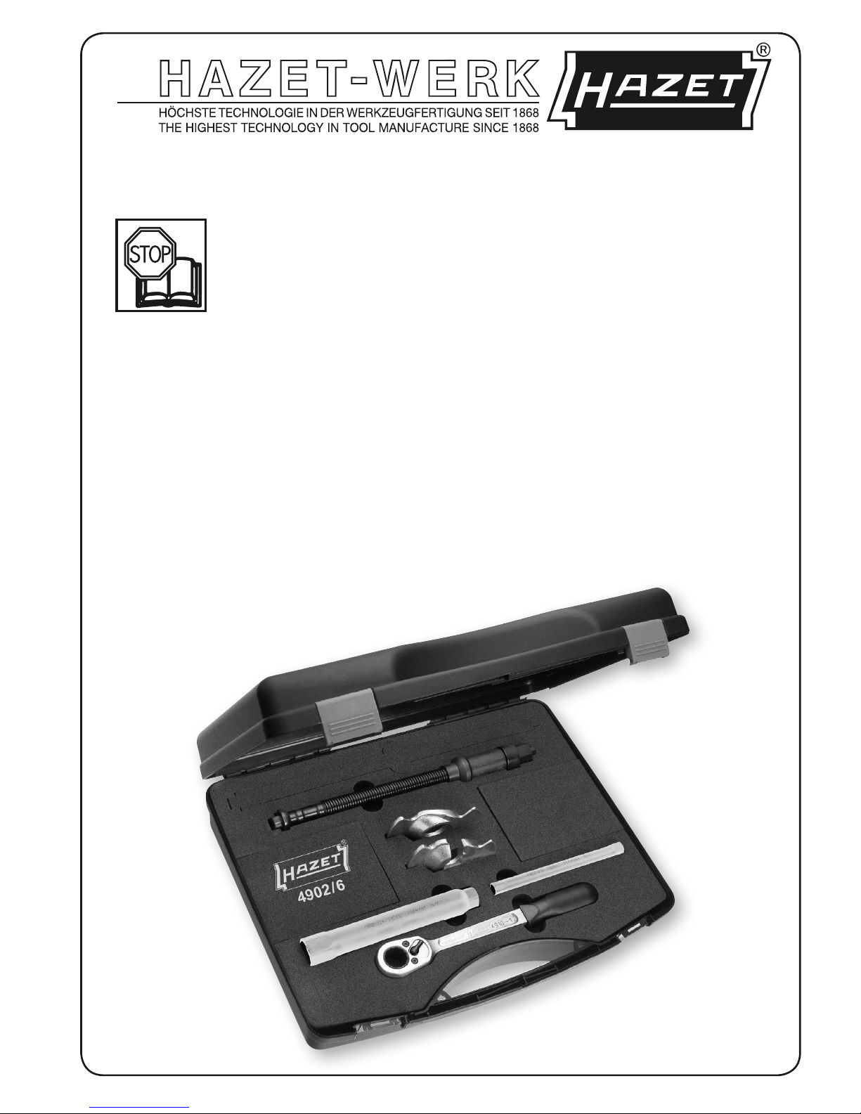
4902/6
Sicherheits-Innen-Federspanner
Safety Inside Spring Vice
Compresseur de ressort intérieur
de sécurité
Compresor de muelles interior
de seguridad
Binnenveerspanner
Tendimolle interno di sicurezza
222437
2
. . . . . . . . . . . . . . . . . . . . . . . . . . 3 – 8
. . . . . . . . . . . . . . . . . . . . . . . . . 9 – 14
. . . . . . . . . . . . . . . . . . . . . . . . . 15 – 20
. . . . . . . . . . . . . . . . . . . . . . . . . 21 – 26
. . . . . . . . . . . . . . . . . . . . . . . . . 27 – 32
. . . . . . . . . . . . . . . . . . . . . . . . . 33 – 38
HAZET-WERK Hermann Zerver GmbH & Co. KG • ;Güldenwerther Bahnhofstraße 25 - 29
42857 Remscheid • GERMANY • }10 04 61 • 42804 Remscheid • [+49 (0) 21 91 / 7 92-0
Ursprungsprache: deutsch – Original language: German – Langue d’origine: allemand
Idioma de origen: alemán – Originele taal: Duits – Lingua originale: tedesco

3
1Zu Ihrer Information
1. Allgemeine Informationen
• Bitte stellen Sie sicher, dass der Benutzer
dieses Werkzeugs die vorliegende Betriebs-
anleitung vor der ersten Inbetriebnahme
gründlich durchgelesen und verstanden hat.
• Diese Betriebsanleitung enthält wichtige
Hinweise, die zum sicheren und störungsfreien
Betrieb Ihres HAZET-Innen-Federspanners
erforderlich sind.
• Zum bestimmungsgemäßen Gebrauch des
Innen-Federspanners gehört die vollständi-
ge Beachtung aller Sicherheitshinweise und
Informationen in dieser Betriebsanleitung.
• Bewahren Sie deshalb diese Betriebs-
anleitung und den Sicherheitshinweis immer
bei Ihrem HAZET-Innen-Federspanner auf.
• Dieses Werkzeug wurde für bestimmte
Anwendungen entwickelt. HAZET weist aus-
drücklich darauf hin, dass dieses Werkzeug
nicht verändert und/oder in einer Weise ein-
gesetzt werden darf, die nicht seinem vor-
gesehenen Verwendungszweck entspricht.
• Für Verletzungen und Schäden, die aus
unsachgemäßer und zweckentfremdeter
Anwendung bzw. Zuwiderhandlung gegen die
Sicherheitsvorschriften resultieren, übernimmt
HAZET keine Haftung oder Gewährleistung.
• Darüber hinaus sind die für den
Einsatzbereich des Gerätes geltenden
Unfallverhütungsvorschriften und allgemei-
nen Sicherheitsbestimmungen einzuhalten.
2. Symbolerklärung
Achtung: Schenken Sie diesen Symbolen
höchste Aufmerksamkeit!
BETRIEBSANLEITUNG LESEN!
Der Betreiber ist verpflichtet die
Betriebsanleitung zu beachten und
alle Anwender des HAZET Innen-
Federspanners gemäß der
Betriebsanleitung zu unterweisen.
HINWEIS!
Dieses Symbol kennzeichnet Hinweise,
die Ihnen die Handhabung erleichtern.
WARNUNG!
Dieses Symbol kennzeichnet wichtige
Beschreibungen, gefährliche
Bedingungen, Sicherheitsgefahren bzw.
Sicherheitshinweise.
ACHTUNG!
Dieses Symbol kennzeichnet Hinweise,
deren Nichtbeachtung Beschädigungen,
Fehlfunktionen und/oder den Ausfall des
Gerätes zur Folge haben.
3. Haftung und
Gewährleistung
• Jede über die bestimmungsgemäße
Verwendung hinausgehende und/oder
andersartige Verwendung des Gerätes ist unter-
sagt und gilt als nicht bestimmungsgemäß.
•Ansprüche jeglicher Art gegen den Hersteller
und/oder seine Bevollmächtigten wegen
Schäden aus nicht bestimmungsgemäßer
Verwendung des Gerätes sind ausgeschlossen.
• Für alle Schäden bei nicht bestimmungsge-
mäßer Anwendung haftet allein der Betreiber.
4. Ersatzteile
• Nur Original-Ersatzteile des
Herstellers verwenden.
•Falsche oder fehlerhafte Ersatzteile kön-
nen zu Beschädigungen, Fehlfunktionen
oder Totalausfall des Gerätes führen.
•Bei Verwendung nicht freigegebener Ersatzteile
verfallen sämtliche Garantie-, Service-, Sch-
adenersatz- und Haftpflichtansprüche gegen
den Hersteller oder seine Beauftragten,
Händler und Vertreter.
5. Entsorgung
• Zur Aussonderung Gerät reinigen
und unter Beachtung geltender Arbeits-
schutz- und Umweltschutzvorschriften zerlegen.
Bestandteile der Wiederverwertung zuführen.
• Metallische Materialreste verschrotten.
4
2Zu Ihrer Sicherheit
Dieser Abschnitt gibt einen
Überblick über alle wichtigen
Sicherheitsaspekte für einen
optimalen Schutz des Personals
sowie sicheren und störungsfreien Betrieb
des Gerätes. Zusätzlich beinhalten die
einzelnen Kapitel konkrete, mit Symbolen
gekennzeichnete Sicherheitshinweise
zur Abwendung unmittelbarer Gefahren.
Darüber hinaus sind am Gerät befindliche
Piktogramme, Schilder und Beschriftungen
zu beachten und in ständig lesbarem
Zustand zu halten.
1. Allgemeines
• Das Gerät ist zum Zeitpunkt seiner Ent-
wicklung und Fertigung nach geltenden,
anerkannten Regeln der Technik gebaut und
gilt als betriebssicher. Es können vom Gerät
jedoch Gefahren ausgehen, wenn es von
nicht fachgerecht ausgebildetem Personal,
unsachgemäß oder nicht bestimmungsge-
mäß, verwendet wird. Jede Person, die mit
Arbeiten am oder mit dem Gerät beauftragt
ist, muss daher die Betriebsanleitung und
den Sicherheitshinweis vor Beginn der
Arbeiten gelesen und verstanden haben.
• Veränderungen jeglicher Art sowie An- oder
Umbauten am Gerät sind untersagt.
• Alle Sicherheits-, Warn- und Bedienungs-
hinweise am Gerät sind in stets gut lesba-
rem Zustand zu halten. Beschädigte Schilder
oder Aufkleber müssen sofort erneuert
werden.
•Angegebene Einstellwerte oder -bereiche
sind unbedingt einzuhalten.
2. Verantwortung des Betreibers
•Betriebsanleitung und Sicherheitshinweis
stets in unmittelbarer Nähe des Gerätes auf-
bewahren.
•Gerät nur in technisch einwandfreiem und
betriebssicherem Zustand betreiben.
• Sicherheitseinrichtungen immer frei erreich-
bar vorhalten und regelmäßig prüfen.
•Neben den Arbeitssicherheitshinweisen in
dieser Betriebsanleitung sind die für den Ein-
satzbereich des Gerätes allgemein gültigen
Sicherheits-, Unfallverhütungs- und Umwelt-
schutzvorschriften zu beachten und einzu-
halten.
3. Bestimmungsgemäße
Verwendung
Die Betriebssicherheit ist nur bei
bestimmungsgemäßer Verwendung
entsprechend der Angaben in der
Betriebsanleitung gewährleistet.
Neben den Arbeitssicherheits-Hinweisen
in dieser Betriebsanleitung sind die für den
Einsatzbereich des Gerätes allgemein
gültigen Sicherheits-, Unfallverhütungs- und
Umweltschutz-Vorschriften zu beachten und
einzuhalten.
• Der HAZET Innen-Federspanner dient zur
Demontage und Montage von geraden
Schraubenfedern an Pkw. Die Benutzung des
Innen-Federspanners an konischen Federn ist
nur mit speziellen Spannplatten für konische
Federn zulässig.
• Optimal abgestimmt auf die beengten
Platzverhältnisse bei der Demontage und
Montage der Schraubenfedern an der
Hinterachse folgender Fahrzeuge:
BMW 1er; E87: 116i; 118d; 120i; 120d;
E87: 118i ab Bj. 2004
BMW 3er; E90: 320i; 320d; 325i; 330i Lim
ab Bj. 2004; E91: 320, 325; 330 Touring ab Bj.
2005
•Spannplatten passend zur Feder auswählen.
• Die geschmiedeten und vergüteten
Spannplatten und die vergütete Spindel sowie
die vergüteten Antriebsteile ermöglichen die
hohe Belastbarkeit von 22.000 N.
•Die jeweils gültigen Reparaturanweisungen der
Fahrzeughersteller sind zwingend zu berück-
sichtigen.
•Jede über die bestimmungsgemäße Verwen-
dung hinausgehende und/oder andersartige
Verwendung des Gerätes ist untersagt und gilt
als nicht bestimmungsgemäß.

5
2Zu Ihrer Sicherheit
• Ansprüche jeglicher Art gegen den Hersteller
und/oder seine Bevollmächtigten wegen
Schäden aus nicht bestimmungsgemäßer
Verwendung des Gerätes sind ausgeschlos-
sen.
•Für alle Schäden bei nicht bestimmungs-
gemäßer Verwendung haftet allein der
Betreiber.
4. Aufbewahrung / Lagerung
Das Gerät ist unter folgenden
Bedingungen zu lagern und aufzube-
wahren:
• Gerät nicht im Freien aufbewahren
• Gerät trocken und staubfrei lagern
• Gerät keinen Flüssigkeiten und
aggressive Substanzen aussetzen
• Lagertemperatur -10 bis +45°C
• Relative Luftfeuchtigkeit max. 60%
5. Gefahren die vom Gerät
ausgehen
1. Vor jeder Benutzung ist der Innen-
Federspanner auf seine volle Funk-
tionsfähigkeit zu überprüfen. Ist die
Funktionsfähigkeit nach dem Ergebnis
dieser Überprüfung nicht gewährleistet
oder werden Schäden festgestellt, darf
der Innen-Federspanner nicht verwendet
werden. Ist die volle Funktionsfähigkeit
nicht gegeben und wird der Innen-
Federspanner dennoch verwendet,
besteht die Gefahr von erheblichen
Körper-/Gesundheits- und Sachschäden.
Volle Funktionsfähigkeit ist gegeben,
wenn:
das Gerät leichtgängig ist
(Spindel 1vor jedem Gebrauch fetten);
der Aufnahmekopf der Spindel keine
Beschädigung aufweist;
die Madenschraube 1aam Ende der
Spindel eingesetzt ist (Endanschlag);
das Lager der Antriebsmutter 2
leichtgängig ist.
die Spannplatten 4und 5keine
Beschädigungen aufweisen.
2. Beim Spannen der Feder ist darauf zu
achten, dass sich die Federwindungen
nicht berühren, weil es sonst zu einer
Überlastung und somit zum Bruch der
Spindel kommen kann.
3. Es dürfen nur geeignete Spannplatten
eingesetzt werden. (Anwendung Seite 7)
4. Die Feder (Bild 4 Seite 8) muß ausser-
halb der Innenrippe der Spannplatte
liegen. Es ist darauf zu achten, daß
ein Herausgleiten der Feder aus den
Spannplatten nicht möglich ist.
5. Spannplatten dürfen nur in der dafür vor-
gesehenen Zusammenstellung eingesetzt
oder ausgetauscht werden.
6. Aus Sicherheitsgründen sind
Veränderungen am Innen-Federspanner
strengstens untersagt. Die Vornahme von
Veränderungen am Innen-Federspanner
führt zum sofortigen Haftungsausschluß.
–
–
–
–
–

6
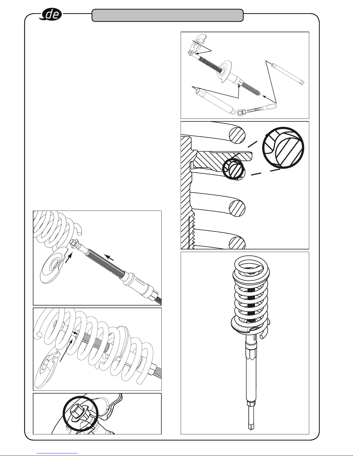
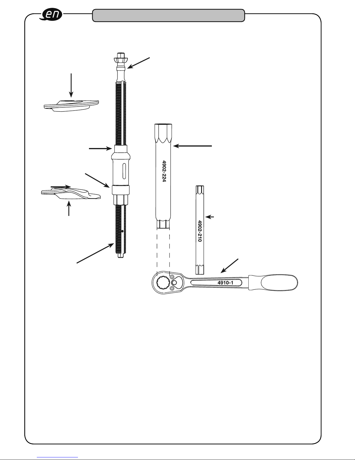
3Aufbau und Funktion
4
Obere Spannplatte
4902-10
1
Spindel
3
Druckstück
6
Rohr-Doppelsteckschlüssel
Ä24
7
Rohr-Doppelsteckschlüssel
Ä10
8
Umschaltknarre
2
Antrieb
1
Madenschraube
5
Untere Spannplatte
4902-11
a
1. Geräteelemente
Grundgerät 4902-1
1 Spindel
2 Antrieb
3 Druckstück
Spannplatten 4902-10, 4902-11
4 Obere Spannplatte, offen
5 Untere Spannplatte, geschlossen
Werkzeuge
6 Rohr-Doppelsteckschlüssel Ä24
7 Rohr-Doppelsteckschlüssel Ä10
8 Umschaltknarre
2. Technische Daten
Grundgerät: 4902-1
Max. Druckkraft: 22000 N
Max. Antriebsmoment: 100 Nm
Spindellänge: 340 mm
Spannweg: 180 mm
Für Schraubenfedern
mit einem minimalen
Innendurchmesser von Ø: 65 mm

7
3Aufbau und Funktion
3. Wartung und Pflege
• Gerät stets sauber halten. Keine entfetten
den Mittel oder Wasser verwenden, da sonst
Korrosion entsteht.
• Bei allen Rückfragen und Ersatzteilbestellungen
bitte unbedingt die Artikelnummer des Gerätes
angeben.
• Die Spindel des Innen-Federspanners 4902-1 ist
im Gewindebereich zu fetten.
Wir empfehlen:
Walkpenetration 265/295 KP2R/DIN
51502 und DIN 51825.
•Überprüfung und Reparatur sind ausschließlich
durch den Hersteller vorzunehmen.
4. Anwendung
Demontage und Montage der
Schraubenfedern an der Hinterachse
folgender Fahrzeuge:
• Spannplatten: 4902-10 oben
4902-11 unten
BMW 1er; E87: 116i; 118d; 120i; 120d;
E87: 118i ab Bj. 2004
BMW 3er; E90: 320i; 320d; 325i;
330i Lim ab Bj. 2004; E91: 320, 325;
330 Touring ab Bj. 2005
• Der patentierte Pendel-6kt-Kopf mit
integriertem Verdrehschutz verteilt die Kraft
gleichmäßig.
•Die patentierte Innenführung der Spannplatten
verhindert des Herausrutschen der Feder.
• Gegenhalten der Spindel am Pendel-6kt-Kopf
ist möglich.
• Spannplatten passend zur Feder auswählen.
–
–
4
Obere Spannplatte,
offen
7
Rohr-Doppelsteckschlüssel
Ä10
6
Rohr-Doppelsteckschlüssel
Ä24
8
Umschaltknarre
5
Untere Spannplatte,
geschlossen
1
Spindel
8
4
7
6
8
5
1
3Aufbau und Funktion
• Untere Spannplatte
5
von der Seite in die
Feder einführen Bild 1.
• Spindel inklusive Druckstück und Antrieb von
unten durch den Querlenker und die Feder
nach oben bis zur Backe schieben.
• Obere Spannplatte
4
auf die Spindel
auffädeln Bild 2.
•Die Sechskantkalotte der Spindel
1
von oben in die Aufnahme der oberen
Spannplatte absenken. Bild 3.
• Sitz der Sechskantkalotte auf richtige
Anordnung prüfen Bild 3.
• Das System vorspannen und den Sitz der
Feder rundum an der Innenführung kontrollie-
ren Bild 4.
•Mit Hilfe des Rohrschlüssels
6
und der
Umschaltknarre
8
den Antrieb betätigen
Bild 5.
•Bei Lösen der Feder aus den Halterungen/
Gummiaufnahmen mit Hilfe des
Rohrschlüssels
7
gegenhalten Bild 5 um
das Verdrehen/Mitdrehen zu verhindern.
Bild 1
Bild 2
Bild 3
Bild 4
Bild 5

9
1For your information
1. General information
• Please take care that the user of this tool care-
fully reads through these operating instruc-
tions and understands all information given in
there before the first use.
•These operating instructions contain impor-
tant advices that are necessary for a safe and
trouble-free operation of your HAZET Inside
Spring Vice.
• For effective use of the Inside Spring Vice as
intended, it is essential that all safety instruc-
tions and other information in these operating
instructions is adhered to.
• For this reason, always keep these operating
and safety instructions together with your
HAZET Inside Spring Vice.
• This tool has been designed exclusively for
particular applications. HAZET emphasizes
that any modification of this tool and/or an
application that does not correspond to its
intended application are strictly forbidden.
• HAZET will not be liable for any injuries to per-
sons or damages to property that are due to
an improper application or misuse of this tool
respectively due to the disregard of the safety
instructions.
• Furthermore, the general safety regulations,
regulations for the prevention of accidents
and regulations for environmental protection
being valid for the application area of this
device have to be observed and respected,
too.
2. Explanation of symbols
ATTENTION: Please pay attention to these
symbols!
READ THE OPERATING INSTRUCTIONS!
The operator is obliged to observe
the operating instructions and has to
instruct all users of the HAZET
Inside Spring Vice according to the
information given in this manual.
NOTICE!
This symbol marks indications which
help to you to use the device.
WARNING!
This symbol indicates important speci-
fications, dangerous conditions, safety
risks and safety advice.
CAUTION!
This symbol marks advice which if dis-
regarded results in damage, malfunction
and/or functional failure of the tool.
3. Liability and warranty
• Any deviation from the intended use
and/or any misapplication of the device are not
allowed and will be considered as improper use.
• Any claims against the fabricant and/or its
authorized agents because of damage caused
by improper use of the device are excluded.
• Any personal injury or any material losses caused
by improper use are the sole responsibility of the
operator and user.
4. Spare Parts
• Only use original spare parts of the
manufacturer.
• Unsuitable or defective spare parts
may cause damage, malfunction or the
device’s total failure.
• When using spare parts that are not approved,
all warranty claims, service claims, claims for
compensation and liability claims against the
manufacturer or its agents, distributors and
sales representatives will be void.
5. Disposal
• For disposal, clean device and disas-
semble according to the regulations for
environmental protection and work safety.
Components can be used for recycling.
•Send metal residuals to be scrapped.

10
2For Your Safety
This paragraph gives an over-
view about all important security
advices which help to ensure
the optimal protection of the
personnel as well as the safe and
trouble-free operation of the appliance.
Additionaly, the different chapters contain
concrete security advices that are marked
with symbols in order to avert immediate
danger. Furthermore, all pictograms, sti-
ckers and labels on the appliance must be
observed and have to be kept legible.
1. General aspects
• The device was developed and fabricated
according to the technical norms and stan-
dards that have been valid at that time and
is considered to be operationally reliable.
Nevertheless, the device can present a dan-
ger when it is not used as intended or in an
inappropriate way by non-qualified person-
nel. Please take care that any person using
this tool or carrying out maintenance work
carefully reads through these operating and
safety instructions and understands all infor-
mation given in there, before the first use.
•Any modification of the device is strictly for-
bidden.
•All security advices, warning and operation
notices on the device have to be kept legible.
Replace all damaged labels or stickers.
• All indications concerning setting values and
setting ranges must be observed.
2. Operator’s Liability
• Keep the operating and safety instructions
always together with the Inside Spring Vice.
•The device must only be used if it is techni-
cally faultless and operationally reliable.
•All security devices must always be within
reach and should be checked regularly.
• Apart from the safety advices given in these
operating instructions, the user of this tool
has to observe and respect the general safe-
ty regulations, regulations for the prevention
of accidents and regulations for environmen-
tal protection being valid for the application
area of this device, too.
3. Appropriate Use
Operational reliability can only be
safeguarded, if the device is used
as intended and in compliance with
the indications given in the operating
instructions. Apart from the safety advices
given in these operating instructions, the
general safety regulations, regulations for
the prevention of accidents and regulations
for environmental protection being valid for
the application area of this device have to be
observed and respected, too.
• The HAZET Inside Spring Vice is designed for
installing and removing straight coil springs
on passenger cars. For conical coil springs,
the Inside Spring Vice must only be used in
conjunction with special tensioning jaws for
conical springs.
• The Inside Spring Vice is perfectly suited to
the limited spaces when installing and remo-
ving the coil spring at the rear axle of the
following vehicles:
BMW 1-series: E 87: 116i, 118 d, 120i,
120d, E87: 118i since 2004;
BMW 3-series: E90: 320i, 320d, 325i,
330i limousine since 2004, E91: 320, 325,
330 Touring since 2005
•Select tensioning jaws to fit the spring.
• The forged and tempered tensioning jaws
and the tempered spindle as well as the
tempered driving parts allow a capacity of
22,000 N.
•The current repair instructions of the vehicle
manufacturer have to be compulsorily obser-
ved.
•Any deviation from the intended use and/or
any misapplication of the device are not allo-
wed and will be considered as improper use.
•Any claims against the fabricant and/or
its authorized agents because of damage
caused by improper use of the device are
excluded.

11
2For Your Safety
• Any personal injury or material losses caused
by improper use are the sole responsibility of
the operator and user.
4. Storage
The device has to be stored according
to the following conditions:
• The device must not be stored outdoors.
• Store the device in a dry and dust-free place.
• Do not expose the device to liquids or other
aggressive substances.
• Storage temperature: -10 up to +45°C
• Relative air humidity: max. 60%
5. Dangers emanating from
the device
1. Before each use, check the Inside Spring
Vice for full operatability. Do not use the
Inside Spring Vice if the operatability can-
not be ensured or if damage is detected.
If the Inside Spring Vice is used, although
its full operatability cannot be ensured, you
risk severe injuries to persons and damage
to property.
Full operatability is given when:
the appliance is smooth running
(spindle 1must be greased before
each use);
the spindle’s location head is absolutely
damage-free;
the headless set screw 1ais inserted at
the end of the spindle (limit stop);
the bearing of the driving nut 2 is
smooth-running;
the tensioning jaws 4and 5are
absolutely damage-free.
2. When tensioning the spring, it is important
that the spring windings do not come into
contact with each other because the spind-
le may get overloaded and may break.
3. Only use appropriate tensioning jaws (see
“Application” on page 13).
4. The spring (illustration 4, page 14) must
rest securely outside of the inner rib.
Please make sure that the spring cannot
slide out of the tensioning jaws.
5. The tensioning jaws have to be used
and changed in combination only and as
intended for their use.
6. For safety reasons, modifications of the
Inside Spring Vice are strictly forbidden.
Any modification of the Inside Spring Vice
will lead to the exclusion of liability.
–
–
–
–
–
12
3Design and Function
4
Upper Tensioning Jaw
4902-10
1
Spindle
3
Thrust Piece
6
Tubular Double Box-End Wrench
Ä24
7
Tubular Double Box-End Wrench
Ä10
8
Reversible Ratchet
2
Drive
1
Headless Set Screw
5
Bottom Tensioning Jaw
4902-11
a
1. Components of the Device
Basis Appliance 4902-1
1 Spindle
2 Drive
3 Thrust Piece
Tensioning Jaws 4902-10, 4902-11
4 Upper Tensioning Jaw, open
5 Bottom Tensioning Jaw, closed
Tools
6 Tubular Double Box-End Wrench Ä24
7 Tubular Double Box-End Wrench Ä10
8 Reversible Ratchet
2. Technical Data
Basic Appliance: 4902-1
Max. force of pressure: 22000 N
Max. driving torque: 100 Nm
Spindle length: 340 mm
Span: 180 mm
For coil springs
with a minimum
inside diameter Ø of: 65 mm
13
3Design and Function
4. Application
Installing and removing of the coil springs
at the rear axle of the following vehicles:
• Tensioning Jaws: 4902-10 upper
4902-11 bottom
BMW 1-series: E87: 116i, 118 d, 120i, 120d;
E87: 118i since 2004
BMW 3-series: E90: 320i, 320d, 325i, 330i
limousine since 2004; E91: 320, 325, 330
Touring since 2005
• The patented pendulum 6-point head with inte-
grated anti-twist protection provides a uniform
distribution of power.
•The patented internal guidance of the tensio-
ning jaws prevents the spring from sliding out.
•The spindle can be counter held at the
pendulum 6-point head.
•Select tensioning jaws to fit the spring.
–
–
3. Maintenance and Cleaning
• Always keep the Inside Spring Vice clean. Do not
use degreasing agents or water because they
produce corrosion.
• For all questions and spare part orderings,
please include the article number of the Inside
Spring Vice.
• The threaded part of the spindle of the Inside
Spring Vice 4902-1 has to be greased.
We recommend:
Worked penetration 265/295 KP2R/DIN 51502
and DIN 51825.
•Checking and repair has to be carried out
exclusively by the manufacturer.
4
Upper Tensioning Jaw,
open
7
Tubular Double Box-End Wrench
Ä10
5
Bottom Tensioning Jaw,
closed
1
Spindle
6
Tubular Double Box-End Wrench
Ä24
8
Reversible Ratchet

14
4
7
6
8
5
1
3Design and Function
• Insert bottom tensioning jaw
5
from the side
into the coil spring (figure 1).
• Push spindle, thrust piece and drive from
below through the suspension arm and the
spring upwards until reaching the bottom the
tensioning jaw.
• Push upper tensioning jaw
4
onto the
spindle (figure 2).
• Lower the splindle’s
1
6-point cap (calotte)
from the top downwards into the reception
hole of the upper tensioning jaw (figure 3).
• Check correct fit and assembly of the 6-
point cap (calotte) (figure 3).
• Pretension the system and check the spring’s
tight fit all around the internal guidance
(figure 4).
• Operate drive with the tubular box-end
wrench
6
and the reversible ratchet
8
(figure 5).
• When removing the spring from the fixing
device/rubber protectors, retain with tubular
box-end wrench
7
in order to avoid turning/
twisting of the tensioning jaw.
fig. 1
fig. 2
fig. 3
fig. 4
fig. 5

15
1Pour votre information
1. Informations générales
• Avant d’utiliser l’outil, il est absolument néces-
saire que l’utilisateur lise ce mode d’emploi
dans son intégralité et comprenne toutes les
informations données.
• Ce mode d’emploi contient des informations
importantes qui sont nécessaires pour un
travail sûr et sans dysfonctionnement de votre
compresseur de ressort intérieur HAZET.
• L’observation de toutes les consignes de
sécurité et des informations dans ce mode
d'emploi est nécessaire à l'utilisation correcte
du compresseur de ressort intérieur.
• Pour cette raison, gardez s.v.p. ce mode
d’emploi et les instructions de sécurité tou-
jours avec votre compresseur de ressort inté-
rieur HAZET.
•Cet outil a été developpé exclusivement pour
des applications particulières. HAZET attire
l’attention sur le fait que des modifications de
l’outil ou une utilisation qui ne correspond pas
à sa fonction prévue sont strictement inter-
dites.
•HAZET décline toute responsabilité quant aux
dommages matériels et corporels qui feraient
suite à l’utilisation incorrecte ou détournée de
l’outil ou bien au non-respect des instructions
de sécurité.
• De plus, il faut obligatoirement observer les
prescriptions générales de sécurité et les
prescriptions de prévention des accidents
étant valables pour le champ d’application du
dispositif.
2. Explication des symboles
ATTENTION : Faites attention à ces symboles,
s.v.p.!
LISEZ LE MODE D’EMPLOI !
L’opérateur de l’outil est obligé de
prendre connaissance du mode
d’emploi et d’instruire tous les utili-
sateurs du compresseur de ressort
intérieur HAZET selon les instruc
tions données dans ce mode
d’emploi.
NOTE!
Ce symbole marque les indications qui
facilitent le maniement du compresseur
de ressort intérieur.
AVERTISSEMENT !
Ce symbole indique des spécifications
importantes, des conditions dange-
reuses, des risques et des indications de
sécurité.
ATTENTION!
Ce symbole marque les indications,
dont le non-respect peut entraîner
l’endommagement, le dysfonctionne-
ment et/ou la défaillance de l’appareil.
3. Responsabbilité et garantie
• Toute utilisation non conforme aux
instructions et/ou toute utilisation
détournée de l’appareil est interdite et
est considérée comme inapropriée.
•Toute prétention contre le fabricant et/ou ses
agents autorisés résultant d’une utilisation inap-
propriée de l’appareil est exclue.
•D’éventuelles blessures et/ou dommages
matériels entraînés par une utilisation inappro-
priée relèvent de la responsabilité exclusive de
l’opérateur et/ou de l’utilisateur.
4. Pièces de rechange
• N’utilisez que les pièces de rechange
originales du fabricant.
• L’utilisation des pièces de rechange
inappropriées ou défectueuses peut
entraîner l’endommagement, le dysfon-
ctionnement et/ou la défaillance de l’appareil.
• L’utilisation de pièces de rechange non approu-
vées entraînera automatiquement la perte de
tous les droits de garantie, les droits de service,
les droits aux dommages et intérêts et la préten-
tion en responsabilité contre le fabricant ou ses
agents, distributeurs et représentants.
5. Evacuation
• Pour l’évacuation, nettoyez l’appareil
et démontez-le en considération des
prescriptions de sécurité au travail et des
prescriptions de protection de l’environnement
valables. Les components peuvent être amenés
au recyclage.
• Les restes de matériaux métalliques peuvent
être mis à la casse.
16
2Pour votre sécurité
Ce paragraphe donne une vue
d’ensemble de tous les aspects
importants de sécurité pour la
protection optimale du personnel
ainsi que pour un fonctionnement sûr de
l’appareil sans défaillance. De plus, les dif-
férents chapitres contiennent des avis de
sécurité concrets marqués avec des sym-
boles pour écarter les dangers immédiats.
En outre, l’étiquetage, les pictogrammes
et les vignettes doivent être respectés et il
faut les conserver bien lisibles.
1. Aspects géneraux
• L’appareil a été développé et construit selon
les normes et standards techniques qui ont
été valables à ce temps et est considéré
comme fiable. Tout de même, il y a des dan-
gers qui peuvent émaner de l’appareil s’il est
utilisé non conformément aux instructions ou
de manière détournée par un personnel non
spécialisé. Toute personne utilisant l’outil doit
impérativement lire ce mode d’emploi et les
instructions de sécurité dans son intégralité
et comprendre toutes les informations don-
nées avant de travailler avec l’appareil.
•Toute modification del’appareil est interdite.
• Tous les avis de sécurité, d’avertissement
et d’utilisation sur l’appareil doivent être
conservés bien lisibles. Les plaquettes et les
vignettes endommagées sont à remplacer
immediatément.
• Les valeurs ou les domaines de réglage doi-
vent impérativement être respectés.
2. Responsabilité de l’opérateur
•Gardez le mode d’emploi et les instructions
de sécurité toujours ensemble avec le com-
presseur de ressort intérieur.
•N’utilisez pas le dispositif si n’est pas dans
un état technique parfait et fiable.
• Les dispositifs de sécurité doivent être tou-
jours librement accessibles et doivent être
contrôlés regulièrement.
•À côté des instructions de sécurité au travail
dans le présent mode d’emploi, il faut égale-
ment observer et respecter les prescriptions
de sécurité, les prescriptions de prévention
des accidents et les prescriptions de protec-
tion de l’environnement étant valables pour le
champ d’application du dispositif.
3. Utilisation conforme aux
instructions
La sécurité de fonctionnement ne
peut être garantie que dans le cas où
le dispositif est utilisé conformément
aux indications données dans le pré-
sent mode d’emploi. À côté des instructions
de sécurité au travail dans ce mode d’emploi,
il faut également observer et respecter les
prescriptions de sécurité, les prescriptions de
prévention des accidents et les prescriptions
de protection de l’environnement étant vala-
bles pour le champ d’application du dispositif.
•Le compresseur de ressort intérieur HAZET
est prévu pour le montage et le démontage
des ressorts hélicoïdaux droits sur les véhicu-
les de tourisme. L’utilisation du compresseur
de ressort intérieur pour les ressorts hélicoï-
daux coniques n’est admissible qu’avec des
coupelles spéciales pour ressorts hélicoïdaux
coniques.
• Le compresseur de ressort intérieur est
adapté de façon optimale aux espaces
reduits lors du montage et du démontage
des ressorts hélicoïdaux de l’essieu arrière
sur: BMW série1 : E87 : 116i, 118 d, 120i,
120d, E87 : 118i à partir de 2004
BMW série 3 : E90 : 320i, 320d, 325i, 330i
limousine à partir de 2004, E91 : 320, 325,
330 Touring à partir de 2005
• Selectionnez les coupelles conformément au
ressort.
• Les coupelles forgées et trempées, la broche
trempée ainsi que les pièces d’entraînement
trempées permettent une haute capacité de
22 000 N.
•Les prescriptions du fabricant correspondant
relatives à la réparation du véhicule doivent
être impérativement respectées.

17
2Pour votre sécurité
• Toute utilisation non conforme aux instruc-
tions du présent mode d’emploi et/ou toute
utilisation détournée est interdite et est con-
sidérée comme inappropriée.
•Toute prétention contre le fabricant et/ou ses
agents autorisés résultant d’une utilisation
inappropriée de l’appareil est exclue.
• D’éventuelles blessures et/ou dommages
matériels entraînés par une utilisation inap-
propriée relèvent de la responsabilité exclusi-
ve de l’opérateur et/ou de l’utilisateur.
4. Stockage / Dépôt
L’appareil doit être stocké selon les
conditions décrites ci-après :
• Ne stockez pas l’appareil en plein air.
• Stockez l’appareil dans un endroit sec et libre
de poussière.
• N’exposez pas l’appareil à des liquides ou à
des substances agressives.
• Température de stockage : de -10 à +45°C
• Humidité relative de l’air : 60% max.
5. Dangers émanant de l’appareil
1. Vérifiez le bon fonctionnement du
compressor de ressort intérieur avant toute
utilisation. Si, lors de ce contrôle, un dysfon
ctionnement ou des endommagements sont
con statés, le compresseur de ressort intéri
eur ne doit pas être utilisé. Si le contrôle a
montré un dysfonctionnement ou un endom
magement et le compresseur de ressort inté
rieur est quand même utilisé, il existe des
risques de blessures graves et de dommages
matériels.
Le compresseur de ressort intérieur fonc-
tionne parfaitement quand :
– l’appareil marche facilement (graisser la
broche 1avant toute utilisation);
– la tête de logement de la broche ne
présente aucun endommagement;
– la goupille filetée 1aest insérée au
bout de la broche (butée de fin de course);
– le roulement de l’écrou d’entraînement 2
marche facilement;
– les coupelles 4et 5ne présentent aucun
endommagement.
2. Lors du serrage, il faut faire attention que
les spires du ressort ne se touchent pas, ce
qui peut entraîner une surcharge et, en
conséquence, la rupture de la broche.
3. N’utiliser que les coupelles appropriées
(voir « Application » à la page 19).
4. Le ressort doit être placé à l’extérieur de la
nervure intérieure. Veillez à empêcher le
glissement du ressort hors des coupelles.
5. Les coupelles seulement doivent être
utilisées et changées par paire.
6. Pour des raisons de sécurité, toute
modification du compresseur de ressort
intérieur est strictement interdite. Toute
modification du compresseur de ressort
intérieur entraînera automatiquement
l’exclusion de la responsabilité.

18
3Design et fonctionnement
a
4
Coupelle supérieure
4902-10
1
Broche
3
Pièce de pression
6
Clé tubulaire
Ä24
7
Clé tubulaire
Ä10
8
Cliquet réversible
2
Entraînement
1
Goupille filetée
5
Coupelle inférieure
4902-11
1. Eléments de l’appareil
Appareil de base 4902-1
1 Broche
2 Entraînement
3 Pièce de pression
Coupelles 4902-10, 4902-11
4 Coupelle supérieure, ouverte
5 Coupelle inférieure, fermée
Outils
6 Clé tubulaire Ä24
7 Clé tubulaire Ä10
8 Cliquet réversible
2. Informations techniques
Appareil de base : 4902-1
Compression max. : 22000 N
Couple d’entraînement max. : 100 Nm
Longueur de la broche : 340 mm
Allongement : 180 mm
Pour les ressorts
hélicoïdaux d’un
diamètre intérieur min. Ø de : 65 mm
19
3Design et fonctionnement
3. Entretien et maintenance
• Maintenez l’appareil propre. N’utilisez pas de
dégraissant ou d’eau parce qu’ils peuvent ent-
raîner l’apparition de corrosion.
•Lors de toute demande d’information et com-
mande de pièce de rechange, il est nécessaire
d’indiquer la réf. de l’appareil.
•Graissez la zone du filetage de la broche du
compresseur de ressort intérieur 4902-1.
Nous recommandons :
Pénétration travaillée 265/295 KP2R/DIN 51502
et DIN 51825
•Les contrôles et les réparations doivent être
effectués par le fabricant uniquement.
4. Application
Montage et démontage des ressorts héli-
coïdaux de l’essieu arrière des véhicules
suivants:
• Coupelles : 4902-10 supérieure
4902-11 inférieure
- BMW série 1 : E87 : 116i, 118 d, 120i,
120d, E87 : 118i à partir de 2004
- BMW série 3 : E90 : 320i, 320d, 325i,
330i limousine à partir de 2004,
E91 : 320, 325, 330 Touring à partir de
2005
• La tête à 6 pans à pendule brevetée avecpro-
tection intégrée contre la torsion permet la
distribution uniforme de force.
•Le guidage interne breveté des coupelles
empêche que le ressort sorte de la coupelle.
• Vous pouvez contre-appuyer la broche à la
tête à 6 pans à pendule.
• Choisissez les coupelles conformément au
ressort.
4
Coupelle supérieure
7
Clé tubulaire
Ä10
6
Clé tubulaire
Ä24
8
Cliquet réversible
5
Coupelle inférieure
1
Broche

20
3Design et fonctionnement
fig. 1
fig. 2
fig. 3
fig. 4
fig. 5
4
7
6
8
5
1
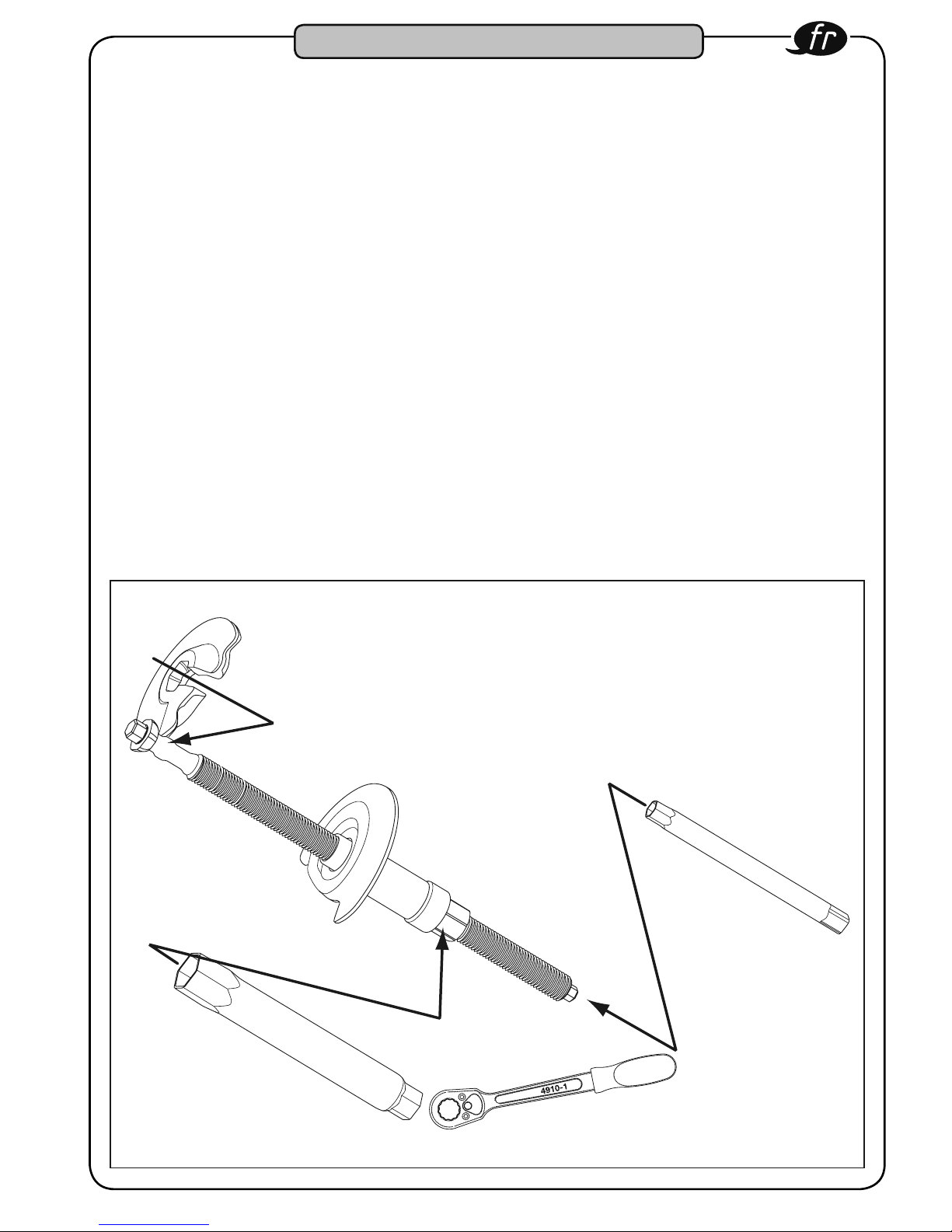
• Insérez la coupelle inférieure
5
latéralement
dans le ressort (figure 1).
• Poussez la broche ensemble avec la pièce
de pression et l’entraînement d’en bas par le
bras vers le haut jusqu’à la coupelle.
• Placez la coupelle supérieure
4
sur la
broche (figure 2).
• Baissez la calotte
1
à 6 pans de la broche
d’en haut dans le logement prévu de la cou-
pelle supérieure (figure 3).
•Contrôlez la position et le logement corrects
de la calotte (figure 3).
• Précontraignez le système et vérifiez le loge-
ment correct du ressort tout autour du guida-
ge interne (figure 4).
•Manipulez l’entraînement avec la clé tubulaire
(6) et le cliquet réversible (8) (figure 5).
• Lors de la démontage du ressort des mon-
tures/protections en caoutchouc, contre-
appuyez à l’aide de la clé tubulaire (7)
(figure 5 ) afin d’eviter que la coupelle tour-
ne/se torde.
Other manuals for 4902/6
1
Table of contents
Languages:
Other Hazet Tools manuals

Hazet
Hazet 4930 User manual

Hazet
Hazet 179 N X User manual

Hazet
Hazet 2588/7 User manual

Hazet
Hazet 9012 SPC User manual

Hazet
Hazet 4934-3478/11 User manual

Hazet
Hazet 2588/19 User manual

Hazet
Hazet 2191/12 K User manual

Hazet
Hazet 4794/48 User manual

Hazet
Hazet 9042-1 Installation and operating instructions

Hazet
Hazet 4902/6 User manual


