BFG Technologies VNF4 Ultra User manual

BFG Technologies
VNF4 Ultra
NVIDIA nForce4 Ultra
ATX Motherboard
User’s Guide

Declaration of Conformity
According to 47 CFR, Parts 2 and 15 of the FCC Rules
The following designated product:
EQUIPMENT: MAINBOARD
MODELNO.: VNF4 Ultra
is a Class B digital device that complies with 47 CFR Parts 2 and 15 of the FCC
Rules. Operation is subject to the following two conditions:
1. This device may not cause harmful interference.
2. This device must accept any interference received, including interference that
may cause undesired operation.

Federal Communications Commission Statement
This device complies with FCC Rules Part 15. Operation is subject to the following two conditions:
* This device may not cause harmful interference.
* This device must accept any interference received, including interference that may cause undesired operation.
This equipment has been tested and found to comply with the limits for a Class B digital device, pursuant to
Part 15 of the FCC Rules. These limits are designed to provide reasonable protection against harmful interference in
a residential installation. This equipment generates, uses, and can radiate radio frequency energy. If this equipment
is not installed and used in accordance with the manufacturer's instructions, it may cause harmful interference to
radio communications. However, there is no guarantee that interference will not occur in a particular installation. If
this equipment does cause harmful interference to radio or television reception, which can be determined by turning
the equipment off and on, the user is encouraged to try to correct the interference by one or more of the following
measures:
* Reorient or relocate the receiving antenna.
* Increase the separation between the equipment and receiver.
* Connect the equipment to an outlet on a circuit different from that to which the receiver is connected.
* Consult the dealer or an experienced radio/TV technician for help.
The use of shielded cables for connection of the monitor to the graphics card is required to assure compliance
with FCC regulations. Changes or modifications to this unit not expressly approved by the party responsible for
compliance could void the user's authority to operate this equipment.
Canadian Department of Communications Statement
This digital apparatus does not exceed the Class B limits for audio noise emissions from digital apparatuses
set out in the Radio Interference Regulations of the Canadian Department of Communications.
Manufacturer's Disclaimer Statement
The information in this document is subject to change without notice and does not represent a commitment
on the part of the vendor. No warranty or representation, either expressed or implied, is made with respect to the
quality, accuracy or fitness for any particular purpose of this document. The manufacturer reserves the right to make
changes to the content of this document and/or the products associated with it at any time without obligation to
notify any person or organization of such changes. In no event will the manufacturer be liable for direct, indirect,
special, incidental or consequential damages arising out of the use or inability to use this product or documentation,
even if advised of the possibility of such damages. This document contains materials protected by copyright.All
rights are reserved. No part of this manual may be reproduced or transmitted in any form, by any means or for any
purpose without expressed written consent of it's authors. Product names appearing in this document are mentioned
for identification purposes only.All trademarks, product names or brand names appearing in this document are
registered property of their respective owners.
Printed in Taiwan.
Mar 2004

CHAPTER 1 INTRODUCTION..............................................................................................................1
1-1 SPECIFICATIONS.................................................................................................................................1
1-2 BENEFITS &FEATURES......................................................................................................................3
1-3 PACKAGE CONTENTS .........................................................................................................................5
1-4 LAYOUT .............................................................................................................................................6
CHAPTER 2 HARDWARE......................................................................................................................7
2-1 PC D.I.Y.ASSEMBLY INSTRUCTIONS.................................................................................................7
2-2 JUMPERS ............................................................................................................................................9
2-3 CONNECTORS...................................................................................................................................10
CHAPTER 3 BIOS SETUPPROGRAM..............................................................................................18
3-1 STANDARD CMOS SETUP ...............................................................................................................18
3-2ADVANCED BIOS FEATURES ...........................................................................................................18
3-3ADVANCED CHIPSET FEATURES.......................................................................................................19
3-4 INTEGRATED PERIPHERALS..............................................................................................................19
3-5 POWER MANAGEMENT SETUP.........................................................................................................19
3-6 PNP/PCI CONFIGURATIONS ............................................................................................................19
3-7 PC HEALTH STATUS .........................................................................................................................19
3-8 FREQUENCY/VOLTAGE CONTROL....................................................................................................19
3-9 LOAD FAIL-SAFE DEFAULTS............................................................................................................19
3-10 LOAD OPTIMIZED DEFAULTS.........................................................................................................20
3-11 SUPERVISOR PASSWORD &USER PASSWORD SETTING .................................................................20
3-12 SAVE AND EXIT SETUP...................................................................................................................20
3-13 EXIT WITHOUT SAVING .................................................................................................................20
CHAPTER 4 SOFTWARE.....................................................................................................................21
APPENDIX...............................................................................................................................................32
A-1 INSTALLING WINDOWS 2000/XPON A SATADRIVE ......................................................................32
NOTE ........................................................................................................................................................33

Revision History
Revision Description P/N
V.1_M Original Issue 9415257010


Chapter 1
1
Chapter 1 Introduction
1-1 Specifications
CPU
-Supports AMD Socket-939 Athlon 64 FX / Athlon 64
-Processor interface via 2000MT/s Hyper Transport bus
Chipset
-NVIDIA nForce4 (VNF4) / nForce4 Ultra (VNF4 Ultra)
Memory
-Four 184- pin DDR DIMMs up to 4GB
-Supports Dual Channel DDR266/333/400 memory
Expansion Slots
-One PCI Express x16 port for PCI Express graphics card
-Two PCI Express x1 ports
-Three 32-Bit PCI slots (v2.3 compliant)
7.1- Channel Audio
-Supports enhanced NVIDIA 7.1-channel audio
-Complies with AC’97 Rev 2.3 specifications
-Six audio jacks
-Supports 48KHz coaxial S/PDIF output
-EAX/Direct Sound 3D/13DL2/A3D compatible
SATA
-Supports four native SATA 1.5Gb/s devices (VNF4)
-Supports four native SATA2 3.0Gb/s devices (VNF4 Ultra)
-Hot-swap capability, allowing disks to be changed without powering down the
system.
-Optimized for the high-performance NVIDIA RAID technology
-Supports SATA ATAPI devices
IDE
-Supports 2 UltraDMA-66/100/133 IDE ports
FDD
-One FDD connector supports up to 2.88MB
USB 2.0
-Supports total 10 USB 2.0 ports with High-Speed Device @ 480 Mb/s
Transfer Rates
NVIDIA Gigabit Ethernet
-Supports 10/100/1000Base-T Gigabit Ethernet with external PHY

Chapter 1
2
NVIDIAActiveArmor (VNF4 Ultra)
-A dedicated secure networking engine enhances networking security while
reducing CPU overhead
-Specialized features defend against spyware intrusions and hacker attacks
-An intelligent application manager alerts you when unknown applications
attempt to access the network
-Supports the new Microsoft networking architecture for fast and secure
networking
Boot-Block Flash ROM
-Award system BIOS support PnP, APM, DMI, ACPI, & Multi-device booting
features
System Monitor
-Temperatures sensing for CPU and system
-Fan speed monitoring and control for CPU and system
Rear Panel I/O ports
-PS/2 Mouse and Keyboard port
-25-pin D-Sub female Parallel port
-Two 9-pin D-Sub male Serial ports
-Four USB ports and one RJ45 connector
-6-port Audio Jack for 7.1-Channel and S/PDIF output
Internal I/O connectors
-Four 3x1 pin fan connectors
-Three 5x2 pin USB connectors for additional 6USB ports
-3x1 pin wake on LAN connector with housing
-3x1 pin wake on Modem connector with housing
-Two 4x1 pin CD-in connectors with 2.54mm pitch housing
-5x2 pin Front Audio connector
-9x2 pin Front Panel connector
-24 pin ATX Power connector
-4 pin ATX 12V Power connector
Form Factor
-ATX Form Factor 305mm x 220mm

Chapter 1
3
1-2 Benefits & Features
NVIDIA nForce4/nForce4 Ultra chipset
zPCI Express Support
Designed to run perfectly with the next-generation PCI Express bus architecture.
This new bus doubles the bandwidth of the AGP 8X bus, delivering over 4 GB per
second in both upstream and downstream data transfers.
zNVIDIA nTune Performance Application
Enables the easiest, safest, and highest performing overclocking available for
NVIDIA nForce-based PCs. Performance wizards allow automatic tuning for
the best performance or the quietest operation. Previously known as the NVIDIA
System Utility.
zNVIDIA Firewall
A high-performance, hardware-optimized firewall, NVIDIA Firewall protects
your PC from intruders by filtering unauthorized traffic. Integrated into select
NVIDIA nForce MCPs (media communication processors) with NVIDIA Gigabit
Ethernet, it provides professional-grade traffic inspection capabilities, advanced
management features--remote access, configuration, and monitoring--and is easy
to use and setup via a user-friendly wizard.
zNVIDIA RAID
NVIDIA RAID technology implements standard RAID 0, RAID 1, and RAID
0+1 techniques to maximize storage assets. NVIDIA RAID technology
additionally introduces many innovations that simplify and optimize the
management of RAID features and disk resources.
zNVIDIA Native Gigabit Ethernet
The industry’s fastest Gigabit Ethernet performance, eliminates network
bottlenecks and improves overall system efficiency and performance.
zNVIDIA NVMixerApplication
Completely control all aspects of the NVIDIA nForce audio
experience—including volume adjustment, recording options, and speaker
configuration—through easy-to-follow wizards.
z64-Bit Architecture
NVIDIA nForce4 and NVIDIA nForce3 MCPs provide advanced processing
capabilities and system innovations for the 64-bit AMD processor architecture.
zSingle-Chip Architecture
Revolutionary single-chip architecture enables higher-quality, full-featured
motherboards and delivers maximum performance with the lowest latency. The
single-chip design also means less power consumption and less heat dissipation.

Chapter 1
4
zUnified DriverArchitecture (UDA)
Part of the NVIDIA Forceware unified software environment (USE). The
NVIDIA UDAguarantees forward and backward compatibility with software
drivers. Simplifies upgrading to a new NVIDIAproduct because all NVIDIA
products work with the same driver software.
zHyperTransport Technology
A state of the art I/O bus interface, delivering the highest continuous
throughput—800MB/s—between the nForce platform processors. Ensures data
and information are relayed through the system as quickly as possible.
zSerial ATA
Next-generation storage technology enables easy-to-install, high-performance,
low-power hard drives.
zNVIDIA nForce Networking
NVIDIA networking delivers the highest throughput for network transfers and
lower CPU utilization. The manageable and stable NVIDIA networking solution
results in better networking performance and a lower total cost of ownership.
zNVIDIA ForceWare Unified Software Environment (USE)
Ensures the best out-of-box experience for every user by delivering
industry-leading features for graphics, audio, video, communications, storage,
and security; one driver for all products; and continual performance and feature
updates over the life of the product.
zUSB 2.0
A standard plug and play interface providing easy-to-use connectivity for USB
devices.
zNVIDIAActiveArmor ( for NVIDIAnForce4 Ultra only)
Enhances network security while delivering the highest system performance by
offloading CPU-intensive packet filtering tasks in hardware, providing users with
a PC networking environment that is both fast and secure. Only supported in the
NVIDIA nForce4 SLI and Ultra MCPs.
zSATA 3Gb/s ( for NVIDIA nForce4 Ultra only)
Doubles bus bandwidth and provides blazingly high disk performance. Only
supported in the NVIDIA nForce4 SLI and Ultra MCPs.

Chapter 1
5
1-3 Package Contents
1. 2x IDE cable
2. 1x FDD cable
3. 2x SATA2 cable
4. 2x Power cable
5. 1x I/O shield
7. 1x Manual
8. 1x Support driver CD
9. 1x Quick Install Guide
Note: If any of the foregoing objects is missing when you unpack the motherboard
package, please contact your retailer immediately.

Chapter 1
6
1-4 Layout

Chapter 2
7
Chapter 2 Hardware
2-1 PC Assembly Instructions
1. Jumper Setting:
This motherboard is jumper free for CPU External Clock, Frequency Ratio and the
CPU voltage. These settings can be adjusted in the BIOS.
2. Installing FDD and IDE devices:
Aligned the red colored edge of the cable with the pin 1 of the drive connector on the
motherboard and attached it.Attach the other end of the cable by aligning the colored
edge to the pin 1 of the device connector. Make sure that all drives are securely
fastened.
3. Installing a CPU:
Locate a noticeable notch in the CPU’s corner. This marking indicates Pin 1 of the
CPU. Gently insert the CPU with Pin 1 at the same corner of the socket that contains
the end of the lever.
4. Installing System Memory:
Push the module downward until the side clips click into place on the module.
Chapter 2
8
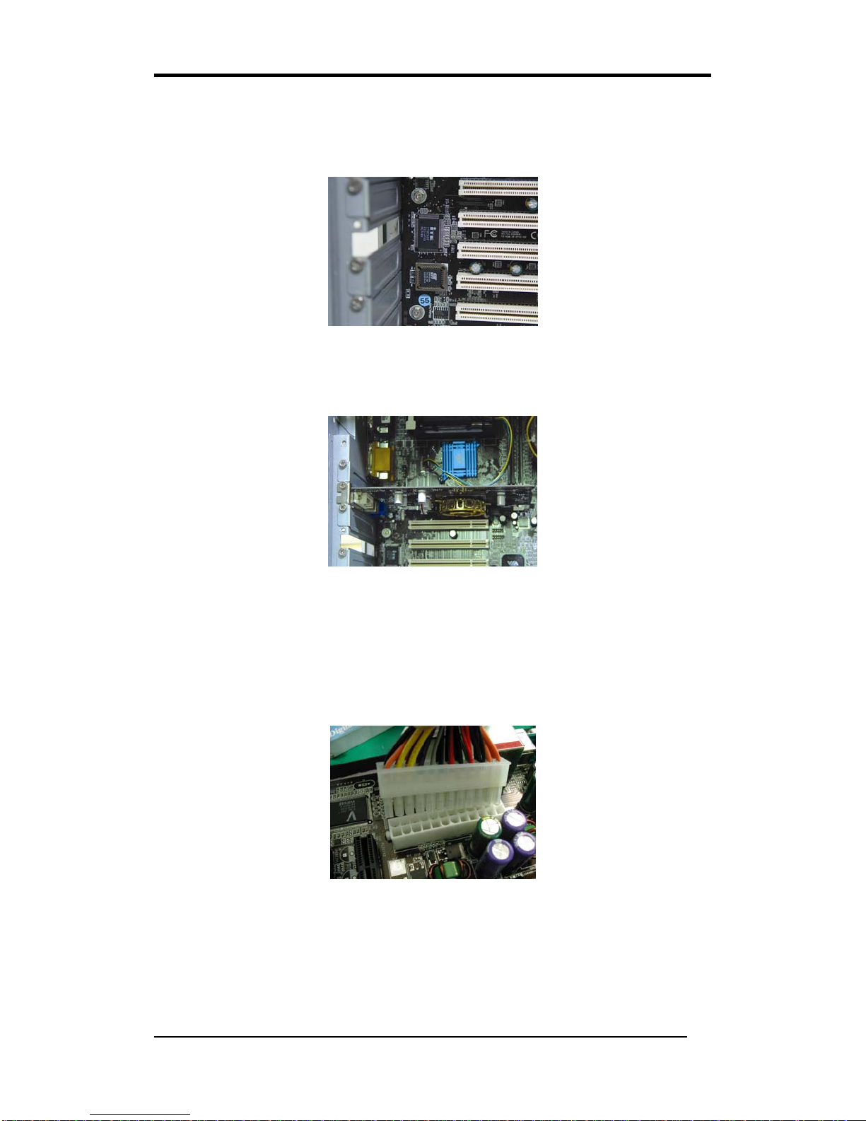
5. Mounting a Motherboard into a Chassis:
Use standoffs and screws to securely mount the motherboard. Install the standoffs
based on the mounting holes of you motherboard layout.
6.Adding an expansion card:
Align the card with the proper slot and fully seat the card. Secure with the retention
screw.
7. Connecting I/O ports and device connectors:
Plug the cable into the respective device port or connector as shown in the manual or
silkscreen printed on the motherboard.
8. Connecting the Power Supply Cables:
Plug in the 21- pin ATX power cable to the motherboard’s power connector and make
sure the cable is seated fully.
Chapter 2
9
2-2 Jumpers
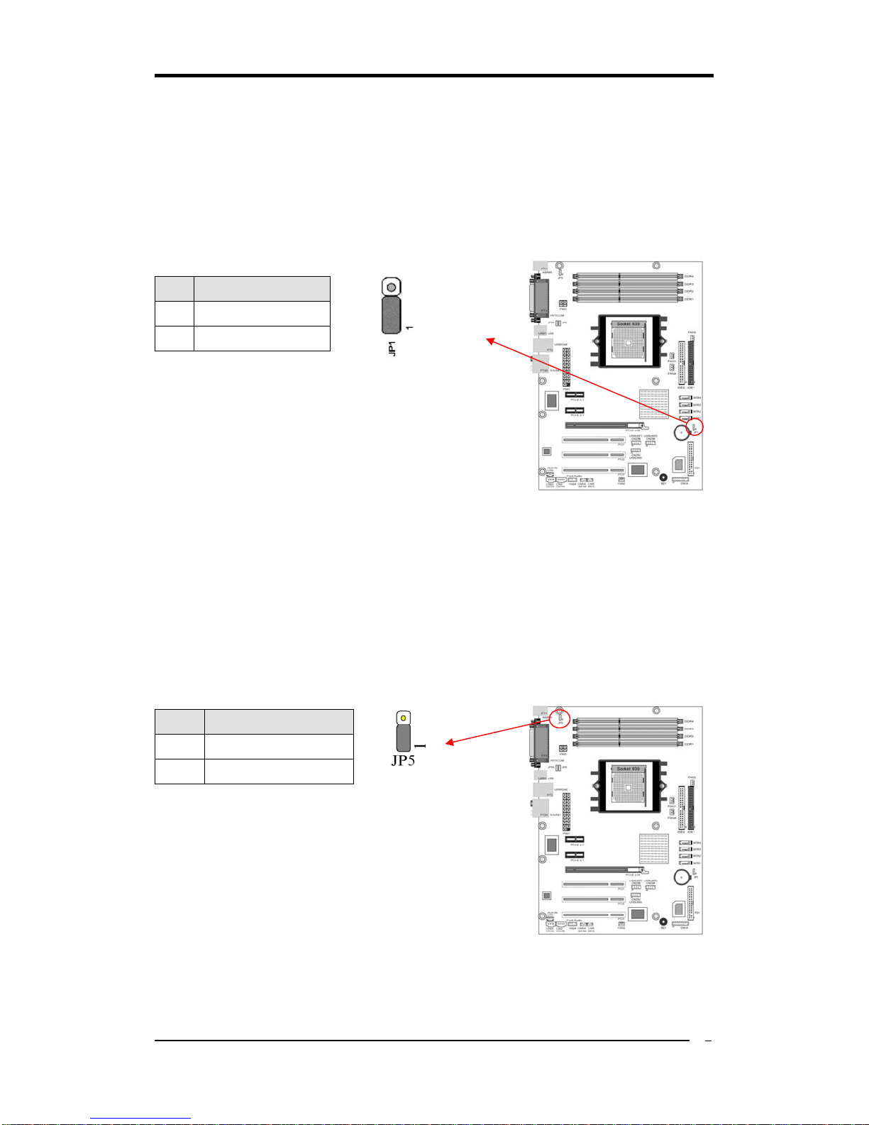
JP1 (CMOS Clear Jumper):
There is a CMOS RAM chip on board that has power
from external battery to retain the data and system
configuration. To clear the contents of the CMOS,
please follow the steps below.
1. Disconnect the system power supply from the
power source.
2. Set the jumper cap at location [2-3] for <5 seconds>, and then set it back to the
default position.
3. Connect the system's power and then start the system.
4. Enter BIOS's CMOS Setup Utility and choose Load Optimized Defaults. Type
[Y] and then press [Enter] to continue.
5. Set the system configuration in the Standard CMOS Setup menu.
JP5 (KB/MS Power On)
This motherboard can be turned on by the PS / 2
keyboard (hot key). To use this function, select a hot
key of your choice at the Hot Key Power ON option
under Wake Up Events in the BIOS's Power
Management Setup screen. You must also set this
jumper's cap to pins [2-3] to use this function.
Pin Definition
1-2 Normal (default)
2-3 Clear CMOS Data
Pin Definition
1-2 Disable
2-3 Enable

Chapter 2
10
JP6/6A (USB Power On)
A USB keyboard hot key or a USB mouse-click can
activate this motherboard. To use this function, select a
hot key of your choice at the USB Resume from S3
option under Wake Up Events in the BIOS's Power On
Management screen. You must also set this jumper's
cap to pins 2-3 to use this function.
2-3 Connectors
Rear Panel Connectors
1. PS/2 mouse port. The green 6-pin connector is used to connect your PS/2 mouse.
2. PS/2 keyboard port. The purple 6-pin connector is used to connect your PS/2
keyboard.
3. Parallel port. The 25-pin port is used to connect parallel devices such as a printer or
scanner.
4. Serial ports. The 9-pin ports are used to connect serial devices.
5. USB 2.0 ports. The 4-pin Universal Serial Bus (USB) ports are used to connect
USB 2.0 devices.
6. RJ-45 port. The port can be used to connect to a Local Area Network (LAN) via the
network devices.
7. Line-In port. The blue port is used to connect audio devices such as the CD or MP3
player. The port also serves as the Digital Optical Output.
Pin Definition
1-2 Disable
2-3 Enable
○
1
○
2
○
3
○
4○
5
○
6○
7
○
8○
9
○
10
○
11
○
12

Chapter 2
11
8. Line-Out port. The green port is used to connect audio devices such as headphones
or speakers.
9. Microphone port. The pink port is used to connect a microphone.
10. Side Speaker-Out port. The black port is used to connect side speakers in the
8-channel audio configuration
11. Rear Speaker-Out port. The gray port is used to connect rear speakers in the
4-channel, 6- channel or 8-channel configuration.
12. Center/Subwoofer port. The yellow port is used to connect the center/subwoofer
speakers in the 6-channel or 8-channel audio configuration.
Internal Connectors
IDE 1/2 (IDE Hard-Disk Connector):
This motherboard has a 32-bit Enhanced PCI IDE and Ultra ATA66/100/133
controller that provides PIO mode 0~4, Bus Master, and Ultra ATA66/100/133
function. This connector is used for connecting ATAPI devices.
IDE 1 only connects two IDE devices. (Primary Master/Slave)
IDE 2 only connects two IDE devices. (Secondary Master/Slave)

Chapter 2
12
FD1 (Floppy Connector):
This motherboard provides a standard floppy disk drive connector that supports 360K,
720K, 1.2M, 1.44M and 2.88M floppy disk types. It is connected to a floppy disk drive
using 34 pins.
SATA 1/2/3/4 (Serial ATA Connector):
This motherboard comes with 4 Serial ATA connectors that can be connected to the
ATA 1.5GB/S (VNF4) or ATA2 3.0GB/S (VNF4 Ultra). In addition, they possess the
hot-swap capability that will allow you change SATA drives without powering down
the system. They also support Nvidia RAID0/1/0+1 for optimizing your system.

Chapter 2
13
FAN1/2/3/4 (CPU/System/ Case Fan /Chip Fan Connectors):
This motherboard's hardware management is able to detect the CPU and system fan
speed in rpm (revolutions per minute). The wiring and plugging may vary depending
on the manufacturer. On standard fans, the red is positive (+12V), the black is ground,
and the yellow wire is the rotation signal. Connect a 3rd part north-bridge cooling fan to
FAN4.
CN23A/23B/23C (USB Connector for USB 4/5,6/7 and 8/9):
If you want to use a USB Keyboard, you must enable the USB keyboard support
function in the BIOS's Integrated Peripherals menu. This motherboard contains a USB
Host controller and a root hub with two connectors.
Chapter 2
14
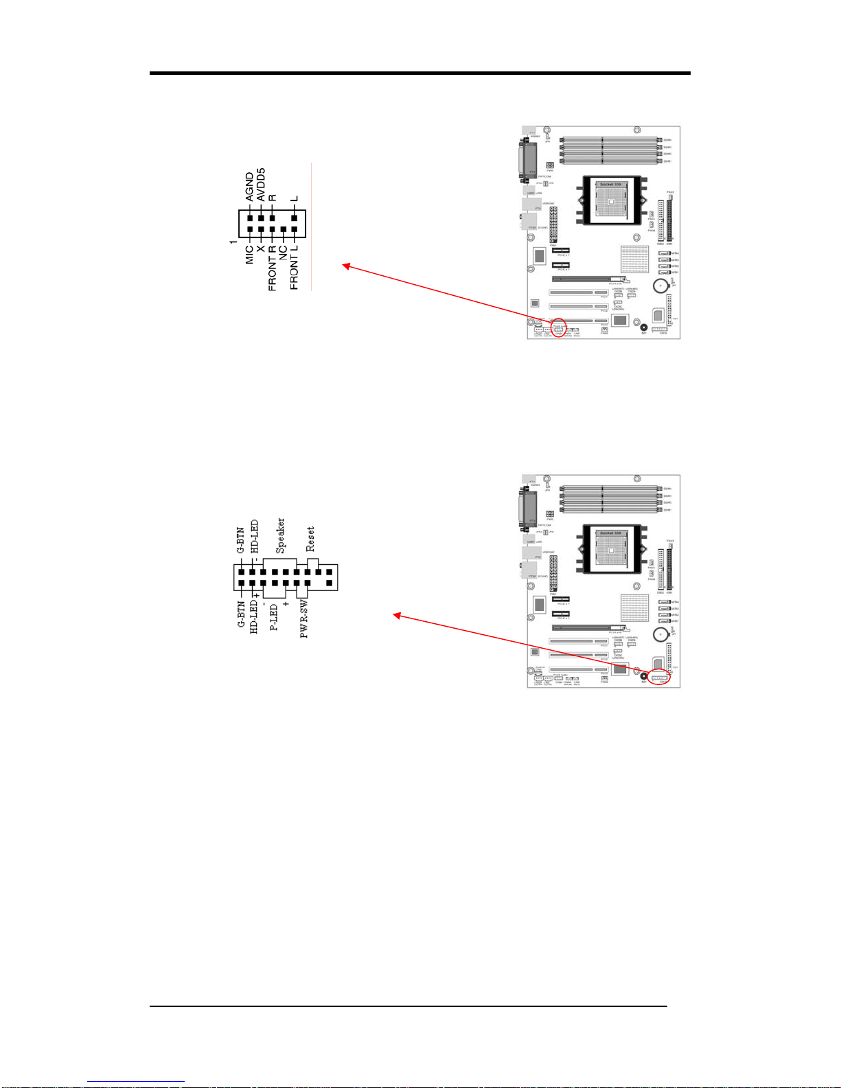
CN24(FrontAudioConnector):
This connector gives you the option of a front-panel
audio-jack cable to be plugged into a case supporting front panel audio.
Remove the two jumper caps at pins [5-6] and [9-10] then plug it into the (optional)
cable connector. Pins [5-6] and [9-10] are shorted (default) to enable back-panel audio.
CN1A (Front Panel Connector):
1. PWR-SW (Over-ride Power Button Connector):
The power button on the ATX chassis can be used as a normal power switch as well
as a device to activate theAdvanced Power Management Suspend mode. This is a
power-saving mode used for saving electricity when the computer is idle for long
periods of time. The Soft-OFF by PWR-BTTN function in BIOS's Power
Management Setup menu must be set to [Delay 4 Sec.] to activate this function.
When the Soft-OFF by PWR-BTTN function is enabled, pressing the power button
rapidly will switch the system to Suspend mode. Any occurrence of external
activities such as pressing any keys on the keyboard or moving the mouse will bring
the system back to Full-On. Pushing the button while in Full-On mode for more than
[4 seconds] will switch the system completely off. See Over-ride Power Button
Operation diagram.
Table of contents


