Revision 1.10, 04-Mar-2010 Page 6 of 24
www.austriamicrosystems.com
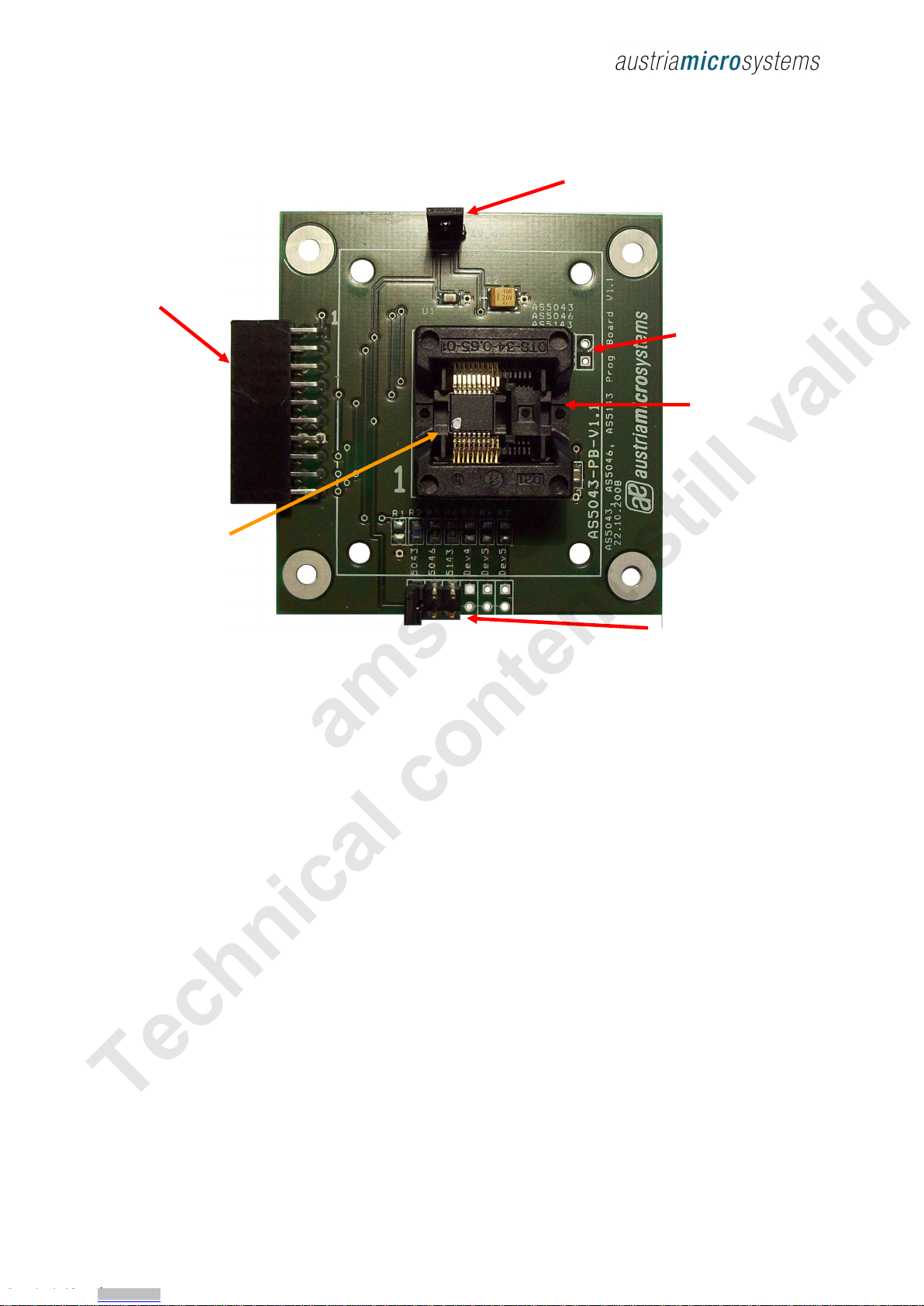
4.1 Programming the AS5040/AS5045/AS5140/AS5145
Programming AS5040/AS5140 enco ers requires the
AS5040-PB ZIF socket boar . This a apter is compatible
with AS5040, AS5140, AS5045 an AS5145.
Jumper J6 must be close for normal operation an
programming operation.
Figure 5: AS5040-PB Programming bo ard
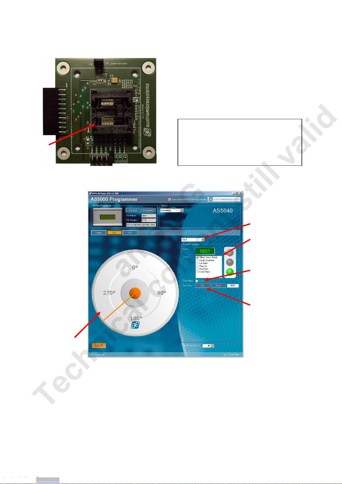
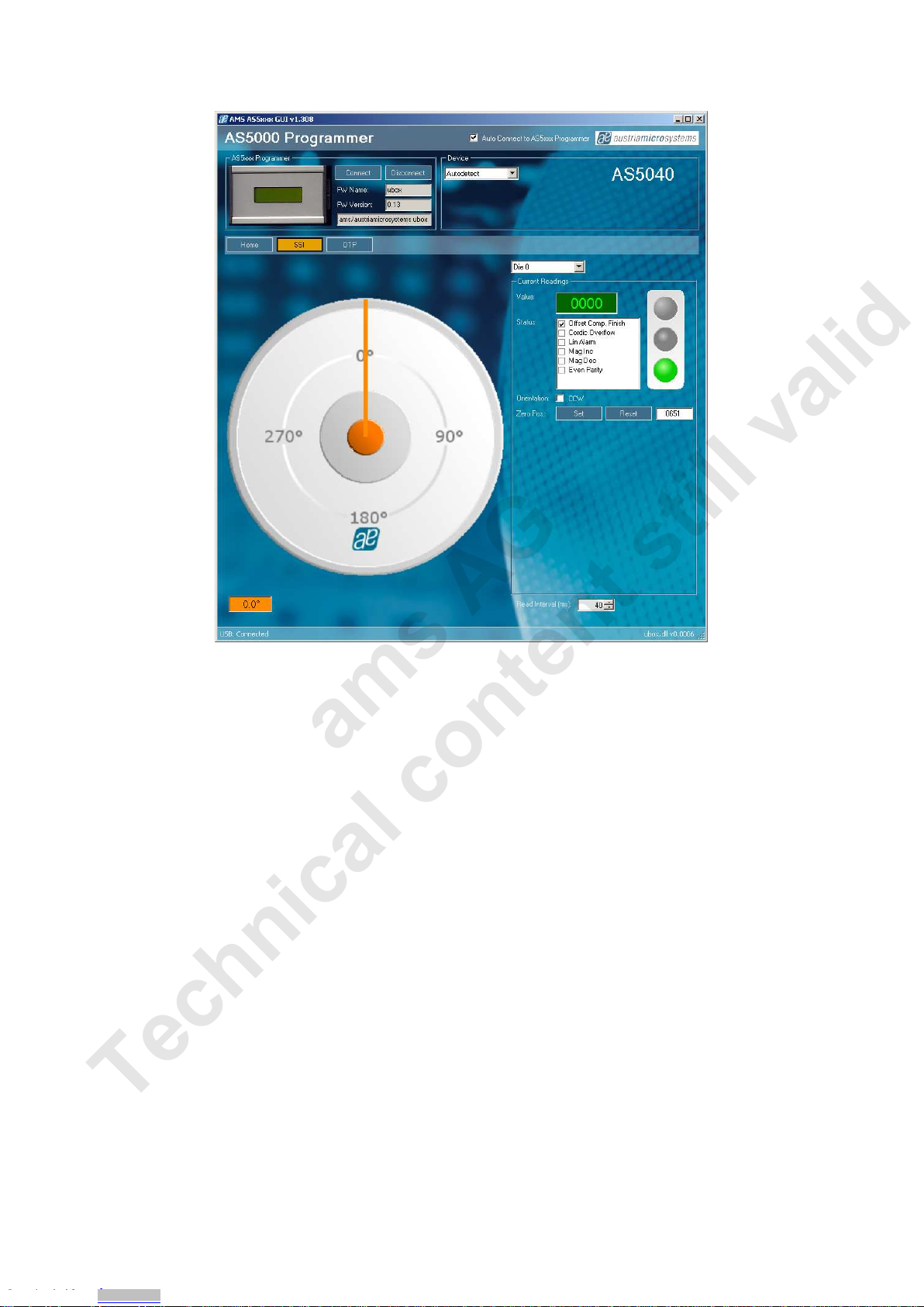
By selecting the SSI tab, information of the angular position an the status bits appear:
Figure 6: SS I tab with AS 5040 encoder in serted in AS5040-P B
-Die selection: This option is for ual ie AS52xx evices only. For AS50xx an AS51xx evices Die 0 ( efault)
must be selecte .
-Value fiel is the raw angle extracte from the SSI stream. The angle range is 0 (0°) to 1023 (359.6°)
-Status fiel isplays the status bits extracte from the SSI stream. Green light means that the airgap between
the magnet an enco er is correct. Orange light means the magnet is too close of too far.
-CCW checkbox is the angle irection. To invert the rotating irection, check CCW.
-Zero Position fiel : Set button writes the actual angle value into the Zero Position register of the enco er. This
programming is not permanent. The actual value will be 0 after zero position programming. To reset the zero
position register, or to set a new zero position, click on Reset first.
-Rea interval is the SSI stream rea out an refresh rate the GUI.
Device selection for auto etect:
-Jumper position 2: AS5040
-Jumper position 3: AS5045
-Jumper position 4: AS5140
-Jumper position 5: AS5145