BFit BFITW 1000 User manual

Water Heater Models
BFITW 1000
BFITW 1250
BFITW 1500
BFITW 2000
Model: ______________________________________________
Serial Number: ______________________________________________
Installation Date: ______________________________________________
Heating Contractor: __________________________________________
INSTALLATION, OPERATION,
AND MAINTENANCE MANUAL
Do not store or use gasoline or other
ammable vapors and liquids in the vicinity
of this or any other appliance.
WHAT TO DO IF YOU SMELL GAS
• Do not try to light any appliance.
• Do not touch any electrical switch; do
not use any phone in your building.
• Immediately call your gas supplier
from a neighbor’s phone. Follow the
gas supplier’s instrucons.
• If you cannot reach your gas supplier,
call the re department.
Installaon and service must be performed
by a qualied installer, service agency or the
gas supplier.
WARNING: If the information in these
instrucons is not followed exactly, a re
or explosion may result causing property
damage, personal injury or death.
COMMERCIAL C
ONDENSING
WATER HEATER
Save this manual for future reference.
PN: 108588-06 REV. 6
S
A
N
I
T
A
T
I
O
N
L
I
S
T
E
D
Bryan Steam, LLC www.bryanboilers.com
Phone: 765-473-6651 783 N. Chili Avenue, Peru, IN 46970 inquiry@bryansteam.com

2
Table of Contents
A. Local Codes 5
B. Warranty 5
C. Shipment Damage 5
J. Disclaimers and Local Codes 6
C. Clearances 16
D. Common Condensate pump/Sump 35

3
Table of Contents
C. Standard Piping Components 37
D. Scalding 38
E. Water Quality 39
B. Start the BFIT 57
E. Pump Control 61

4
Indicates an imminent hazardous situation which, if not avoided,
willresultin death, seriousinjuryorsubstantialpropertydamage.
Indicates a potentially hazardous situation which, if not avoided,
could result in death, serious injury, or substantial property
damage.
Indicatesapotentiallyhazardoussituation which,if not avoided,
may result in moderate or minor injury, or property damage.
Indicates special instructions on installation, operation, or
maintenance which are important but not related to personal
injury hazards.
CAUTIONCAUTION
NOTICENOTICE
!
!
!

5
A. Local Codes
1. This unit shall be installed in accordance with those
This unit must be installed and serviced by a
3.
product.
4.
this product to be installed by a Licensed Plumber
B. Warranty
1.
the installing contractor to ensure all controls are
Factory warranty does not apply to units improperly
installed or improperly operated.
3.
4.
levels listed in .
C. Shipment Damage
1.
carrier.
D. Connecng Gas Supply Line
1.
damage the gas train components on the appliance
E. Appliance Operaon
1.
Table 4
appliance
3.
water. Any appliance that has been under water
must be replaced. Water damage to the unit can
F. Gas Leakage (If you detect or smell gas...)
1. Do not try to light any appliance.
Do not touch any electrical switch; do not use any
phone in the building.
3.
4.
department.
G. Maintenance
1.
3. To prevent severe burns, allow the appliance to
H. Product Idencaon Label
1.

6
II(continued)
I. Factory Test and Inspecons
1.
J. Disclaimers and Local Codes
1.
to the National Fuel Gas Code, NFPA 54/ANSI
Z223.1, and/ or CSA B149.1 Natural Gas and
Propane Code. Where required by the authority
to the Standard for Controls and Safety Devices for
Automacally Fired Boilers, ANSI/ ASME CSD-1.
equipment can be hazardous and requires trained,
install, operate, service or repair any components
understand all requirements and procedures.
3.
product and must be retained by the person in
maintenance.
-
go to: www. P65Warnings.ca.gov.
!
the appliance.
!

7
-
corrosion. These water heaters are not
Informaon specic to the Dual Gas model can be found
in the appendices.
Specication BFITW Models
1000 1250 1500 2000
Fuel NG or LP NG or LP NG or LP NG or LP
Max. Water Temp. (°F)1210 210 210 210
Max. Working Pres. (psi) 160 160 160 160
Standard Safety Relief
Valve (psi) 150 150 150 150
Water Vol. (gal) 12 12 13.9 17.2
Heat Transfer Area (sq. ft.) 100 100 120 153
Approx. Shipping Weight (lb) 922 922 1217 1217
1Appliance will go into hard lockout if temperature exceeds 200 0F.
1000 200 1000 980 1188 98 97
1250 250 1250 1225 1485 98 97
1500 300 1500 1470 1782 98 97
2000 400 2000 1960 2376 98 96.9
Ratings shown are for installations at sea level and elevations up to 2000 ft. at minimum vent length.
For high altitude installations above 2000 ft. consult factory.

8
III(continued)
Dimensions
(in.)
BFITW Model
1000 1250 1500 2000
A 45-1/2 45-1/2 66-1/8 66-1/8
B 54 54 72-1/2 74-5/8
C 55-7/8 55-7/8 76-1/2 76-1/2
D 34-1/4 34-1/4 34-1/4 34-1/4
E 13-3/8 13-3/8 13-3/8 13-3/8
F 42-3/4 42-3/4 42-3/4 42-3/4
G 36-1/8 36-1/8 36-1/8 36-1/8
H 3 3 3-1/4 3-1/4
I 6-7/8 6-7/8 18-7/8 18-7/8
J 10-3/8 10-3/8 10-3/8 10-3/8
K 8-3/4 8-3/4 6-5/8 8-3/4
L 40-1/2 40-1/2 40-1/2 40-1/2
M 44-3/8 44-3/8 44-3/8 44-3/8
N 2-1/8 2-1/8 2-1/8 2-1/8
O 9-3/4 9-3/4 9-3/4 9-3/4
P 13-3/8 13-3/8 13-3/8 13-3/8
Q 6-1/8 6-1/8 6-1/8 6-1/8
R 11-1/8 11-1/8 11-1/8 11-1/8
S 23-1/4 23-1/4 23-1/4 23-1/4
T 32-1/8 32-1/8 32-1/8 32-1/8
Gas Inlet 1 1 1.25 1.25
Outlet Pipe 3 3 3 3
Inlet Pipe 2-1/2 2-1/2 2-1/2 2-1/2
Air Intake 8 8 8 8
Vent Outlet 8 8 8 8
Condensate
Drain 1 1 1 1
Drain Line 3/4 3/4 3/4 3/4
X-COG 18-3/8 18-3/8 18-3/8 18-3/8
Y-COG 17-3/4 17-3/4 21-5/8 25-5/8
Z-COG 21 21 22-5/8 20-3/4

9
III(continued)
G
F
(Z-COG)
(X-COG)
L
J
(Z-COG)
(Y-COG)
K
M
SUPPLY NOZZLE
RETURN NOZZLE
LIFTING LUGS
Q
T
P
S
R
O
N
1" CONDENSATE DRAIN
AIR SUPPLY
VENT
DRAIN
A
D
E
C
I
H
B
SUPPLY
NOZZLE
RETURN
NOZZLE
GAS TRAIN CONNECTION

10
1. Communicaon Interface (ConcertTM Control)
The BFIT series is equipped with the Concert Control
-
2. Main appliance control
3. Control box
-
ing purposes.
4. ON/OFF switch
5. Main gas valve
6. Blower
7. BluejetRBurner
Burner is mounted
8. Ignion electrode
-
9. Flame observaon port
10. Thermal fuse
0F,
11. High gas pressure switch
The high gas pressure switch monitors supply gas pressure
Table 31
12. Low gas pressure switch
The low gas pressure switch monitors supply gas pressure
Table 31
13. Outlet/Hot water connecon
Table 3
14. Water ow switch
Table
15. Gas supply line
the gas train assembly. See Table 31
pipe sizes.
16. Outlet/Cold water connecon
Table 3
17. Hot/outlet water temperature sensor
18. Cold/Inlet water temperature sensor
temperature rise.
19. Low water cut o probe and reset box
20. Temperature and pressure gauge
readings.
21. Temperature and pressure safety relief valve
-
22. Condensate drain trap
drain line.
23. Minimum combuson air proving switch
-
24. Blocked vent switch
vent piping.
25. Combuson air lter box
-
26. Exhaust vent connecon
Table 6
27. Heat Exchanger
316L Stainless Steel, Condensing, water tube type

11
IV(continued)
1
4
19
16
3
15
12
5
15
6
13
11
21
13
14
20
10
9
8
17
19

12
IV(continued)
26
25
22
18
2
23
27

13
A. Unpacking and Inspecon
1.
3.
4.
5.
6. The appliance can be moved to its permanent
7.
8.
NOTICENOTICE
-
B. Check Equipment
1.
shipment damage.
otherwise mishandled.
3.
slip with those actually received. In case there
carrier.
C. Installaon and Operaon Manual
1.
-
-
underwater must be replaced.
!

14
A. General
1.
Naonal Fuel Gas
Code, ANSI Z223.1/NFPA 54, and/or Natural Gas
and Propane Installaon Code, CAN/CSA B149.1.
Standard for
Controls and Safety Devices for Automacally Fired
Boilers, ANSI/ASME CSD-1.
Table 5
clearances may be reduced but should not be less
3.
4. Provide combustion and ventilation air in
5. The appliance should be located so as to minimize
Table 4
particular, avoid areas near chemical products
removers, cleaning solvents, and detergents. Avoid
dry wall dust etc.
6. This appliance must not be installed in a room
under negative pressure. An equipment room
a.
NOTICENOTICE
-
be cleaned and inspected daily to insure proper
inside the vent connector. Failure to apply the
-
-
-
maintenance can cause property damage, personal
!

15
B. Appliance Mounng
1.
in property damage.
3.
4.
5.
could accumulate around the appliance. The
components.
a. A 4 in. service pad or condensate sump is required
condensate sump.
b.
includes a level metal or wooden base capable
c.
Contaminants to Avoid:
(CFC’s)
Permanent wave solutions
Chlorinated waxes/cleaners
Chlorine-based swimming pool chemicals
Calcium chloride used for thawing
Sodium chloride used for water softening
Refrigerant leaks
Paint or varnish removers
Hydrochloric acid/muriatic acid
Cements and glues
Anti-static fabric softeners used in clothes dryers
Chlorine-type bleaches, detergents, and cleaning
solvents found in household laundry rooms.
Adhesives used to fasten building products and
other similar products
Excessive dust and dirt
Areas likely to have contaminants:
Dry cleaning/laundry areas and establishments
Swimming pools
Metal fabrication plants
Beauty shops
Refrigeration repair shops
Photo processing plants
Auto body shops
Plastic manufacturing plants
New building construction
Remodeling areas
Garages with workshops
VI(continued)

16
C. Clearances
1.
Table 5.
3. It is the installers responsibility to provide enough
D. Clearances (French)
1.
Installation dans une garde-robe : assurer un
E. Closet and Alcove installaon
1. Include ventilation air openings in closet
pipes.
3.
clearances.
4.
VI(continued)
1000 20 22 6 24 20
1250 20 22 6 24 20
1500 24 22 6 24 20
2000 24 22 6 24 20
NOTICENOTICE
installing the appliance with smaller than the
maintenance.
zero clearance.
temperatures. Follow the required clearances and
vent material.

17
A. General Venng Guidelines
1. Install vent system in accordance with Naonal
Fuel Gas Code, ANSI Z223.1/NFPA 54 or Natural
a.
3.
Table 10
manual may be acceptable. It is the responsibility
adapters and materials.
a. It is recommended to consult with venting
4. Enclose vent passing through occupied or
unoccupied spaces above the appliance with
5.
6. This appliance operates under conditions that
7.
8.
B. Venng Design Requirements
venting system can be designed by consulting
equivalent length method in this manual.
1. Engineered Venng Method
characteristics and required conditions, an
individual or common venting system can be
WARNINGWARNING
This appliance must not be installed in a room
An equipment room under negative pressure
Failure to install the appliance in accordance with
this manual can cause property damage, personal
!
a.
Table 9.
b. and Oranges are shown in
Table 34.
c.
d.
e. Manifolded venng
with the other appliances in the system. Common
2. Equivalent length method:
Table 6.
Table 18.
NOTICENOTICE
-
prohibited.
installing vent support, drainage, and pitch.
Do not exceed maximum vent/combustion
air system length.

18
C. Field Installaon
1.
3.
4. Plan venting system to avoid possible contact
with plumbing or electrical wires. Start at the vent
5.
a.
with primer and glued with cement. Follow all
primer and the cement.
6. Size and cut wall opening such that a minimal
VII(continued)
WARNINGWARNING
a stud wall, in closets, and through wall penetra-
-
prohibited.
!
BFIT
Model
Combustion Air Length Vent Length
Pipe Dia.
in. (mm)
Minimum
ft. (m)
Maximum
ft. (m)
Pipe Dia.
in. (mm)
Minimum
ft. (m)
Maximum
ft. (m)
1000 8 (200) 0 150 (45.7) 8 (200) 3 (0.9) 150 (45.7)
6 (160) 0 70 (21.3) 6 (160) 3 (0.9) 70 (21.3)
1250 8 (200) 0 150 (45.7) 8 (200) 3 (0.9) 150 (45.7)
6 (160) 0 50 (15.2) 6 (160) 3 (0.9) 50 (15.2)
1500 8 (200) 0 150 (45.7) 8 (200) 3 (0.9) 150 (45.7)
6 (160) 0 50 (15.2) 6 (160) 3 (0.9) 50 (15.2)
2000 8 (200) 0 100 (30.5) 8 (200) 3 (0.9) 100 (30.5)
2500 10 (250) 0 150 (45.7) 10 (250) 3 (0.9) 150 (45.7)
3000 10 (250) 0 150 (45.7) 10 (250) 3 (0.9) 150 (45.7)
3500 12 (315) 0 150 (45.7) 12 (315) 3 (0.9) 150 (45.7)
4000 12 (315) 0 150 (45.7) 12 (315) 3 (0.9) 150 (45.7)
NOTE:
Contact factory for assistance on maximum vent length applications.
This table applies to all listed vent/combustion air system options.

19
VII(continued)
Component
Combuson Air Vent
Equivalent
Length Per
Piece
xQuantity =
Subtotal
Equivalent
Length
Equivalent
Length
Per Piece
xQuantity =
Subtotal
Equivalent
Length
Straight Pipe x = A x = D
90° Elbow x = B x = E
45° Elbow x = C x = F
Combustion Air Total
Equivalent Length =Vent Total
Equivalent Length =
Notes:
1. Total equivalent length cannot exceed maximum equivalent length shown in Table 6.
2. Combustion air and vent terminations do not count towards total equivalent length.
Diameter 6 in. (160 mm) 8 in. (200 mm) 10 in. (250 mm) 12 in. (315 mm)
90°Elbow 7 ft. (2.1 m) 11 ft. (3.4 m) 14 ft. (4.3 m) 18 ft. (5.5 m)
45° Elbow 3 ft. (0.9 m) 4 ft. (1.2 m) 5 ft. (1.5 m) 7 ft. (2.1 m)
At Maximum Input Rate At Minimum Input Rate
BFIT
Model
Vent
Dia. (In.)
Flue Gas Flow,
ACFM @ 35%
Excess Air, 180 0F
Combustion Air,
SCFM @ 35%
Excess Air, 60 0F
Flue Gas Flow,
ACFM @ 35%
Excess Air, 180 0F
Combustion Air,
SCFM @ 35%
Excess Air, 60 0F
1000
8
282 212 56 42
1250 352 265 70 53
1500 423 318 84 63
2000 564 424 113 85
2500 10 705 531 141 106
3000 846 637 169 127
3500 12 987 743 197 148
4000 1129 849 225 170
Note: Flow rates are based on the combustion of natural gas.
Make Material Model
Heat Fab Stainless Steel Saf-T Vent EZ Seal*
Z-Flex (Nova Flex Group) Stainless Steel/
Polypropylene Z-Vent/Z-DENS
DuraVent Polypropylene PolyPro Single Wall Rigid
Centrotherm Polypropylene InnoFlue SW Rigid
materials or manufacturers.

20
VII(continued)
Stainless Steel to CPVC Heat Fab to Z-Vent
Vent Diameter (in.) Thermal Solutions Part # Z-Flex Part #
8 109510-01 2SVSHF08
10 109510-02 2SVSHF10
12 109510-03 2SVSHF12
BFIT
Model
Ve n t
Diameter (in.)
Centrotherm Part #
(Innoue PP System)
Z-Flex Part #
(Z-DENS PP Systems)
1000
1250
1500
2000
8 ISSA0808 2ZDAHF8
2500
3000 10 ISSA1010 -
3500
4000 12 ISSA1212 -
BFIT
Model
Ve n t
Diameter (in.) Style Heat Fab Part #
Saf-T Vent
Z-Flex Part #
Z-Vent
1000
1250
1500
2000
8
Tee 9890TEE 2SVST08
Elbow 9814TERM 2SVEE0890
Straight 9892 2SVSTPX08
2500
3000 10
Tee 91090TEE 2SVST10
Elbow 91014TERM 2SVEE1090
Straight 91092 2SVSTPX10
3500
4000 12
Tee 91290TEE 2SVST12
Elbow 91214TERM 2SVEE1290
Straight 91292 2SVSTPX12
BFIT
Model
Ve n t
Diameter (in.) Style Centrotherm Part #
InnoFlue
Z-Flex Part #
Z-DENS
1000
1250
1500
2000
8
Tee ISTT0820 2ZDTT8
Elbow - -
Straight ISEP086 -
2500
3000 10
Tee ISTT1020 -
Elbow - -
Straight ISEP106 -
3500
4000 12
Tee ISTT1220 -
Elbow - -
Straight ISEP126 -
This manual suits for next models
3
Table of contents
Popular Water Heater manuals by other brands

John Wood
John Wood 300 Series Installation and operating manual

Nibe
Nibe VPB 500 UK Installation and maintenance instructions

Electrolux
Electrolux EYL85066WE user manual

Vaillant
Vaillant electronicVED lite operating instructions
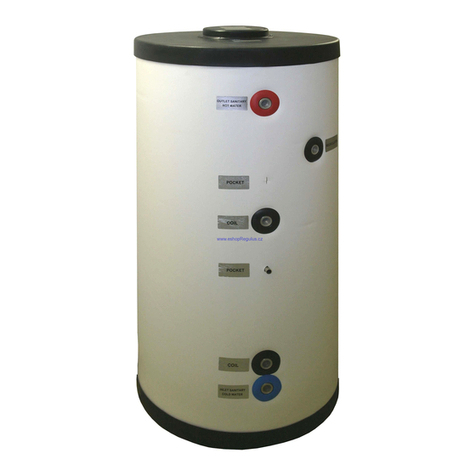
Aqua-Hot
Aqua-Hot AHE-100-02S -12 VDC owner's manual

CTC Union
CTC Union EcoZenith i360 Series Installation and maintenance manual
Eccotemp
Eccotemp i12 Series Use and care guide
Nibe
Nibe PUB2 Series Installation and maintenance instructions

Viessmann
Viessmann Vitocell 100 installation instructions

American Water Heater
American Water Heater 52 Series instruction manual
Webasto
Webasto D5W Z manual
BOCK
BOCK EzFit EZ 75-76 instruction manual
