BGE BGO30B User manual

BGO30B/50B/60B/80B; BGO70A/100A
Instruction Manual
Direct and Indirect-fired
Diesel/Kerosene Heaters
BGO-30B Indirect-fired
BGO-50B Indirect-fired
BGO-60B Indirect-fired
BGO-80B Indirect-fired
BGO-70A Direct-fired
BGO-100A Direct-fired
Introduction
Thank you for choosing a BGE product. Read this manual carefully before using the unit and save it for
future reference.
Disclaimer
BGE reserves the right to make alterations to specifications, quantities, dimensions etc. for production
or other reasons, subsequent to publication.
While we believe the information is accurate and complete, we make no warranty or representation for
any particular purposes. The information is offered in good faith and with the understanding that any
use of the units or accessories in breach of the directions and warnings in this document is at the sole
discretion and risk of the user.
Disposal guidelines (EU)
Do not dispose of this product with general household waste. This product must be disposed according
to the laws governing Waste Electrical and Electronic Equipment. If required, contact your local
authorities for information regarding the available disposal facilities.
1. General Safety Rules
READ INSTRUCTIONS CAREFULLY. READ AND FOLLOW ALL INSTRUCTIONS. PLACE
INSTRUCTIONS IN A SAFE PLACE FOR FUTURE REFERENCE. DO NOT ALLOW ANYONE
WHO HAS NOT READ THESE INSTRUCTIONS TO ASSEMBLE, LIGHT, ADJUST OR OPERATE
THE HEATER.
IF THE INFORMATION IN THIS MANUAL IS NOT FOLLOWED EXACTLY, A FIRE OR
EXPLOSION MAY RESULT CAUSING PROPERTY DAMAGE, PERSONAL INJURY OR LOSS
OF LIFE.
SERVICE MUST BE PERFORMED BY A QUALIFIED SERVICE AGENCY.
UNVENTED PORTABLE HEATERS USE AIR (OXYGEN) FROM THE AREA IN WHICH IT IS
USED. ADEQUATE COMBUSTION AND VENTILATION AIR MUST BE PROVIDED. REFER TO
INSTRUCTIONS. WARNING
DO NOT STORE OR USE GASOLINE OR OTHER FLAMMABLE VAPORS AND LIQUIDS IN
THE VICINITY OF THIS OR ANY OTHER APPLIANCE.
WARNING
FIRE, BURN, INHALATION, AND EXPLOSION HAZARD. KEEP SOLID COMBUSTIBLES, SUCH
AS BUILDING MATERIALS, PAPER OR CARDBOARD, A SAFE DISTANCE AWAY FROM THE
HEATER AS RECOMMENDED BY THE INSTRUCTIONS. NEVER USE THE HEATER IN
SPACES WHICH DO OR MAY CONTAIN VOLATILE OR AIRBORNE COMBUSTIBLES, OR
PRODUCTS SUCH AS GASOLINE, SOLVENTS, PAINT THINNER, DUST PARTICLES OR
UNKNOWN CHEMICALS.
WARNING
DIRECT-FIRED HEATERS MAY CAUSE CARBON MONOXIDE (CO) POISONING WHEN
INCORRECTLY USED, E.G INDOORS WITHOUT ADEQUATE AIR CIRCULATION, OR IF NOT
PROPERLY WORKING. CO POISONING MAY LEAD TO DEATH.
GENERAL HAZARD WARNING
FAILURE TO COMPLY WITH THE PRECAUTIONS AND INSTRUCTIONS PROVIDED WITH
THIS HEATER, CAN RESULT IN DEATH, SERIOUS BODILY INJURY AND PROPERTY LOSS
OR DAMAGE FROM HAZARDS OF FIRE, EXPLOSION, BURN, ASPHYXIATION, CARBON
MONOXIDE POISONING, AND/OR ELECTRICAL SHOCK. ONLY PERSONS WHO CAN
UNDERSTAND AND FOLLOW THE INSTRUCTIONS SHOULD USE OR SERVICE THIS
HEATER. IF YOU NEED ASSISTANCE OR HEATER INFORMATION SUCH AS AN
INSTRUCTIONS MANUAL, LABELS, ETC. CONTACT THE MANUFACTURER.
WARNING
NOT FOR HOME OR RECREATIONAL VEHICLE USE
WARNING
YOUR SAFETY IS IMPORTANT TO YOU AND TO OTHERS,
SO PLEASE READ THESE INSTRUCTIONS BEFORE YOU OPERATE THIS HEATER
THE ELECTRICAL SYSTEM TO WHICH THE APPLIANCE IS CONNECTED MUST COMPLY
WITH CURRENT LEGISLATION. INSTALLATION REQUIRES A RESIDUAL CURRENT
CIRCUIT BREAKER (RCCB) IN THE MAIN ELECTRICAL DISTRIBUTION BOARD.
UNPLUG THE APPLIANCE BEFORE PERFORMING ANY MAINTENANCE OPERATIONS.
ALWAYS CHECK THE POWER CABLE BEFORE USING THE APPLIANCE. IT MUST NOT
BE BENT, TAUT, STRETCHED, CRUSHED OR ANY WAY DAMAGED.
THE POWER CABLE MUST BE REPLACED BY QUALIFIED PERSONNEL ONLY. USE AN
ORIGINAL POWER CABLE ONLY WITH A 3-PIN APPROVED PLUG.
THE FRONT OUTLET IS VERY HOT DURING OPERATION. DO NOT TOUCH! BURN
DANGER.
2. Product Description
Diesel or Kerosene direct-fired mobile/portable space heater with open combustion chamber and
indirect fired mobile/portable space heater with close combustion chamber
3. Technical Specifications
Model
BGO-30B
BGO-50B
BGO-60B
BGO-80B
BGO-70A
BGO-100A
Heat Input* [kW]
[Hrs]
30
50
60
80
70
100
Air Flow Rating
[m³/h]
780
2000
2000
2000
1300
1300
Fuel Type
Diesel -
Kerosene
Diesel -
Kerosene
Diesel -
Kerosene
Diesel -
Kerosene
Diesel -
Kerosene
Diesel -
Kerosene
Fuel consumption
[kg/h]
2.4
3.8
4.7
6.3
5.4
7.9
Fuel Nozzle size
0.60 gph-60°
1.00 gph-80°
1.0 gph-80°
1.35 gph-60°
1.35 gph-60°
1.75 gph-60°
Voltage [V]
220-240V
50Hz
220-240V
50Hz
220-240V
50Hz
220-240V
50Hz
220-240V
50Hz
220-240V
50Hz
Electrical Power
(Motor )
250W
750W
750W
750W
430W
430W
Pump Pressure
Setting [bar]
10.0
10.5
11.5
10.0
10.5
10.0
Current Rating [A]
1.5
3.2
3.2
3.3
2.6
2.6
Fuse Rating
T3.15A
T3.15A
T3.15A
T3.15A
T3.15A
T3.15A
Air collar setting
[notch]
3
8
9
12
7
6
Efficiency* [%]
83
87
87
82
-
-
Dimensions
Net Weight (kg)
34.4
59
59
59
40.8
40.8
Length (mm)
1110
1370
1370
1370
1215
1215
Width (mm)
490
560
560
560
580
580
Height (mm)
750
995
995
995
705
705
Tank Capacity (l)
56
69
69
69
69
69
Operating range (h)
~20
~14
~12
~9
~10
~7
Standard
Accessories
Fuel gauge
yes
yes
yes
yes
yes
yes
Handle
1
1
1
1
1
1
Ambient thermostat
built-in
built-in
built-in
built-in
built-in
built-in
Malfunction
detection signal
built-in
built-in
built-in
built-in
built-in
built-in
*Based on dedicated setting for standard condition (atmospheric pressure 1020 kPa and Temperature 20 °C).
4. Assembling Instructions
Extract the heater from its carton. If the unit is anyhow damaged, do not use it and contact your dealer.

The following accessories are supplied in the shipping carton.
Fig.1
To assemble the heater, proceed as follows (see Fig. 1):
1、Insert the wheel shaft K to the corresponding hole of feet pipe B,insert the cotter J to the
corresponding holes; slide the wheel I over the wheel shaft K put plain washer H to the two sides of
shaft,,screw the nut G to fix the wheel on the shaft.
2、Put the heater body on the feet pipe assembly, make sure the 4 holes of handle A point towards
the corresponding 4 holes on the feet pipe respectively.
3、Using the screw F ,spring washer E, plain washer D and nut C to fix the feet pipe assembly and
handle to the tank.
5. Installation Instructions
Position the heater on a flat, level, non-flammable, solid surface.
The exhaust gases are very harmful for people and animals when released in a closed
space without ventilation.
Indirect-fired heaters while used in indoor installation, must be connected to an exhaust
pipe to vent the products of combustion outside. To maintain an adequate Oxygen rate,
a minimum of 80 m3/h airflow from outside must be ensured.
Direct-fired heaters are intended for use in outdoor open areas or in indoor well
ventilated areas. For indoor use, provide permanent ventilation openings of at least 25
cm²/kW, equally distributed between floor and high level, with a minimum of 250 cm².
BGO-70A
BGO-100A
Minimum Opening Size
1750 cm²
2100 cm²
Only install the heater in normal upright position.
Do not place the heater near walls, corners or low ceilings.
Do not place the heater below a socket outlet.
Do not place the heater on moving vehicles or where it can tip over.
Keep the heater away from flammable, combustible, explosive or corrosive materials.
Keep the heater away from curtains or similar materials that could block the air inlet and
outlet.
Never block or restrict the air inlet and outlet for any reason.
Keep the power cable away from heat sources, sharp edges, cutting and moving parts.
Do not expose directly to the weather or to excessive humidity.
Do not place the heater in the immediate surroundings of a bath, shower or swimming
pool.
Pos.
Description
Qty
A
Handle
1
B
Feet pipe
1
C
Nut M5
10or12
D
Plain washer
10or12
E
Spring washer
6or8
F
Screw
10or12
G
Nut M12
2
H
Plain washer ø12
2
I
Wheel
2
J
Cotter
2
K
Wheel shaft
1
Follow general and special fire safety regulations in force in all fields of applications. In
any case ensure the following minimum safety clearances from materials or objects in
the surroundings of the heater:
Side: 1 m
Air inlet side: 1 m
Top: 1.5 m
Hot air outlet side: 3 m
Floor: 0 m
Floors and ceilings must be made of fireproof materials in the place where the heater is
operated.
Do not connect direct-fired heaters to air ducts.
6. Instructions for Use
6.1. Start-up
Fill tank with clean fuel. Only use Diesel or Kerosene.
The fuel gauge on top of the tank allows to check fuel
level
Connect the power cord plug to a AC220V-240V 50
Hz earthed electrical supply system.
Earthing is mandatory.
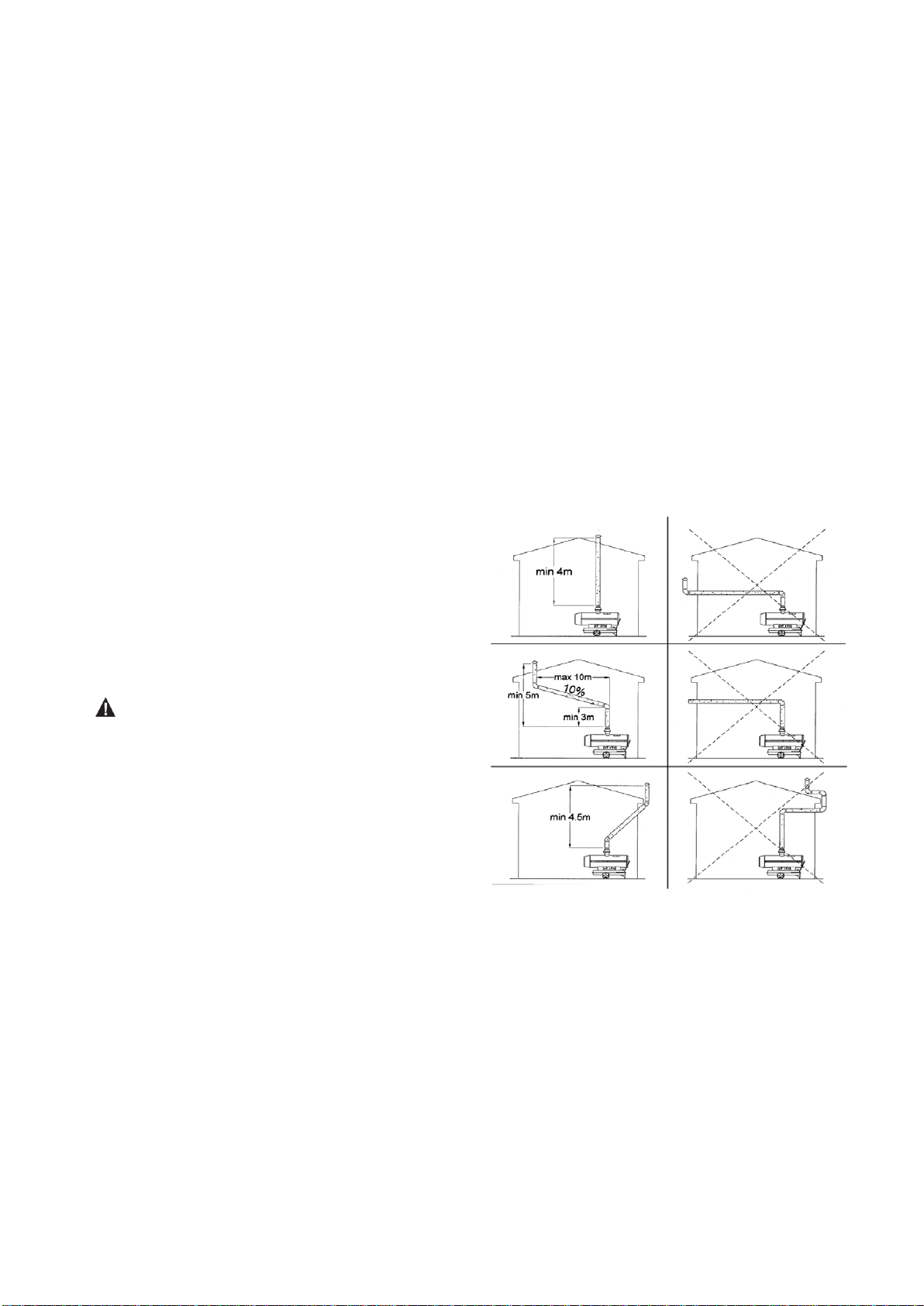
For indirect fired heaters: connect the heater
to a chimney or to an exhaust duct. To get a
proper draught in the chimney the exhaust gas
path must rise. Avoid any elbows and bends
in the first part of the exhaust ducts for at least
3 m.
When complete “start-up” above, the left display window shows “--”, the right display window shows
ambient temperature value.
Push the power switch to “on” position.
The default temperature setting is 20℃, be showed on the left display window.
If the ambient temperature is lower than default temperature, after waiting for 12 seconds per-
ventilation, the heater starts.
If the ambient temperature is higher than default temperature, turn thermostat control knob to
desired temperature, after waiting for 7 seconds pre-ventilation, the heater starts.
ABNORMAL OPERATION: in case of malfunction (flame failure, reduced air flow, bad combustion,
etc.) the heater stops, the LOCK-OUT MODE code will be showed on the display window-see
troubleshooting.

6.2. Manual reset/restart
If the heater is in lock-out mode, check and remove the cause of lock-out before restarting the heater.
To reset, turn the ON/OFF switch to 0 and then (afters 30 sec) again to I. In case of repeated
malfunction, call technical service. Turning the thermostat control knob will NOT reset the heater.
6.3. Shut-down
Move switch to "OFF" (O) position. The post-ventilation phase will cool down the combustion chamber
for 90 seconds. Unplug the unit when not used for a long time.
Never disconnect the heater from mains to stop it while in operation. Always allow the
cooling sequence to be completed, otherwise the residual heat could damage internal
components.
Do not cover the heater. Do not block the air inlet and outlet.
The heater outlet is very hot during operation and after use. Do not touch! Use personal
protecting equipment if needed.
Children should be supervised to ensure that they do not play with the appliance.
The appliance is not intended for use by persons (including children) with reduced
physical, sensory or mental capabilities, or lack of experience and knowledge.
Unplug the heater before moving it. Never pull the cable to unplug or move the unit.
Do not leave the heater unattended when in use.
Never use the appliance with wet hands or when either the heater or the power cable is
wet.
If the supply cable is damaged, it must be replaced by the manufacturer, by a service
agent or a similar qualified person.
7. Cleaning, Maintenance and Storage
Regularly wipe the enclosure using a soft sponge or cloth. For very dirty parts, use a sponge wetted
with lukewarm water and a mild detergent, then dry using a clean cloth.
Keep air inlet and fan free from dust and dirt. To clean inner parts, gently blow compressed air through
air inlet.
Regularly inspect the power cable: if worn, cracked or damaged have it replaced by technical service.
Before storing the heater, make sure it is perfectly cool and dry. Cover the unit with a plastic bag, put it
in its packing box and store it in a dry, ventilated place.
Before starting any maintenance task, shut down, unplug and let the heater cool down
for at least 15 minutes.
Do not attempt any electrical repair yourself. If the heater needs service or repair,
contact a qualified technician.
Do not use a faulty unit unless a qualified technician has inspected and repaired it.
When cleaning, make sure that water does not enter the unit.
Do not open the enclosure to clean the inner parts. Do not spray water into the heater.
Never use solvents, gasoline, toluene and similar aggressive chemicals to clean the
heater.
The following checks BY QUALIFIED PERSONNEL ONLY are recommended before every
seasonal use:
Fuel Filters

Clean fuel filters by unscrewing the filter tray (clockwise) Remove the filter cartridge and wash it with
petrol or replace it if necessary. Check seal O-ring and replace it if necessary. Reassemble the tray
(Fig.2). The fuel filter installed on the gear pump should be cleaned or replaced if necessary by
unscrewing cap H (see Fig. 6)
Fig. 2
Extract the burner head(Fig.3)
Fig.3
Whirl disc
Clean the whirl disc (Fig.3) using a brush and then blow compressed air on it. To get good
combustion the air flow openings in the whirl disc should be perfectly clean and free.
Nozzle
Carefully unscrew nozzle from nozzle fitting. Blow compressed air through nozzle orifice to free it from
dirt. Replace nozzle if necessary.
Ignition Electrodes
Clean, adjust and if necessary replace ignition electrode. For electrode gaps see Fig. 4-5 (dimensions
in mm).
Fig.4
Filter tray
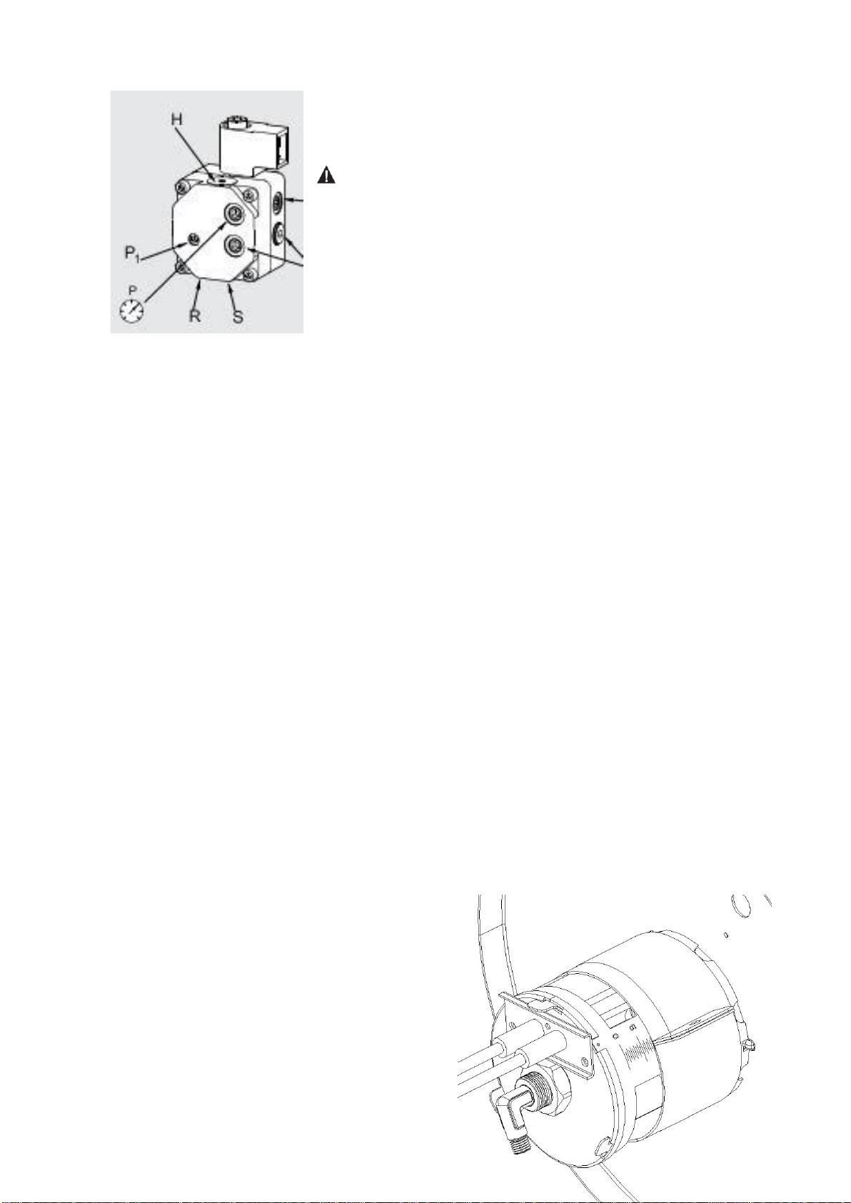
Fig.5
Fuel pump pressure adjustment (Fig. 6)
The fuel pressure is factory set and must be checked
and adjusted by qualified technicians only. Tampering
with the unit may be dangerous.
Remove pressure gauge cap (P). Connect a pressure gauge on
the pressure measuring port on pump. Start heater and read fuel
pressure value. If necessary adjust pressure to the correct value
turning the adjusting screw (P1) clockwise to increase,
anticlockwise to decrease the pressure:
Fig.6
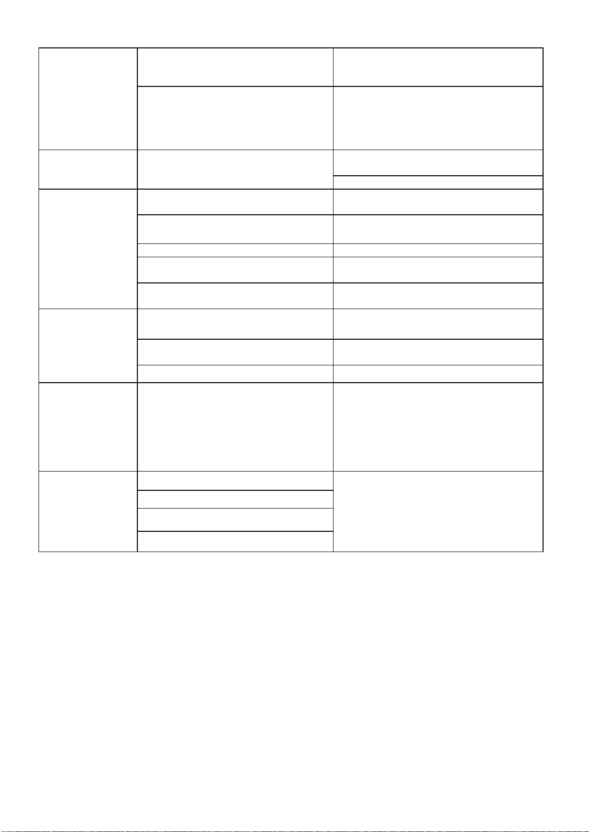
Air collar adjustment (Fig. 7)
The air collar position is factory set and must be checked and adjusted by qualified technicians
only. Tampering with the unit may be dangerous.
HIGH ALTITUDE ISTALLATION: Due to lower oxygen
rate with reference to high altitude installation on sea
level, it may be necessary to increase air rate by
opening the air collar (Fig. 7), or to reduce the setting
pressure on fuel pump (Fig. 6). This setting
adjustment can be necessary to prevent excessive
smoke emission due to lack of Oxygen.
Model
Pump Pressure (bar)
BGO-30B
10.0
BGO-50B
10.5
BGO-60B
11.5
BGO-80B
10.0
BGO-70A
BGO-100A
10.5
10.0

Fig.7
Electrical
Inspect cables, electrical parts and connections.
8. Wiring Diagram
9. Troubleshooting
PROBLEM
CAUSE
REMEDY
Motor does not
start
E1 displayed on
No power or low voltage
Check power line and voltage
Check fuse and replace if necessary
Faulty or damaged power cord
Check and replace if needed
the screen
Faulty motor/capacitor
Check and if necessary replace
Lock-out of appliance due to previous
overheating
Detect the cause of overheating
Shut the appliance down
Check air inlet and outlet
Wait some minutes and restart the
appliance
E2 displayed on
the screen
The temperature probe is faulted or
the connector for temperature probe is
loosen
Check and replace if the temperature
probe if needed
Check and replace the PCB if needed
Motor runs, but the
heater does not
ignite and locks
out after a short
time
E1 displayed on
the screen
Empty fuel tank, dirty or wrong fuel
Remove wrong or dirty fuel
Fill the tank with clean Diesel or kerosene
Ignition fault, dirty or incorrect
electrods position
Check and clean electrods
Fuel filter clogged
Clean or replace fuel filter
Burner nozzle clogged
Clean nozzle blowing compressed air,
replace if necessary
Fuel viscosity increased at low
temperature
Mix Diesel with 10-20% kerosene
Heater starts but
combustion is not
good
Insufficient airflow into combustion
chamber
Check air inlet, fan, motor and air collar
position, adjust it if necessary.
Wrong fuel pressure
Check fuel pressure, adjust it if needed
Leaks in fuel line
Check and fix fuel leaks
Heater stops
during operation
Ambient
temperature
displayed on the
screen
The room temperature set on room
thermostat has been reached
Normal operation
To start turn the temperature control knob
clockwise on a higher setting
Heater stops
during operation
E1 displayed on
the screen
Flame failure
Check and remove the cause(s) of
malfunction
To reset, turn On/Off switch to 0 and then
to I
Call technical service if the problem
persists
Bad combustion
Reduced airflow
Overheating
NINGBO BAOGONG ELECTRICAL APPLIANCE CO.,LTD.
Add: FuHai Industrial Zone, Cixi Nongbo city, China
PC.: 315332
Tel:+860574-63682508 63682208 63682210 63682210
Fax:+80-574-63682517
E-mail:linda@baogon.com
Http://www.baogon.com
BGE reserves the right to make alterations to specifications, quantities, etc., for production or other reasons, subsequent to publication.
©BGE. 2015
This manual suits for next models
5
Table of contents
Other BGE Heater manuals

Popular Heater manuals by other brands

Frico
Frico AGS5500 Original instructions

Pinnacle
Pinnacle REMINGTON REM-16-TTC-O User's manual & operating instructions

Dimplex
Dimplex Apollo APL100 Installation and operation maintenance

Herschel
Herschel IR360 Installation & operating instructions

Stover
Stover R 272 C datasheet

nootka saunas
nootka saunas BARREL SAUNA Setup instructions


