nootka saunas BARREL SAUNA Manual

BARREL SAUNA
HEATER SETUP INSTRUCTIONS
SECTIONS
1 – RUNNING ELECTRICAL TO THE SAUNA (APPROX. TIME: DEPENDS ON SETUP)
2 - WIRING THE SAUNA HEATER (APPROX. TIME: 1.5 – 2 HOURS)
3 - TROUBLESHOOTING
4 - HOMECRAFT HEATER MANUAL
AT T EN TI ON :( (
!""#$"$%&'(%)"#*('(+,#-.'#&/$#0)1+)#210$#%.24"$&$5#36#)#%$'78$5#$"$%&'(%()+9##
:/$'$#)+6#;..&<)#=)1+)0>#(+0&'1%7.+0#)+5#&/$#/$)&$'#2)+1-)%&1'$'>0#(+0&'1%7.+0#%.+&')5(%&#$)%/#.&/$'?#
5$-$'#&.#&/$#2)+1-)%&1'$'>0#(+0&'1%7.+09#
!0#4$'#@=!#@AA9A#;.9#BCDEAFBG?#0$%7.+#B9A#)+5#0$%7.+#G9B9H?#“factory)built)sauna)rooms)where)the)
necessary)wiring)and)heater)installa6on)is)done)in)the)field”,#'$I1('$#&/$#/$)&$'#)00$23"6#&.#%)''6#)#@=!#
@AA9A#;.9#BCDEAFBG?#31&#&/$#'..2#(&0$"-#(0#$J$24&#-'.2#&/$#5('$%7K$9#L/$#M.2$%')N#M$)&$'0#&/)&#)'$#
(+%"15$5#*(&/#)""#;..&<)#=)1+)#<(&0#%)''6#&/(0#")3$"9

O$K#B9##PQ1+$#AFAAR
PART 1: ELECTRICAL TO THE REAR WALL OF THE SAUNA
APPROX. TIME REQUIRED: DEPENDS ON SITE SETUP*
*NOTE TO ELECTRICIAN: PLEASE LET THE CLIENT KNOW THE ESTIMATED COST OF RUNNING THE ELECTRICAL FROM
THEIR PANEL TO THE REAR WALL OF THE SAUNA.
PARTS REQUIRED (NOT INCLUDED WITH SAUNA)
1. BREAKER (approximate cost: <$100)
The breaker required for your sauna depends on the size of sauna you ordered.
8ft sauna (6’5” room + porch): 7.5kW Homecraft heater, requiring 40A NON GFI Breaker
10ft sauna (8’5” room + porch): 9kW Homecraft heater, requiring 50A NON GFI Breaker
2. WEATHERPROOF DISCONNECT (approximate cost: <$50)
Most jurisdictions require a disconnect that is visible and within a certain distance of the sauna. A simple
weatherproof, pull-bar disconnect is typically suitable. Some electricians will mount these on the rear wall of the
sauna, whereas others will mount the disconnect on a house or nearby structure.
3. WIRING AND FITTINGS (approximate cost: $15/meter + fittings and connectors)
Typically, electricians will run an 8-2 TECK cable (or equivalent AWCU), as this is armoured and rated for outdoor
environments. It can also be trenched if necessary. For installations under covered areas, provided it’s up to code for
the area, electricians will sometimes run cable inside of PVC or metal conduit. Since every customer’s requirements
are different, the electrician will need to supply this cable as well as bracing and connectors (ie: 050-466 TECK
connectors) for the panel and the disconnect.
NOTE ON RUNNING ARMOURED CABLE
Most jurisdictions require the top of a trenched cable to be 18″below ground level. Several customers elect to dig
their own trench or have a landscaper dig the trench to where the back wall of the sauna will go. In this case, it’s
highly recommended that you consult your electrician first to ensure that your trench is up to code and that a
sensible path for the trench is chosen.
ALWAYS CALL BEFORE YOU DIG! Never start digging without first calling your local authorities to ensure there are
no gas lines, electrical cables, data lines or other such hazards on your property. This can be a very costly and even
dangerous mistake to make. Here are some useful resources for who to call before you start digging in Canada:
BC: https://www.bc1c.ca/
Alberta: http://albertaonecall.com/
Manitoba: http://clickbeforeyoudigmb.com/
Ontario: https://www.ontarioonecall.ca/
Quebec: https://www.info-ex.com/en/
Yukon: https://yukonenergy.ca/health-safety/electrical-safety/call-before-you-dig
PART 2: WIRING THE SAUNA HEATER
#A

O$K#B9##PQ1+$#AFAAR
APPROX. TIME REQUIRED: 2 HOURS*
NOTES TO ELECTRICIAN:
-PLEASE TELL THE CLIENT IF YOU’RE NOT ABLE TO COMPLETE THIS WORK IN THE ESTIMATED TIME
-ALL COMPONENTS REQUIRED FOR THE BELOW SECTION SHOULD BE SUPPLIED WITH THE SAUNA
REQUIRED TOOLS:
-CABLE STRIPPERS
-WRENCH (FOR TIGHTENING CABLE GLANDS AND TECK CONNECTORS)
-SCREWDRIVERS: PHILIPS, ROBERTSON #2, SLOT,
-HAMMER (FOR CABLE STAPLES)
-MULTIMETER (FOR TROUBLESHOOTING)
1. Electrical Parts List
Junction Box for Rear Wall with TECK Connector
installed
18-2 Cable with Temperature sensor wire and cover
TECK Cable 8-2 (To be connected between the heater
and the junction box)
TECK Connector
Display Control Panel
Electrical Panel Cover
Marettes and Cable Staples
#H

O$K#B9##PQ1+$#AFAAR
#D

O$K#B9##PQ1+$#AFAAR
PART 2: WIRING THE SAUNA HEATER (CONTINUED)
1. Mount the Temperature Sensor
Approximately 2” down from the ceiling on the rear
wall (above the heater), there is predrilled hole. Feed
the 18/2 wire with the soldered temperature sensor
through the hole from the INSIDE of the sauna to the
EXTERIOR of the sauna.
Mount the temperature sensor to the rear wall with one
screw (leave about 1/8” play between the screw and
the temperature sensor).
Mount the safety cover over the temperature sensor
being careful not to pinch any of the wiring.
If not already pre-dilled, drill 2x 3/8” holes into the rear
of the sauna, just under where benches are located (on
the same side of the sauna as the front electrical panel).
Feed the 18/2 wire back inside the sauna through the
TOP hole and run it under the bench. When it reaches
the front wall, feed it between two of the center bench
slats and through the nylon cable gland on the front
wall’s 2-gang box.
Figure)1)-)Approximate)hole)placement)for)Temp)
Sensor.
#S
O$K#B9##PQ1+$#AFAAR
PART 2: WIRING THE SAUNA HEATER (CONTINUED)
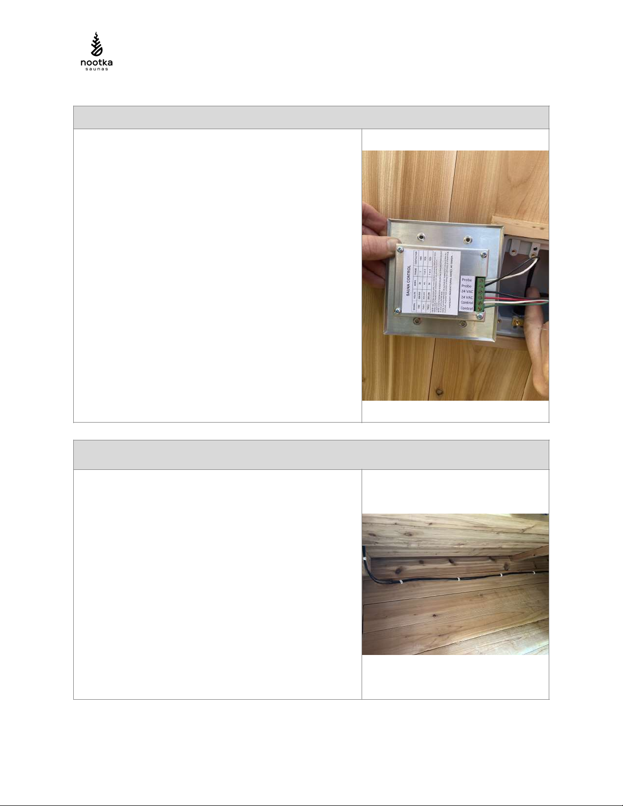
2. Mount the Front Display Panel Sensor
First strip, then feed the 18/4 wire through the 2-gang box
on the front wall, between two bench slats and then under
the bench (this will get stapled in step 3). Run the remaining
part of the wire out of the bottom hole from step 1.
Strip and carefully connect both the 18/2 and the 18/4 cables
to the front display panel.
The 18/2 conductors connect to the sensor port (bipolar)
Two of the 18/4 conductors (usually red/black) connect to the
24VAC ports on the controller (bipolar).
The remaining two (usually white/grey) conductors on the
18/4 cable connect to the control port
Secure the nylon cable gland that both the 18/2 and 18/4
wires run through.
Using the 4x 6/32 screws to mount the control screen to the
2-gang box.
Figure)2)-)Rear)of)display)panel
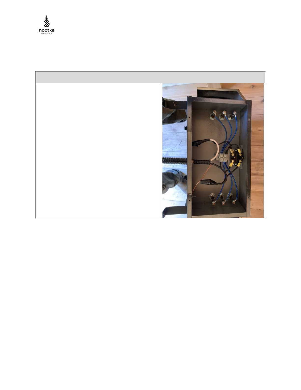
3. Clean Up The 18/4 and 18/2 Wiring
Using the supplied cable staples, discretely run the two
cables under the benches, securing them with cable staples
every 12” or so.
#C

O$K#B9##PQ1+$#AFAAR
Ensure you peel off the plastic film on the temperature sensor
guard prior to affixing to the wall.
Mount the supplied, wooden electrical panel cover to hide
the 2-gang box.
On the rear EXTERIOR of the sauna, secure the cabling to the
circumference of the sauna’s rear wall.
#T
O$K#B9##PQ1+$#AFAAR
PART 2: WIRING THE SAUNA HEATER (CONTINUED)
4. Wire the TECK Cable To the Heater
Remove the heater from the rear wall of the sauna (lift
it up and it will slide off the two hooks it sits on. Flip
the heater upside down and remove the 4x self-
tapping screws from the bottom of the heater.
Use the center rear knockout and mount the supplied
TECK connector. Then feed in one end of the supplied
18/2 teck cable and secure the L1, L2, and GND wires
Use the supplied marrettes for the L1 and L2
connectors and for the GND, use the welded lug.
VERY IMPORTANT: MAKE SURE THE MARRETTE
CONNECTIONS FOR L1 AND L2 ARE VERY SECURE
FOR AND ALSO ENSURE THAT THE WIRES AREN’T
TOUCHING THE WALLS OF THE ENCLOSURE WHEN
YOU CLOSE THE BOX BACK UP.
Flip the heater to be right-side-up and feed the TECK
cable through the hole on the center of the back of the
wall through to the exterior.
#G
O$K#B9##PQ1+$#AFAAR
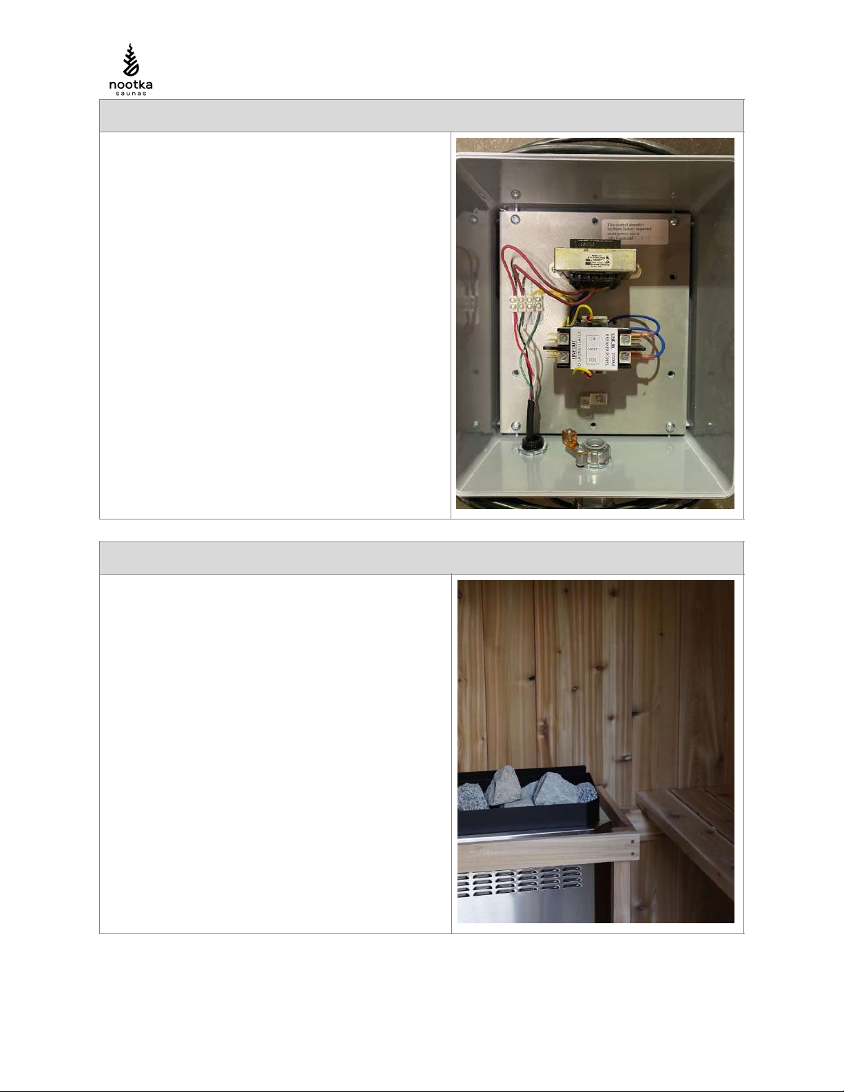
5. Mount the 884 Junction Box To the Rear Wall
Using the supplied 4x 1-1/4” screws, Secure the 884
Junction Box to the rear wall, ensuring it’s in a position
that both the TECK cable and the 18/4 wiring can
reach.
Secure the GND from the “Infeed” side as well as the
“TO HEATER” side to the lug in the junction box.
Secure the L1 and L2 connections on the “TO
HEATER” side of the Contactor.
Feed the 18/4 cable through the nylon cable gland on
the 884 box, strip and secure the conductors in the
same order that you followed in STEP 2.
Secure the TECK cable and the 18/4 cable to the wall
with the supplied bracket and cable staples,
respectively.
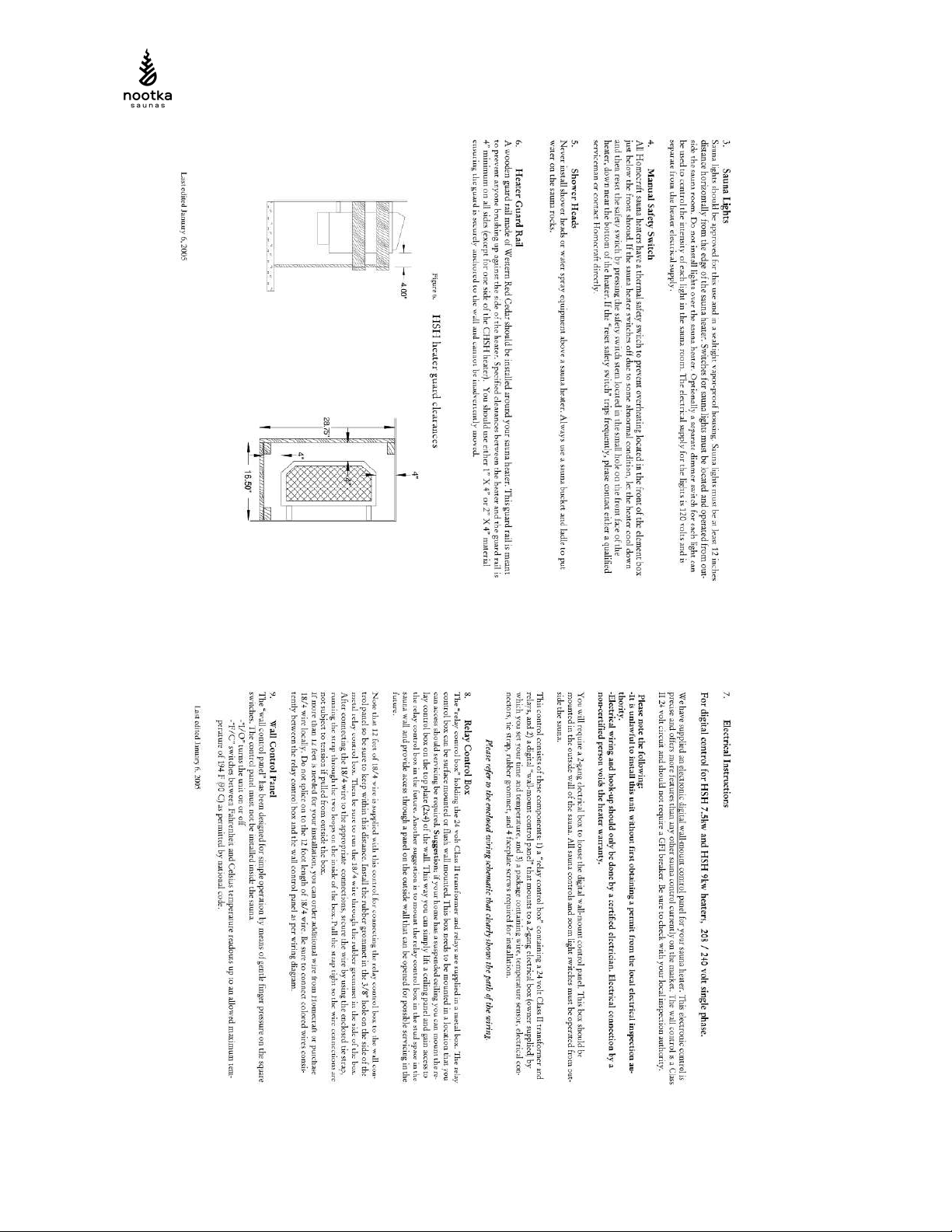
6. Mount the Heater Guard and Add the Rocks
The wiring is now complete. Place the rocks gently
onto the heater, ensuring there is some room for air to
flow (packing the rocks too tightly can cause the heater
to overheat).
Finally, mount the Heater guard to the rear wall with
the supplied 2.5” wood screws
#U

O$K#B9##PQ1+$#AFAAR
PART 3: TROUBLESHOOTING
TROUBLESHOOTING(CHECKLIST(
L'.13"$0/..7+,#210$#5.+$#36#)#%$'78$5#$"$%&'(%()+#)+5#(+#)%%.'5)+%$#*(&/#&/$#
2)+1-)%&1'$'>0#'$%.22$+5)7.+09#
Initial Checks:!
1. Is the incoming power actually 240VAC? We’ve seen issues before where only ~190V is coming in (one of
the legs is compromised) and this ends up giving enough power to sometimes show life on the front control
power but not enough power to pull in the contractor).
2. Is the power leaving the transformer in the rear wall junction box 24VAC (use a multimeter to check)?
3. Check that all the 18AWG wires in the rear wall terminal block are secured. Also check that the 18AWG
wires in the front control panel are connected and secure.
Troubleshooting Checklist:
1. Do you see numbers/display on the front wall!display?
YES: Move to 2.!
NO: !24VAC isn’t getting to the controller. Check the incoming power and make sure the 24VAC labelled 18AWG
wires are properly seated/connected into the display and into the!terminal blocks on the back wall junction box. Also,
ensure that the low voltage wiring hasn’t been punctured or damaged during the sauna assembly. For example, a
screw through the 18/4 wire will short circuit the output side of the transformer.
2. When you hit ON, does the display show a temperature read out (the current ambient temperature)?!
YES:!Move on to 3.!
NO: It reads OPEN.!The temperature sensor wires are disconnected (either where they go into the front wall display
panel, or near the ceiling above the heater where they are soldered to the thermistor that’s mounted to the wall.
Check both for good connection.!
3. When you hit ON/OFF do you hear a dull thud from the back wall!junction box?
YES:!That’s good, it’s the contactor being pulled in, move to Step 4.!
NO:!The contactor isn’t getting pulled in. It’s very unlikely to have a faulty contactor, more likely that the “Control
wires” that go back to the contactor from the display control panel are not connected well or are damaged. With a
multimeter, check the control wires at various points all the way back to the contactor to see if you’re getting 24VAC.!
4. Is there any heat being produced in the sauna after a minute?!
YES:!You’re good to go then
NO:!
a) the thermal temperature limit switch at the base of the heater might be tripped. Look at the black base of
the heater and you’ll see a hole with an arrow that says RESET. Press that in with a screwdriver or similar thin object.
You’ll hear it click if it reset.!
b)!The heater wiring might be loose or not connected properly. Dismount the the heater guard, remove the
rocks and flip over the heater to inspect the wiring and ensure a good connection between L1, L2 and GND.!
#BF

O$K#B9##PQ1+$#AFAAR
PART 4: SAUNA HEATER MANUAL
(
(
#BB
O$K#B9##PQ1+$#AFAAR
(
(
#BA

O$K#B9##PQ1+$#AFAAR
(
#BH
Table of contents
Popular Heater manuals by other brands


DeLonghi
DeLonghi Radia R 030715 instructions

Newa Pond
Newa Pond NWPH 200 instructions

Consort
Consort CN2LSTRX manual

Sentiotec
Sentiotec IR-WP-175 Instructions for assembly and use

Clarke
Clarke DEVIL 370SPC Operating & maintenance instructions

Russell Hobbs
Russell Hobbs RHMFHO1 Installation manual and operating instructions

Sunpak
Sunpak S34-TSH Supplementary instructions

BE
BE HL062B user manual

Empire Products
Empire Products RH-25-6 Installation instructions and owner's manual

Orbegozo
Orbegozo CV 2300 instruction manual

Detroit Radiant Products
Detroit Radiant Products DGS Series installation manual

Macro Design
Macro Design WEV manual