BGU FSW 5.5 H Evolution Product information sheet
ORIGINAL USER’S MANUAL
Carefully read these instructions before starting
to skid with your log winch!
Südharzer Maschinenbau GmbH
Helmestraße 94 ∙ 99734 Nordhausen/Harz
Zentrale: 03631/6297-0 ∙ -111
Internet: www.bgu-maschinen.de
e-mail: [email protected]
- Setup & instal
lation
- Use
- Maintenance
- Accessories
Logging winch
FSW 5.5 H Evolution
(hydraulic version)

2
CONTENTS
1. GENERAL INFORMATION 4
1.1 About this manual 4
1.2 Delivery and transport claims 4
2. SAFETY PICTOGRAMS AND WARNING LABELS 6
3. SAFETY 7
3.1 Mandatory application field 8
4. PTO-POWERED OPERATION 10
5. OPERATION 10
5.1 Tractor requirements 10
5.2. Attaching the winch to your tractor 10
5.3 Positioning the drawbar to the PTO shaft 11
5.4 Wire rope installation 11
5.4.1 Unwinding the wire rope 12
5.4.2 Checking the wire rope quality 12
5.4.3 Winding up the wire rope 12
5.4.3 Adjusting the wire extension force 13
5.5 Skidding 13
5.6 Settings 13
5.6.1 Clutch 14
5.6.2 Prebrake regulation 14
5.6.3 Brake 14
5.6.4 Stretching of the drive chains 15
5.7 Lubrication 15
5.8 Checking the hydraulic oil level 16
5.9 Troubleshooting 17
6. REPAIRS And 18
MAINTENANCE 18
6.1 Periodic maintenance 18
6.2 Effects of overload and misuse 19
6.3 About hydraulic oil 20
6.4 Consumables 20
7. DISPOSING OF AN OBSOLETE WINCH 21
8. HydrauliC DIAGRAM 22
9. TechniCAL SPECIFICATIONS 23
10. WIRING DIAGRAM 24
11. OTHER AREAS OF POSSIBLE DANGERS 25
11.1 Mechanical dangers 25
11.2 Electric danger 25
12. LEGAL WARRANTY 26
13. EXTENDED WARRANTY 26

3
14. FSW 5.5 H, ExploDED VIEW 27
15. FSW 5.5 H, Spare PART LIST 28
16. OPERATION TIPS 30
FOR NEW WINCHES 30
17. EC STATEMENT OF COMPLIANCE 31

4
Dear customer,
Thank you very much for your trust and preference in choosing our equip-
ment and joining the number of our best customers in the world. We are
confident that our equipment will be up to all your expectations and assu-
re you a long lasting quality and performance.
Our timber winches are available in different versions of different pull force.
FSW 5.5 pull force 5,5 tons Hydraulic operation system
All versions are designed and conceived for farming and logging applications.
Any other use shall be considered non-compliant application.The manufacturer
accepts no responsibility for damages caused by non-compliant application. In
this case the operation of the machine is completely at user’s risk.
1.1 About this manual
Please take time to read this manual and learn to how operate and
maintain the loader safely. For your easier reading this manual is laid
out in several sections. The sections are progressively numbered 1
through 18 and listed on the “content” page. The information, pic-
tures and technical data in this document reflect current or planned
product features, functions, and characteristics as of the publication
date. Because of on-going product improvements and feature additi-
ons, information in this document is subject to change without notice.
If you are experiencing a problem or functional trouble on your ma-
chine, please read the “trouble-shooting” section to identify possible
causes and remedies. When you have checked all the possible causes
listed and you are still experiencing the problem, ask your Authorized
Service Centre for help. When you order parts maintenance or repair
services, your Authorized Service Centre, your dealer or eventually
the manufacturer need your machine serial number and engine serial
number. These are the numbers that you have recorded on the pro-
duct identification label of the manufacturer on the machine.
1.2 Delivery and transport claims
Upon delivery of the machine please check for visual machine dama-
ges such as damaged packing or scratched buckled parts. If so, make
a remark on all copies of the delivery bill (including the one for your
own use) and have the driver sign for acceptance before unloading.
1. GENERAL INFORMATION

5
Have the truck driver accept your claim by hand signing it.
Should your shipper or the truck driver refuse to accept your claim
and countersign the delivery bill, fully reject delivery and make sure
to inform us (the manufacturer) immediately. No claims shall be taken
into account by the shipper or by the insurance company, if a reserva-
tion note is not made on the delivery bill.
All transport damages must be notified within latest 2 days from de-
livery. Therefore delivery must be collected and inspected within this
term. Later claims shall be disregarded. In case of assumed but not
visually clear transport damages make sure to mark the following sen-
tence on the delivery bill : „Reserved delivery due to assumed trans-
portation damages“.Insurance and shipping companies act with extre-
me caution in case of transport damages and sometimes refuse to ac-
cept responsibility. Ple-ase make sure to provide clear and exhaustive
evidence (photos) of the claimed damages.
Thank you in advance for your help and understanding in this matter.
6
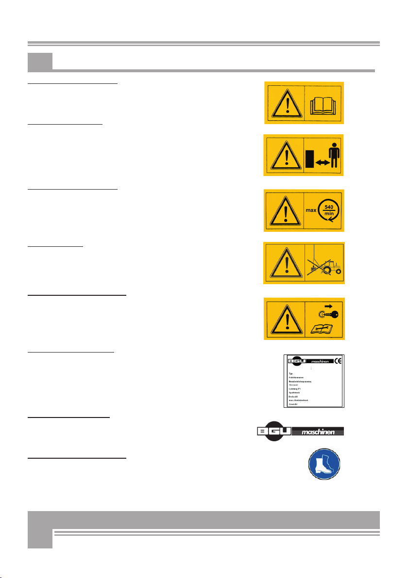
2. SAFETY PICTOGRAMS AND WARNING LABELS
1 . Machine safety label
„Read, understand, and follow all instructions in this manual and
on the machine before starting!
2. Safety pictogram
„Do not infringe the dangerous zone“
Avoid standing in the dangerous zone between the tractor and
the log loader.
3. Machine safety label
" max 540 min"
This label shows the max admissible number of PTO shaft revo-
lutions the direction of rotation of the driveline.
4. Danger sing
„No hoisting!“
5. Machine operation sign
“Disconnect the winch, read and comply with manufacturer’s
maintenance instructions.” "
6. Identification label
„Product identification“
This label shows the company details of the manufacturer and
the main machine technical data.
7. Identification label
„BGU-Maschinen” manufacturer’s logo
8. Operator’s safety label
„Wear steel-toe safety shoes”

7
Strictly perform installation, set-up, maintenance, cleaning
and transportation of the winch with the power switched off
and all moving parts motionless against accidental operation.
The user shall strictly comply with these operation, set-up, mainte-
nance, repair and trouble-shooting instructions in order to assure safe
operation and no damages to the equipment. Moreover, we recom-
mend let the machine be run only and strictly by trained and skilled
staff who must be familiar with the applicable occupational safety and
health administration rules as well as applicable transportation rules.
Incorrect use of the winch can cause serious injury or death.
No person under school leaving age should operate a logging winch.
Those who have reached school leaving age but are below the age of
18 may operate a winch if supervised by a competent person of 18
years or over.
The machine shall be installed and kept in a suitable location selected
by the customer for safest operation.
The working area around the machine must be kept as clear as pos-
sible from surrounding obstacles and slippery foundation floors should
be duly treated (do not use saw dust or wood ash for this purpose).
Make sure that the equipment stands on a safe stable foundation.
• Due and proper illumination of the working site must be provided at
all times.
• Set up the winch on a firm surface and ensure that a wide but
confined area is available around it assuring maximum working free-
dom.
• Mind all operation sings and warning labels on the winch and comply
with the instruction given herein.
• Operators must wear steel toe safety shoes, working protective gloves,
protective helmet and snug-fitting, tear-resistant work cloths.
• It very dangerous and strictly prohibited to sit/stand on the winch
while transporting it.
• Never leave the winch unattended while at work.
• Before switching power on and putting the winch to work make sure
that there are no bystanders in the dangerous area and that you
have good and clear visibility on the work area.
• Provide due and correct mounting of the winch.
• Make sure to comply with driving speed requirements for the
specific road conditions. Use caution when changing direction or tur
ning while skidding uphill, downhill or across slopes.
3. SAFETY

8
• Do not stand in the dangerous area. Assure that nobody stands
inbetween winch and tractor, unless the tractor is safely braked and
blocks have been put underneath the wheels to avoid accidental
moving.
• Do not remove nor start handling timber before the winch has come
to a complete stop.
• Periodically check that all screws and fixations are tightly in place.
• Before putting the winch to work perform a visual checkup of the
overall conditions and let a skilled technicial overhaul and service
your winch at least once a year.
• It is strictly prohibited to use the winch for any other application
than mentioned in this manual. CAUTION: do not use the winch for
hoisting applications! (Figure 5)
• Make sure that power is fully disconnected from the winch and that
the tractor has been switched off before performing any repair or
work on the winch.
• Never operate the winch without its safeties and protections duly in place.
• Strictly use wire rope of adequate crush resistance, strength and
quality. Provide for immediate wore rope replacement, if any fault
or anomaly is detected.
• Be sure that your wire rope length provides for a free gap to the up
per drum profile of least 1.5 the rope diameter when fully spooled.
In other words, when the rope is fully spooled there should be
space left on the drum for at least two more coils.
• Make sure that your helpers do not put any extra load on the winch
without prior informing the tractor driver.
• Strictly operate the winch from a safe place, at safety distance from
the load, the rope and such other dangers as unfelled trees. The
driver seat accounts as a safe place only if a safety screen is provi
ded to separate the winch from the tractor in such a way that it may
not be removed or bypassed.
The work site and the area around the logging winch must be kept
free from hinders and obstacles. Make sure that all access ways are
properly maintained so that timber can be safely skid, loaded and
shipped.
3.1 Mandatory application field
Our logging winches are designed and conceived for farming and tim-
ber skidding applications. Any other use shall be considered non-com-
pliant application. The manufacturer accepts no responsibility for da-
mages caused by non-compliant application. In this case the operati-
on of the machine is completely at user’s risk.
The user shall strictly comply with these operation , set-up, mainte-
nance, repair and trouble-shooting instructions in order to assure safe
operation and no damages to the equipment.

9
• CAUTION: it is very dangerous to stand in front of a tree to be felled and winched away. (Figure 1)
Fig. 1 Fig. 2
• Winching with a pulley originates a three-sides dangerous area where none is allowed to stand
during winching operations. (Figure 2)
• Never exceed the max admissible pull angle of 30° (Figure 3).
• CAUTION: tip-over risk (Figure 4) when winching on rough terrain or exceeding the maximum
admissible pull angle.
Fig. 3 Fig. 4 Fig. 5
Keep away from the dangerous area!
• You and your helper must establish clear and precise hand signals and review them so everyone
clearly understands.
Pull Stop Let the rope
loose
• If your winch is equipped with lower snatch block, use it also for pulling operations.
• The operator should monitor the load throughout the entire pulling operation. Although winches are
one-man equipment, you should never work alone and a second person should be ready to help in
the event of lack of full visibility.
• Attach your winch to any tractor equipped with road transport tires to avoid infringement of road
travel profi les. If this is not available, provide your towing vehicle with protection chains. Chains are
mandatory on all types of tire for travel on icy or snowy foundations.
• Before disconnecting the winch from the tractor, park on a safe and fl at surface. Drive the winch
down on the special stabiliser foot and hang the driveshaft on the special mount provided on board
of the winch.
• Pinched-hands and injuries danger in the three-point hitching area!
Read this basic guide carefully, familiarize yourself with the operation of your
winch before having to maintain it and be constantly safety oriented!
Fig. 1 Fig. 2
Fig. 1 Fig. 2
Fig. 1 Fig. 2
Fig. 1 Fig. 2
Fig. 1 Fig. 2
Fig. 1 Fig. 2
Fig. 1 Fig. 2
Fig. 1 Fig. 2
Fig. 1 Fig. 2
Fig. 1 Fig. 2
Fig. 1 Fig. 2
Fig. 1 Fig. 2
Fig. 1 Fig. 2
Fig. 1 Fig. 2
Fig. 1 Fig. 2
Fig. 1 Fig. 2
Fig. 1 Fig. 2
Fig. 1 Fig. 2
Fig. 1 Fig. 2
Fig. 1 Fig. 2
Fig. 1 Fig. 2
Fig. 1 Fig. 2
Fig. 1 Fig. 2
Fig. 1 Fig. 2
Fig. 1 Fig. 2
Fig. 1 Fig. 2
Fig. 1 Fig. 2
Fig. 3 Fig. 4 Fig. 5
M
M
a
a
M
a
M
x
x
3
3
0
0
°
M
M
M
M
a
a
x
x
3
3
0
0
°
Pull Stop Let the rope
loose
Pull Stop Let the rope
loose
loose
loose
loose

10
4. PTO-POWERED OPERATION
Use only and strictly CE approved drivelines duly connected and secured in compliance with the
manufacturer’s instructions.
• Never use a PTO driveline without safety shield or with a damaged guard.
• Make sure that the shield is of the correct size and length for the drive shaft and is duly mounted on it.
• Use safety chains to secure the shield agaist dangerous rotation and distortion.
• Before operating the PTO driveshaft make sure the rpm-number and direction comply with the one
shown by the arrow-sign on the winch. Take all due measures to avoid unauthorized thirds standing
the the dangerous area of the winch!
Never run the PTO shaft when the tractor motor is switched off! After dismouting the PTO
shaft use the special holder on the winch to safely store it away.
5. OPERATION
This logging winch is designed for skidding applications only. The winch comprises a welded frame, a
main shaft, a chain wheel clutch, a drum with wire rope, a brake and a snatch-block.
The wire rope is slipped around the timber, the timber is pulled to the skid and the rope is hung up to
the special grooves in the skid by means of fixation chains. Timber and long tree trunks are so win-
ched to a parking area for loading on trucks and further delivery.
5.1 Tractor requirements
Do not PTO operate winch at any faster speeds than max. 540 RPM.
To mount your winch to the tractor use three-point hitch CAT I and Cat II only.
5.2. Attaching the winch to your tractor
Make sure that nobody stand in the dangerous area while connecting the winch
to your tractor
Logging winches can be mounted on any tractor equipped with 3-point hitch of category I or II.
With a special arrangement it is also possible to mount the winch to a tractor with automatic hitch
mechanism on the lower hitch points.
Make sure to strictly use approved IID types and that proper shielding with chain fixation is available.
Make sure to perform accurate connection of your PTO driveline both on winch and power input side.

11
5.3 Positioning the drawbar to the PTO shaft
The length and height of a tractor drawbar may need to be adjusted to match the implement to the
manufacturer’s specifi cations. It is important to make these adjustments to ensure that the PTO drive-
line does not compress or separate during operation.
To make this adjustment:
• Mount the winch to the tractor!
• Pull the two halves of your shaft apart and respectively mount them to the tractor and to the winch
and perform a crosscheck as shown below (Fig. 6)
• For increased safety make sure that a minimum wrapping of 200mm (b) occurs when pulling the
hitch bar all the way up and down. With the shaft parallel to the ground also make sure that the shaft
doesn’t hit the stand (wrapping (a) should be still at least 20mm).
• For shortening of the PTO shaft, fi rst cut the telescope off and then the external one by the same
length.
• Grind both shaft ends, clear chips and dust away and oil all slinding contact areas before fi nal
assembly.
Fig.6
5.4 Wire rope installation
DO! DON‘T!
Remove the small protection grid and then take the cap off. Now turn the drum to the right position
for releasing and removing the drum screw.
Insert the wire rope through the inlet fairlead (on top) and feed it to the drum by means of the upper
block. (Fig. 9, Pos. 8).
In order to transfer torque from the tractor to the winch you must use a driveline with torque
overload clutch coupler. Mount the winch to the tractor and then secure the stabilisers underne-
ath the lower hitch points. Finally incline the winch by approximately 20° using the upper hitch
bar.
b
a

12
Fit the rope into the special groove and tighten the screw (Pos. 9). Now start spooling as described
under pulling procedures.
In order to avoid possible rope damages keep winding up for a while after complete spooling of the
entire rope length, as described under section “Spooling of the wire rope”.
5.4.1 Unwinding the wire rope
After you have correctly installed the winch, you can start unwinding the rope. However, it is impor-
tant that you first switch the rear lights of your tractor on, so that the right voltage is available in
your power connection.
• Disengage the brake by pressing the white push-button (2) [Fig. 7].
• Press the black push-button (1) [Fig. 7] to engage the brake and start unwinding the rope. If no
unwinding is possible, you may have a pressure problem in your system (not enough operating pres-
sure). In this case, start the driveline to activate the hydraulic pump.
• Press the white button again and start pulling the rope. If the remaining rope is not duly spooled,
keep unwinding all of it up to the last 3-4 winds and then rewind to the required length.
• If your timber gets stuck against an obstacle (tree stumps or roots) during skidding, you may have
to stop winching if the obstacle cannot be bypassed. In this case, a large amount of residual force
may bild up in your wire rope causing jerky unwinding. If this happens, repeatedly press (2-3 times)
the white push-button (1) at very short intervals in order to release the tension from the wire rope.
5.4.2 Checking the wire rope quality
• Stricly use brand new ropes.
• Make sure to use ropes of approved quality, suitable strength and compliant to the specifications
identification label.
• Do not use longer ropes than instructed in the technical specifications of this manual.
5.4.3 Winding up the wire rope
Completely spool the rope making sure to wind it tightly and evenly onto the drum and avoiding both
overwinding and underwinding.
Correct winding is accomplished by:
• Simply pulling of a load
• Firmly attaching one end of the cable to a stable anchor-point suitable to withstand the pull force
while the rope starts spooling onto the drum pulling tractor and winch towards the anchored rope end.
It may be convenient to carry out this operation either on a slight gradient with the idled tractor facing
uphill or alternatively with braked tractor.
Wind the rope tightly and evenly onto the drum. Before putting your winch to
work spool the rope completely off and then rewind it again! Check the rope over
for any signs of damage, flattening, broken wires, wear and corrosion.

13
5.4.3 Adjusting the wire extension force
The wire extension force must set accurately, so that the drum stops at once when pulling no longer
occurs. This will avoid dangerous drooping and sagging of the wire rope.
To adjust the wire extension form:
• release the fi xation nut
• release or tighten the screw acting on the brake band through the leaf spring
• tighten or release the screw to either increase or reduce the extension force
• tighten the fi xation nut again
5.5 Skidding
Set the hydraulic cylinder of the tractor three-point hitch in its lowest position. Firmly settle the winch
down on ground, engage the tractor manual brake and then start skidding your load. Press the black
push-button on the control panel to start spooling the rope on the drum. The rope must stop winding
up as you release pressure on the black push-button.
For safety reasons, windind of the rope is strictly possible by holding a consistent fi nger pressure on
the black push-button.
Do not raise the winch during skidding operations! (DANGER: you may damage your
driveline)
The nominal pull force is the maximum pull obtained with the fi rst rope windings on the drum. This is
the fi gure stated in the technical data and the manufacturer‘s identifi cation plate on the machine. The
pull force decreases as the rope winds up on the drum. The pulling speed is inversely proportional to
the pull force and reaches the peak speed as the rope is fully spooled onto the drum. With the rope
fully spooled on the drum, the pull force amounts 50-60% of the nominal fi gure.
5.6 Settings
3 Brake disengaged for a long time
2 Brake disengaged for a short time
1 Pull
Fig. 7

14
5.6.1 Clutch
Before attempting any intervention, make sure to first switch the tractor engine off and
remove the ignition key!
Proper clutch settings will ensure optimum pull force. The clutch is set by the manufacturer during
final testing of the product before shipment. However, possible wear of the lining may require some
extent of adjustment as the time passes. Clutch adjustment should be performed every time when
your winch no longer reaches the required pull force.
To perform clutch adjustment:
• loosen the nut shown in Pos. 1
• slightly tighten the nut in Pos. 2
• on engaging of the clutch, switch the motor on and start the driveline
• if the rope winds up although you are not pressing the black push-button (1), then you probably
tightened the nut (Pos. 7) excessively and there is no more clearance between the drum and the
clutch. In this case, release the nut and repeat the setting procedure till the rope stops winding
unless the black push-button is pressed.
5.6.2 Prebrake regulation
To facilitate winding of the wire rope, perform prebrake regulation with the screw (10) and respective
wingnut (11) (Fig. 8). Exact prebrake regulation will also prevent the rope from unwinding excessively
fast or accidentally slipping off the drum. Extreme fast unwinding and abrupt brake disengagement
may cause severe damages to the wire rope. Exact prebrake regulation occurs when the rope can be
effortless spooled off the drum. The prebrake arrangement must be disengaged for uphill winching
operations in order to ensure easier pulling of the rope. A pre-braking function is also performed
by the inlet fairlead Pos. 12, (Fig. 8) where the rope is inserted. Exact prebrake regulation will also
prevent the rope from unwinding excessively fast or accidentally slipping off the drum. Extreme fast
unwinding and abrupt brake disengagement may cause severe damages to the wire rope.
Exact prebrake regulation occurs when the rope can be effortless spooled off the drum.
The prebrake arrangement must be disengaged for uphill winching operations in order to ensure
easier pulling of the rope.
5.6.3 Brake
On completed pulling, the differential brake automatically takes the load over (the drum should not be
allowed to unspool and the rope must remain stretched).
The brake is preset by the manufacturer before shipment. However, it is possible that slight wear of
the brake band lining occurs requesting some additional adjustment. Brake readjustment must be
performed every time when the load cannot efficiently hold back any longer.
To perform readjustment:
• tighten the nut (Pos. 3) Fig.8 used to lock the spring
• adjust nuts (3) and (4) to obtain a 7 mm gap between nut (1) and (3) on the threaded spindle
• tighten nut (4) to complete the procedure

15
Fig. 8 Fig. 9
4
10
11
13
12
6. 7
8
9
15
3
14
1
2
4
5
6
5
3
8
9
10
11
7
2
1
5.6.4 Stretching of the drive chains
After the first operation hours you possibly experience some extent of release of the drive chain that
will then need to be restretched. Therefore you need to check the chain after the first 10 operation
hours for the first time and then regularly every 60 operation hours.
To accomplish stretching of the chain (refer to figure 9) and:
• remove the safety guard (1) on the chain, remove screw (2) and loosen (without removing) the 4 screws (3)
• loosen nut (6) of the adjustment screw (4) and then screw the adjustment screw tight on nut (5)
• keep tightening nut (5) until chain (7) is completely stretched
• adjust the chain so that you can still provoke some extent of deflection by applying one finger tip
pressure in the middle.
• then make the PTO shaft (8) turn and check for troublefree and effortless turning.
• check the pump chain (9) to make sure that it is excessively stretched and if required adjust it by
loosening the screw (10) and tightening the nut (11).
5.7 Lubrication
Make sure that the motor is switched off and the ignition key has been removed
before performing any maintenance/repair work on the machine.
Your logging winch is equipped with 4 nipples for the lubrication of the upper pulley and lower
snatchblocks as well as the rope fairlead. Additional lubrication is then required on nipple (13) of the
prebraking arrangement (12) (Fig.8).
Perform lubrication every 15-20 operation hours.
improper lubrication may cause dangerous contamination of the clutch sliding parts for
which the manufacturer will accept no liability!
3
16
Lubricate the drive chain every 40 operation hours.
Use grease suitable for high temperature (it should not melt as common low-price lithium grease) in order
to prevent grease contamination of the sliding clutch surfaces. Accurately clean the chain before greasing.
Make sure to avoid contamination of the clutch lining with grease as this may
lead to a significat loss of the pull force and to early wear of the clutch plates that
will then need to be replaced!
The winch is equipped with self-lubricating bearings that require no further lubrication or maintenance.
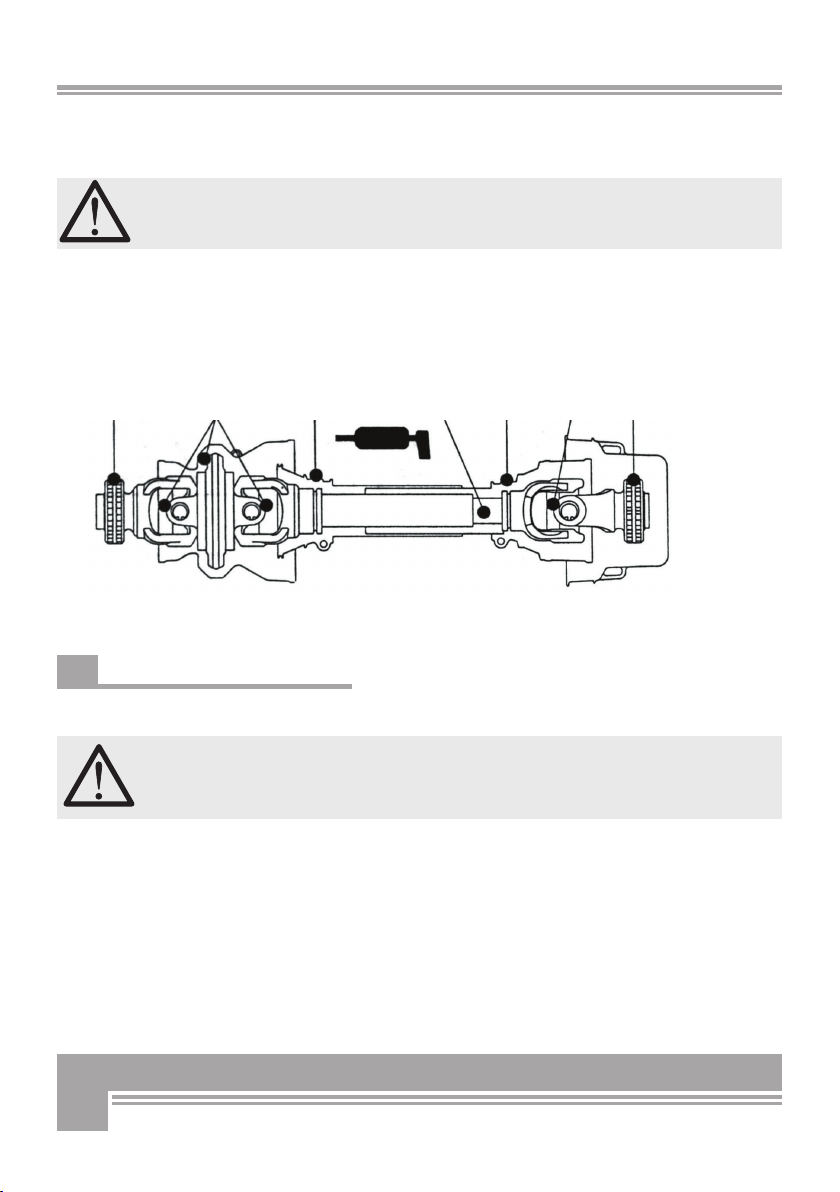
Provide PTO shaft lubrication in accordance with the instructions of the manufacturer (Fig. 10).
5.8 Checking the hydraulic oil level
Make sure to check the oil temperature every once in while during operation. Should the
temperature exceed 70°C, stop working, disconnect power, search and
fix the cause for overheating before continuing to work. DANGER: ex-
cess heat over a prolonged period of time may lead to even permanent
damages of the hydraulic circuit
40 h 8 h 40 h 16 h 40 h 8 h 40 h

17
Trouble description Possible origins Remedies
No winch response when
pressing the buttons or
engaging the plug of the
control panel or the radio
control
• The winch drives are damaged
• No power available
• Control valve out of service
• Check the winch drives (the driveline
must be duly connected for the pump to
operate) and ensure that there is enough
oil in the tank
• Check the power connections (plug on
the tractor, side lights ON)
• Check the batteries of your radio control
and make sure they‘re not rusty. If nee-
ded clean them.
• If power is missing, remove cause of
the blackout
• if the control valve is temporarily out of
use, try concurrent activation of the but-
tons on the control panel und the pressu-
re pads located in the middle of the ma-
gnets front side. If the problem is just a
temporary jamming, this will release the
valve.
Winch is not pulling
enough
• Too much rope on the drum
• Oil on clutch discs due to bad
lubrication of the drivechain
• Clutch lining worn out
• Winch drives are damaged
• Insufficient oil pressure
• Clean or change the clutch lining
• Replace the clutch discs
• Replace damaged parts
Oil pressure lower than
145 bar
• Not enough oil in the tank • Check the oil level and touch-up if nee-
ded. Seal all leaking points.
Oil pressure insufficient • The pump is damages
• Wrong setting of the pressure
switch or safety valve
• Ask for service
• Ask for service
The operating pressure
drops very rapidly although
the winch is not in use
• Damaged non-return valve,
pressure relief valve, control
valve or pressure accumulator
• Ask for service
Brake is not holding • Wrong brake regulation
• Grease on the brake band lining
• Damaged brake mechanismus
• Worn-out brake band (collar)
• Adjust brake force
• Clean the brake lining and the brake
surface on the drum
• Replace damaged parts
• Replace brake collar
5.9 Troubleshooting

18
Trouble description Possible origins Remedies
Rope is hardly
spooling off
• Wrong setting of the pull force
• Damaged rope
• Damaged brake band (collar)
• Seilauszugskraft nachstellen
• Seil wechseln
• Bremsband wechseln
The rope reels in even
if the clutch is released
• Wrong setting of the clutch
cylinder hub
• Drum is damaged
• Clutch discs are damaged
• Driving chains excessively
stretched
• Adjust cylinder hub
• Replace drum
• Change clutch
6. REPAIRS AND
MAINTENANCE
Make sure that the machine is fully disconnected and
all moving parts are secured before performing any
maintenance/repair work on the machine.
6.1 Periodic maintenance
Before starting to work with your winch, make sure to perform the fol-
lowing visual inspections:
• Make sure that all screws and nut are tight
• Check for mechanical damages to the winch chassis
• Make sure that all locking pins and rings are in place
• Check for PTO shaft correct installation and connection and make
sure that safety shield and chains are duly in place.
• Check the lower hitch points of the tractor and make sure they are
firmly secured (no cross, horizontal movement).
• Check for clutch proper setting, check the brake and the rope pull
out force
• Make sure to fix any anomaly or problem before starting to work.
Perform the following maintenance works when needed and carry out
periodic checkup:
• Hydraulic oil level control: if leaks are detected check the tightness
of the remaining system (hoses and fittings) before continuing
• Lubricate all moving parts as needed

19
What to do? When to do? How to do?
• Spool the rope out until 3-4 winds
are left on the drum and strongly
pull with load on
• Check the rope fixation
• Only for new winches
• Always when the rope is loose
visually
• Check the chain tension
• Replace the clutch discs
every 48 operation hours if required
or after 3000 operation hours
by customer service
• Replace the brake collar Every time when adjsting the brake
force is no longer possible and
latest after 3000 operation hours
by customer service
• Lubricate the drive chain all 48 operation hours Lithium grease
• Lubricate the bearings of the up-
per and lower snatchblocks as well
as all other sliding parts
at lease once a month Lithium grease
• Clean casings inside every 100 operation hours or more
frequently in case of hard working
conditions
Loosen all screws and
remove cover making
sure to avoide remo-
ving of the nuts
The winch functionality and safety are tested by the manufacturer. For any repair
or intervention on the winch make sure to strictly use original spares only. Use
of non-original parts and spares will void your warranty just as well as wrong re-
pairs or changes.
6.2 Effects of overload and misuse
• burning of the clutch or brake collar lining
• damaged brake mechanism
• tearing of the chain
• broken rope reel or damaged reel bearing
• damaged power drive/PTO shaft housing
• damaged power drive, PTO shaft or chain wheels
• strain of winch frame parts
• overstrained, cracked, broken lines, rope or Choker-chain
• deformed drum axle.

20
6.3 About hydraulic oil
Periodically check the oil level inside the hydraulic oil tank.
When doing so, accurately avoid contaminating the tank with
dirt, wood chips, sow dust etc... Make sure that the winch
never runs without oil or with a low oil level. When this hap-
pens, air is likely to reach inside the hydraulic loop. Failure to
maintain due oil level may cause poor running and irregular
operation (very rough, jerky motions) as well as major pump
damages. Please schedule your first oil change after approxi-
mately 200 operation hours, the second one after each 600
operation hours and the following one after every 1000 opera-
tion hours or at least once a year.
Recommended hydraulic oils are:
Mobil DTE 16, Shell Tellus T 46, Castrol Hyspin AVH 46
Make sure to check the oil temperature every once in while
during operation. Should the temperature exceed 70°C, stop
working, disconnect power, search and fix the cause for over-
heating before continuing to work. DANGER: excess heat over
a prolonged period of time may lead to even permanent dama-
ges of the hydraulic circuit.
When changing the oil, never let used oil drop down on the
ground, rather collect whole of it in a sealed container for due
disposal. Oil disposal containers should be of at least 7 l ca-
pacity. If you are using smaller containers, make sure to drain
the tank in more than one round to avoid spilling old oil out on
the ground.
Used oil is very polluting and should be disposed in accordance
with local provisions!
6.4 Consumables
• Brake collar (Code No. 901532)
• Sprocket assembly m. clutch (Code No. 901531)
6.5 Accessories
On the machine is a hydraulic rope ejector with inlet brake equipped
in standard.
Table of contents
Other BGU Winch manuals


Popular Winch manuals by other brands


Comeup
Comeup DV-6s manual

Ronstan
Ronstan Andersen Compact Motor 52ST product manual

Speedway
Speedway 7253 manual

DK2
DK2 EW8020 Assembly & operating instructions

Rugged Ridge
Rugged Ridge Extreme Heavy Duty 2.0 owner's manual

Columbus McKinnon
Columbus McKinnon YaleMtrac Operating and maintenance instructions